Zell AC2000 User manual

ZELL AC2000 Automobile Air-Con Service
Solution with Printer & Heat Belt
Operation Manual

1
Contents
1 About this operation manual . . . . . . . . . . . . . . . . . . . . . . . . . . . . . . . . . . . . . . . . . .2
1.1 Zell hot-line. . . . . . . . . . . . . . . . . . . . . . . . . . . . . . . . . . . . . . . . . . . . . . . . . . . . . . . 2
1.2 Explanation of symbols in this operation manual . . . . . . . . . . . . . . . . . . . . . . . . . .3
2 Scope of delivery . . . . . . . . . . . . . . . . . . . . . . . . . . . . . . . . . . . . . . . . . . . . . . . . . . . 4
3 Safety. . . . . . . . . . . . . . . . . . . . . . . . . . . . . . . . . . . . . . . . . . . . . . . . . . . . . . . . . . . . . .5
3.1 General safety instructions. . . . . . . . . . . . . . . . . . . . . . . . . . . . . . . . . . . . . . . . . . . . .5
3.2 Warnings on the Air-Con Service Station . . . . . . . . . . . . . . . . . . . . . . . . . . . . . . . . . . 6
3.3 Safety devices. . . . . . . . . . . . . . . . . . . . . . . . . . . . . . . . . . . . . . . . . . . . . . . . . . . . .. 7
4 Proper use. . . . . . . . . . . . . . . . . . . . . . . . . . . . . . . . . . . . . . . . . . . . . . . . . . . . . . . . . .7
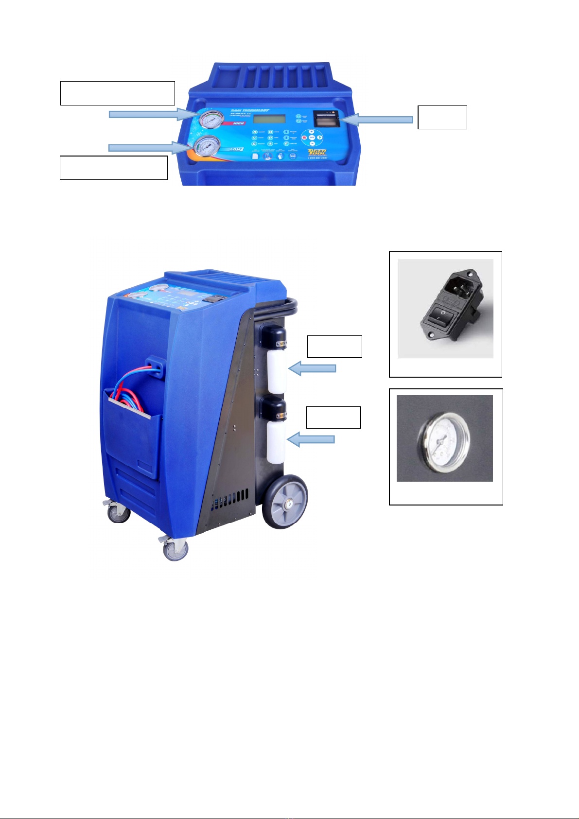
5 Overview of the Air-Con Service Station . . . . . . . . . . . . . . . . . . . . . . . . . . . . . . . . .8
6 First start up . . . . . . . . . . . . . . . . . . . . . . . . . . . . . . . . . . . . . . . . . . . . . . . . . . . . .. . .11
6.1 Setting up and switch up . . . . . . . . . . . . . . . . . . . . . . . . . . . . . . . . . . . . . . . . . . . . . .11
6.2 Putting into the bottles for new oil . . . . . . . . . . . . . . . . . . . . . . . . . . . . . . . . . . . ...12
6.3 Filling up the internal refrigerant container. . . . . . . . . . . . . . . . . . . . . . . . . . . . . . . . ....12
7 Operation . . . . . . . . . . . . . . . . . . . . . . . . . . . . . . . . . . . . . . . . . . . . . . . . . . . . . . . . ....15
7.1 Recovery. . . . . . . . . . . . . . . . . . . . . . . . . . . . . . . . . . . . . . . . . . . . . . . . . . . . . . . . ..15
7.2 Vacuum. . . . . . . . . . . . . . .. . . . . . . . . . . . . . . . . . . . . . . . . . . . . . . . . . . . . . . . . . . ..16
7.3 Purge . . . . . . . . . . . . . . . . . . . . . . . . . . . .. . . . . . . . . . . . . . . . . . . . . . . . . . . . . . ... 17
7.4 Oil injection . . . . . . . . . . . . . . . . . . . . . . . . . . . . . . . . . . . . . . . . . . . . . . . . . . . . . . . 18
7.5 Recharge. . . . . . . . . . . . . . . . . . . . . . . . . . . . . . .. . . . . . . . . . . . . . . . . . . . . . . . . . .19
7.6 Auto . . . . . . . . . . . . . . . . . . . . . . . . . . . . . .. . . . . . . . . . . . . . . . . . . . . . . . . . . . . . 20
7.7 Pressure up. . . . . . . . . . . . . . . . . . . . . . . . . .. . . . . . . . . . . . . . . . . . . . . . . . . . . . . . 21
7.8 Pressure down. . . . . . . . . . . . . . . . . . . . . . . .. . . . . . . . . . . . . . . . . . . . . . . . . . . . .. .21
7.9 Vacuum test . . . . . . . . . . . . . . . . . . . . . . . .. . . . . . . . . . . . . . . . . . . . . . . . . . . . .. . 22
7.10 Record print . . . . . . . . . . . . . . . . . . . . . . . .. . . . . . . . . . . . . . . . . . . . . . . . . . . . .. 24
8. Service tasks . . . . . . . . . . . . . . . . . . . . . . . . . . . . . . . . . . . . . . . . . . . . . . . . . . . . . . . 25
8.1 Inner tank refill . . . . . . . . . . . . . . . . . . . . . . . .. . .. . . . . . . . . . . . . . . . . . . . . . . . . . . . . . . .25
8.2 Language select . . . . . . . . . . . . . . . . . . . . . . . . . . . . . . . . . . . . . . . . . . . . . . . . . . .25
8.3 Zero balance . . . . . . . . . . . . . . . . . . . . . . . . . . . . . .. . . . . . . . . . . . . . . . . . . . . . . . .25
8.4 vacuum pump oil . . . . . . . . . . . … . . . . . . . . .. . . . . . . . . . . . . . . . . . . . . . . . . . . . . .26
8.5 Changing the internal filter . . . . . . . . . . . . . . . . . . . . . . . . . . . . . . . . . . . . . . . . . . . . . 27
8.6 Hose compensation . . . . . . . . . . . . . . . . .. . . . . . . . . . . . . . . . . . . . . . . . . . . . . . . .. .29
8.7 Pressure rise wait . . . . . . . . . . . . . . . . . . . . . . . . . .. . . . . . . . . . . . . . . . . . . . . . . . . .29
8.8 Other service . . . . . . . . . . . . . . . . . . . . . . . . . . . . . . . . . . . . . . . . . . . . . . . . . . . . . . 29
8.9 Cleaning and maintenance . . . . . . . . . . . . . . . . . . . . . . . . . . . . . . . . . . . . . . . . . . . . . . . .29
9. Disposal. . . . . . . . . . . . . . . . . . . . . . . . . . . . . . . . . . . . . . . . . . . . . . . . . . . . . . . . .. . .30
9.1 Disposing of used fluids . . . . . . . . . . . . . . . . . . . . . . . . . . . . . . . . . . . . . . . . . . . . . . .30
9.2 Disposing of packaging material . . . . . . . . . . . . . . . . . . . . . . . . . . . . . . . . . . . . . . . . .30
9.3 Scrapping old unit. . . . . . . . . . . . . . . . . . . . . . . . . . . . . . . . . . . . . . . . . . . . . . . . . . . 30
10 Trouble shooting. . . . . . . . . . . . . . . . . . . . . . . . . . . . . . . . . . . . . . . . . . . . . . . . . . . . 31
11 Technical data . . . . . . . . . . .. . . . . . . . . . . . . . . . . . . . . . . . . . . . . . . . . . . . . . . . . . . 32
12 Spare Part list . . . . . . . . . . . . . . . . . . . . . . . . . . . . . . . . . . . . . . . . . . . . .. . . . . . . .. .32

2
1 About this operation manual
This operation manual describes the Zell Air-Con Service Station
This manual is for those who have the required professional ability of providing
the maintenance service on vehicle air conditioning system.
This manual contains all the instructions necessary for safe and effective
operating of the air Conditioning service Station. Read this operation manual
carefully before putting the device into using for the first time.
Also note the following:
■the operator should comply with the laws about the service of vehicle air-
conditioning by local government.
■the operator should be familiar with basic technical information of vehicle air-
conditioning
■Instructions from the refrigerant manufacturer
■Instructions from the car manufacturer
■Any special instructions on servicing vehicle air conditioning systems which
applied at your company
Keep this operation manual in the tool box of Air-Con Service Station, so that
any information needed is always at your hand.
1.1 Zell hotline
If you need more information about the Air-Con Service Station that is not
concerned in this manual, call Interequip Pty Ltd 18000EQUIP (1800037847)

3
1.2 For illustrating the symbols in this operation manual
Risk of damage to the machine or other material damage
Special information for using the device effectively
2 Scope of delivery
The Air-Con Service Station and its accessories are carefully checked
Format Meaning Example
KEY Symbols used on the device Press
„BOLD” Display messages „LANGUAGE”
■Text
■Text List in any order ■Pressure monitor
■Pressure relief valves
1. Text
2. Text
3. Text
Actions to be carried out in the
order shown 1. Connect the device.
2. Switch on the device.
3. Press the selection button.
Text (1) Part number Use the keypad (7) to enter the
data.
Text (A) Part designations which refer to
the diagrams shown in the
section describing the work
Remove the filter cartridge (E)
on the left side.

4
before shipping.
After delivery, please check all the parts listed below are present
and undamaged.
If any part is missing or damaged, notify the company responsible
for transport immediately
3 Safety
3.1 General safety instructions
AC2000
Air-Con Service Station
Blue hose with coupling for LP connection and red hose with HP connection
Container for air conditioning compressor oil (PAG oil)
Container for used oil
Inner tank refill connector
Power cord
operation manual

5
Read this operation manual carefully before starting up the
Air-Con Service Station for the first time
Please note the following:
■the operator should comply with the laws about the service of vehicle air-
conditioning by the local government.
■the operator should be familiar with technical information of vehicle air-
conditioning
■Information form the refrigerant manufacturer
■Any special instructions on servicing vehicle air conditioning systems
which applied at your company
And also please pay attention to these massages:
→Only use the device for its intended purpose.
→Only use genuine R134a refrigerant .If other refrigerants are mixed in, it can
damage the Air-Con Service Station and the vehicle air condition system.
→Only use the performance of POLYOL ester type refrigerator oil (PAG oil)
used with the R134a.If other oil are mixed in, it can damage the vehicle air
condition system.
→Wear personal safety equipment (goggles and gloves) and avoid touching
refrigerant, as this can cause chilblains to your body.
→Do not inhale refrigerant gas . Although the gas is non-toxic, it displaces the
oxygen you needed.
→Do not make modifications to the Air-Con Service Station.
→Each time before you start up the device or add gas to the Air-Con Service
Station, first check whether the device is undamaged and components are not
lost.
→Do not start up the Air-Con Service Station if it is damaged.
→Only used approved refrigerant bottles with safety valves to refill the
Air-Con Service Station.
→Drain the service hoses before you release connections.
→Do not operate the Air-Con Service Station in areas where there is a risk of
explosions (for example battery charging rooms or spraying booths).
→Always use the main switch of theAir-Con Service Station for switching it on
and off. Do not leave the device unattended when it is switch on.

6
→Before you shut down the Air-Con Service Station, make sure that the
selected program has ended. Otherwise refrigerant can leak.
→Do not pump compressed air into the refrigerant lines of Air-Con Service
Station or into the vehicle air-conditioning system. A mixture of compressed air
and refrigerant can be flammable or explosive.
3.2 Warnings on theAir-Con Service Station
Be careful
Observe the operation manual.
Protect the device against rain
Wear gloves when handling refrigerants.
Wear goggles when handling refrigerants.
Horizontal holding the station
Caution for fire
3.3 Safety devices
■Pressure monitor: switch the compressor off if the normal
operation pressure is exceeded.
■Tank with pressure relief function: additional safety mechanism releaser to

7
protect lines or vessels from bursting if the pressure continues to rise despite
the action of the pressure monitor.
4 Proper use
The Air-Con Service Station is intended for performing maintenance on vehicle
air-conditioning systems. The device is designed for commercial use.
The Air-Con Service Station may be operated by persons who have the required
professional ability for servicing air-conditioning systems.
This Air-Con Service Station may only be used to service vehicle air-conditioning
systems in which R134a refrigerant is used.
Zell International assumes no liability for damage resulting from the following:
■Use for purposes more than those described in this operation manual.
■Modification to the Air-Con Service Station without the permission of Zell
■Damage to the device resulting from external influences.
■Incorrect operation
5 Overview of the Air-Con Service Station

8
USER COMMUNICATION INTERFACE:
POWER SWITCH
Tank Pressure Gauge
High pressure gauge
Low pressure gauge
Printer
New oil
Drain oil

9
Recovery key : to recover the A/C refrigerant into the working tank
Vacuum key : to extract gases from A/C system
Purge key : to release non-condensable gases from working tank
Recharge key : to refill refrigerant into A/C system.
New oil key : to inject new oil into A/C system.
Function key : it allows to start the other service operation.

10
Auto key: one press operation for all steps automatically
Pressure up key: to add gas to A/C system.
Pressure down key: to remove gas from A/C system
Vacuum test key: Vacuum test for detecting leakage
Record print key: Record the previous 3 operations and to
print recept (printer is an option item)
Select keys: to shift the service items or edit the number inputted.
Start key : it allows to start the operation step.
Stop key : it allows to cancel the operation step.
Hint key : Help information for operations

11
6 First start-up
6.1 Setting up and switching on
220V or 110v Power supply must be firmly grounded
1. Drive the Air-Con Service Station to the workplace and lock the front
wheels.
Before operation the device must be on a level, flat surface so that measurement
can be made correctly.
2. Plug in theAir-Con Service Station to the power mains.
3. Switch it on, theAir-Con Service Station comes to standby mode:
“Refrigerant **.** KG” describes the quantity of refrigerant hold in working
tank.
Note 1: The highlight "H" on the lower right LCD corner is the prompt that means you can long
press key to get the help information about the current operation.
Note 2: if the LCD show bellow:
This means the weighting system is out of work, need to be
ZELL
AIRCON SERVICE STATION
Refrigerant **.** KG
H
ERROR! CODE:E00
ELECTRONIC SCALE FAULT
**.**
ZERO BALANCE PLEASE!

12
calibrated.press and come to ZERO BALANCE item. More detail
information,please refer to 8.3
6.2 Putting in the bottle for new oil
Unscrew the PAG oil bottle, put about 150 ml new oil in and screw it back to the
device.
6.3 Filling up the working tank
When the Air-Con Service Station is started for the first time, the internal
refrigerant container must be filled with at least 6 kg from an external
refrigerant cylinder.
Also note the instructions on the refrigerant bottle.
The current refrigerant quantity is shown in the standby mode.
There are three different types of externalrefrigerant bottle available:
■ Refrigerant bottles without a rising pipe: These refrigerant bottles have one
connection. When filling the Air-Con Service Station, the connection port
must be at the bottom (turn the bottle upside down). As Pic 1
■Refrigerant bottles with rising pipe: These refrigerant bottles have one
connection. When filling the Air-Con Service Station, the connection port
must be on the top (place the bottle upright).As Pic 2
■Refrigerant bottles with rising pipe: These refrigerant bottles have two
connections. To refill the Air-Con Service Station, use the connection
marked with L (= liquid). When filling the Air-Con Service Station, the
connection must be on the top (place the bottle upright). As Pic 3

13
1. On standby mode, put the refill connector to the refrigerant bottle and fix it,
then join the LP adapter with the low pressure hose(blue) to the connector, as
Pic 4
Pic 4

14
open the adapter, open the bottle valve and up side down it.press
key, use the or key to select the item you want (highlight field is
activated), select “INTERNAL TANK REFILL”
2. Press to confirm. Follow the instructions on the display.
3. Press to confirm. The quantity of refrigerant in the inner tank is shown.
4. The filling will stop automatically when the quantity of refrigerant is 9 KG
5. Close the refrigerant bottle valve, press to confirm. Press key
to start recovery operation!
Note: you should recover the refrigerant. If you do not recycle the refrigerant
inside the hose, it will cause refrigerant leakage when you release connections,
as this can cause frosty.
6. Disconnect the LP adapter from the external refrigerant bottle. The device now
is ready for operation.
FUNCTION
1.INNER TANK REFILL
2
.
LANGUAGE SELECT
INNER TANK REFILL
CONNECT THE LP HOSE TO
THE SOURCE TANK,OPEN THE
VALVE UP_SIDE DOWN IT .
REFILL
RUNNING **:**
RECOVERED *****G
INNER TANK REFILL
FINISHED!
PRESS OK TO CONFIRM

15
7 Operation
When the automobile air-conditioning is serviced, the engine and the
air-conditioning must be switched off.
7.1 Recovery
Recovery operation is the process that the Air-Con Service Station
sucks the refrigerant from the vehicle A/C system, purity it and storage the gas
into the working tank. The equipment could automatically detect the gas is
enough or not for the operation.
1. Unscrew the caps of the service port on vehicle and put on the LP/HP
adapters of the Air-Con Service Station and open them.
2.Check the high and low pressure gauges. If the pointer is zero or about, it
means that no refrigerant is in the air-conditioning system, you can select other
functions directly. If there exist pressure inside, press key, the device
will start the recovery and recycling process.
Note: The highlight "R" on the lower right corner is the prompt that means you can specially
long press key for recovery. The recovery is through the low and high side
service ports, and the operation will stop if the long pressed key is released. And the gas
quantity can not be measured in the process.
3. When the recovery process is over, it will discharge used PAG oil
automatically.
RECOVERY
FILTER DRIER **KG
TANK SPACE **KG
Press ESC to stop.
R
RECOVERY
FINISHED!
RECOVERED **:**KG
DRAINING OIL
。
。。。。

16
4. After about 5 seconds , The oil draining process would be finished.
5. Press key to stop the alarm buzzer, then the recovery process
finished!
Note: After first phase of recovery, you need to spend some minutes, just waiting for more
refrigerant evaporate into gas, if the pressure inside the A/C raised, the equipment will go on
the recovery process, or it will go to next step.
7.2 Vacuum
Vacuum operation is the process that the Air-Con Service Station evacuate
the vehicle A/C system into a vacuum state. The small quantity gases are
exhausted outside. In the process, the pressure inside the A/C changes from the
relative zero to absolute zero.
The equipment could automatically detect the pressure is suitable or not for
operation.
1. Press key, the device comes to vacuum mode.
Note: at the lower right LCD corner there is a highlight "V", this also is a prompt that means
you can long press key for a manual vacuum. If you do so, whatever the
pressure is, the gas would be exhausted outside. Be careful for this operation, the introduced
pressure is less than 0.5 bar, or when the gases rush out, the vacuum pump oil would spray.
VACUUM
DEFAULT **:**
Press ESC to quit!
RECOVERY FINISHED!
PRESS OK TO CONFIRM!

17
2. Use or to set the vacuum time (suggest at least10 minutes).
3. Press , the device will start vacuum operation.
4.The device will be finished automatically after expiry of the vacuum time,
press return to the standby mode.
5. wait about five minutes and check the state changing from the LP gauge
indicator, if the pressure is raising, you need to confirm the air-conditioning’s
leakage. If leakage happens, you should repair it. If not, continue the next
process.
Note: if the A/C system is not opened to air, the suggested vacuum time is 5-10
minutes. If it is, the minutes should be 20-30.
If there is an heating belt for the equipment, the suggested minutes is at
least 10 minutes. The heating belt only work during the vacuum process.
7.3 Oil injection
This operation is to make up of new PAG oil into vehicle A/C system though
the Air-Con Service Station. it must be a vacuum state that the new oil could be
added into the A/C system.
VACUUM
RUNNING **:**
VACUUM FINISHED
PRESS OK TO CONFIRM!

18
1. Check the new oil bottle, make sure that the PAG oil is more than 50ml inside.
2. Use or to adjust the oil quantity, then press OK, it will finish
automatically. Or long press key, the new PAG oil would be sucked
into the A/C system. Watch the scale of the PAG bottle, when the oil is added with
the desired quantity, stopped the operation.
3. Press key back to the standby mode, continue the next process.
7.4 Recharge
This operation is to fill with the refrigerant into the vehicle A/C system
though the Air-Con Service Station. the quantity is measured by load cell and it
must be a vacuum state that the gas could be added into the A/C system.
For this operation, the work tank should have at least 3 kg gas inside.
Usually, if the tank pressure is over than 6 bar, the recharge will be done
quickly, or it need some special solution to resolve it.
1. Press key to come to recharge process.
Note: The highlight "G" at the lower right corner is the prompt that means you could specially
recharge the gas by long pressing key. the charge only from the low side port.
And the gas quantity can not be measured.
RECHARGE
DEFAULT ****G
PRESS F KEY TO USE
DATABASE! G
OIL INJECTION
INJECTION 20 ML
PRESS OK TO START

19
2. Press or key to adjust the refrigerant filling quantity. You could
check the amount on the vehicle, or press key to use the
database embedded.
3. When all are ready, press to start, it will recharge the air-conditioning
with the refrigerant.
4. The process will be stopped automatically when the set quantity of refrigerant
is completely filled into the A/C system .Press to back to the standby
mode.
5. Take off the quick couples from the A/C system and screw back the valve
caps to the service port. And empty the service hoses by recovery operation.
The device is then ready for further use.
Note: some time the recharge maybe not finished in time, and the bellow
information displayed:
This is because tank pressure is not enough for the operation. Please go on the
operation by starting the automobile engine and A/C, let the Low side to suck the gas
into A/C system, it will automatically stop if the set gas quantity is finished.
RECHARGE
RUNNING **:**
THERE ****g LEFT!
RECHARGE FINISHED!
PRESS OK TO CONFIRM!
charging time exceed!
RUNNING... **:**
THERE g LEFT
H
Table of contents
Other Zell Service Equipment manuals