4 5
1 Safety Information
This manual describes the necessary steps to mount and install the Zenitel
Network Speakers. It contains important instructions that must be followed.
The Network Speakers should be installed by a competent person in
accordance with national and local regulations.
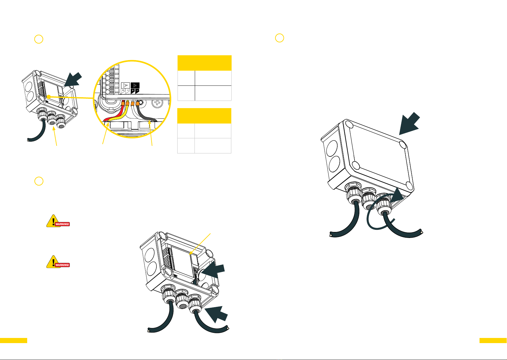
NB! A waring symbol indicates that extra care must be taken.
Damage to equipment and/or injury can occur. Please read all
warnings before installing this product.
Zenitel takes no responsibility for damages caused by improper or inadequate
mounting and installation.
Important mounting and installation considerations
• These products must be installed where its weight can be fully supported.
• If using anchors, plugs or screws other than those specified by Zenitel, they
may not be able to hold the weight of the product, and this may cause a
safety hazard.
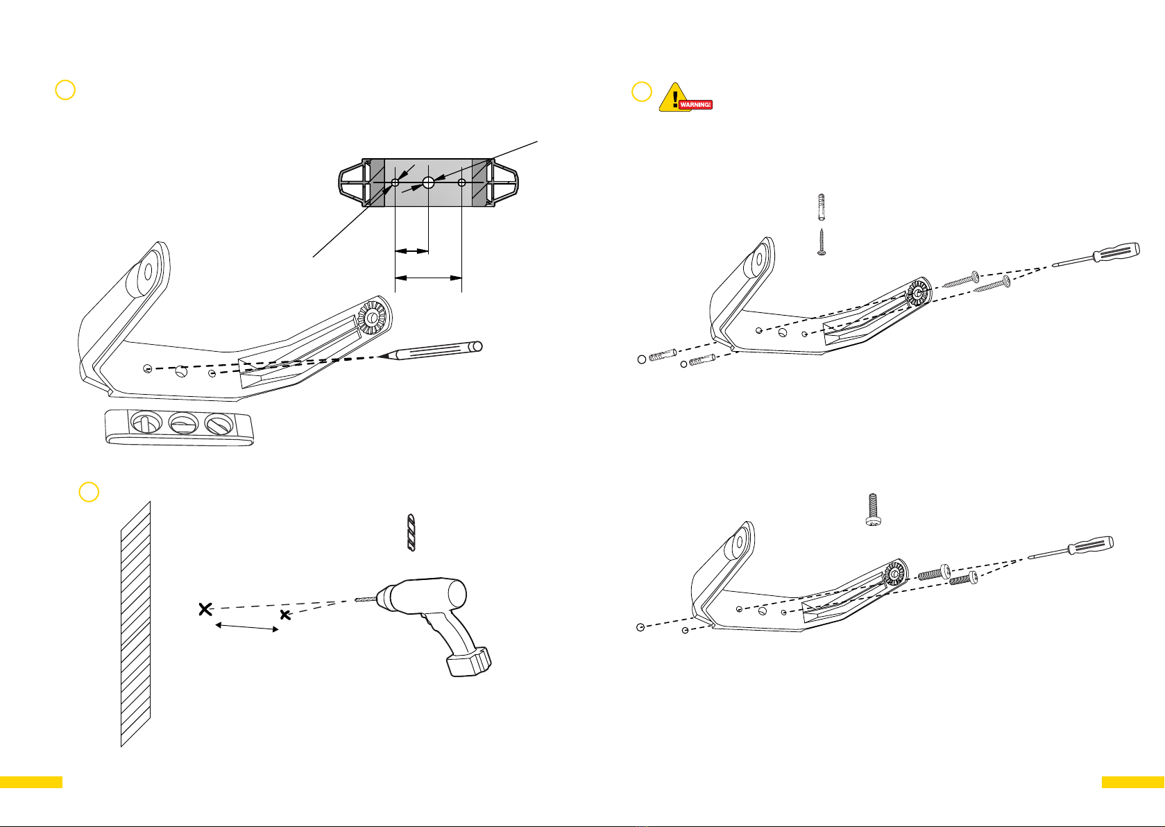
• When drilling holes in wall, pole or plate, make sure you use a drill with
the specified diameter. Make sure that you also follow the instructions
regarding the depth of the holes.
• Make sure that all screws are fully tightened. Applying excessive force to
the screws may damage your wall or cause damage to the product.
• Do not place a unit in environments with a high level of dust, heat, moisture
or vibration.
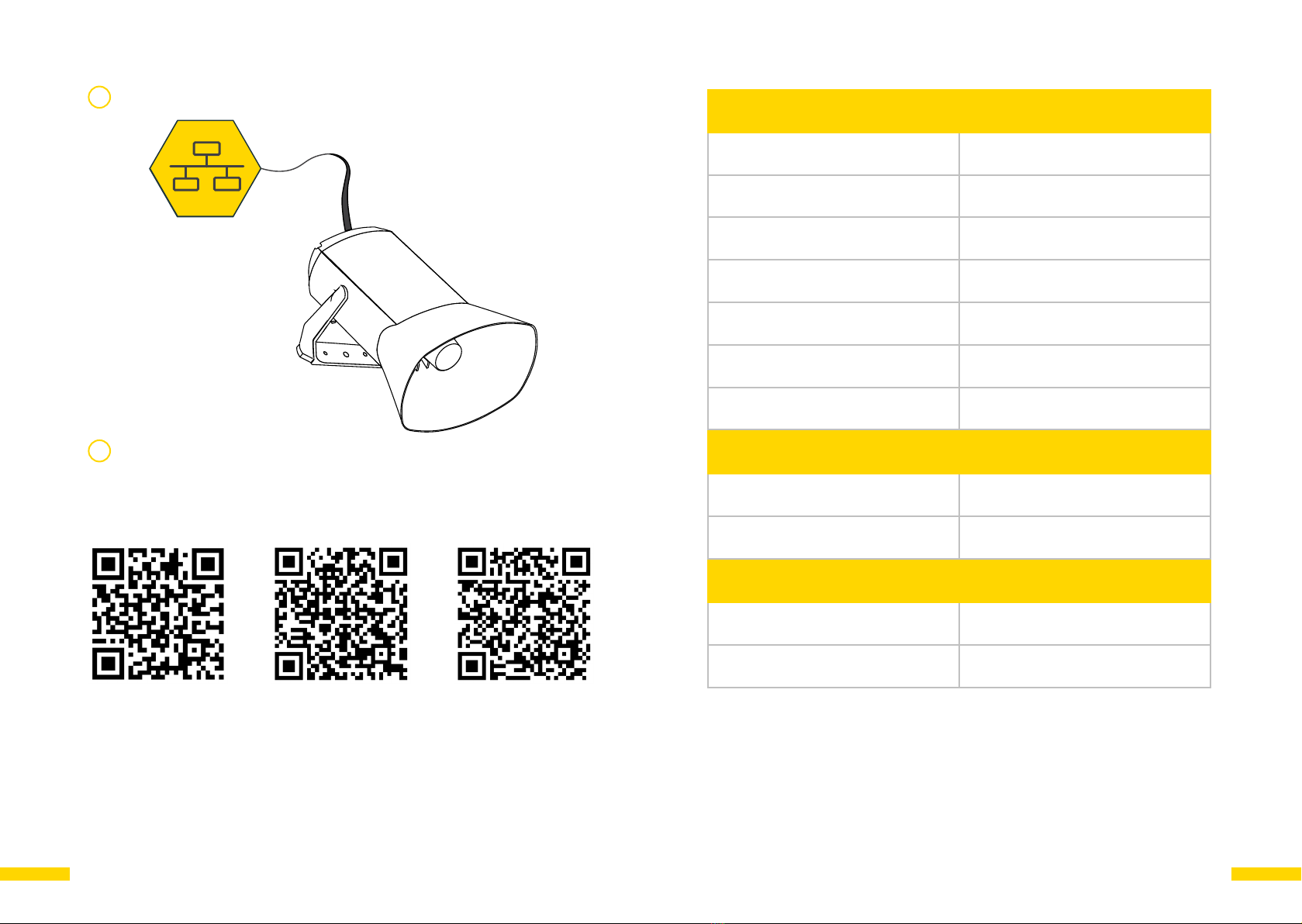
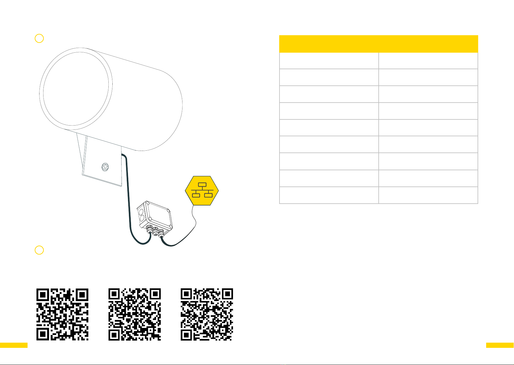
• Installation of all speakers must be done using shielded Ethernet cables
with grounding at the switch end.
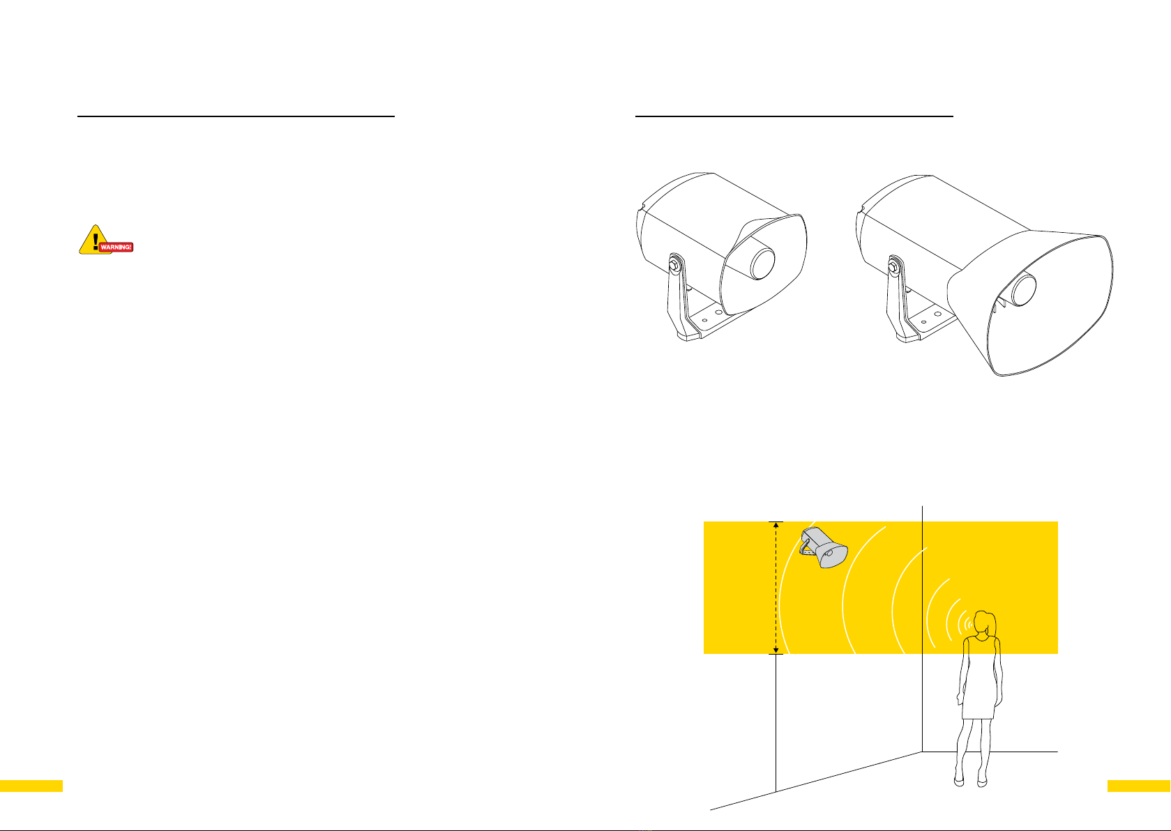
2 ELSII-10HM / ELSII-10LHM
ELSII-10HM ELSII-10LHM
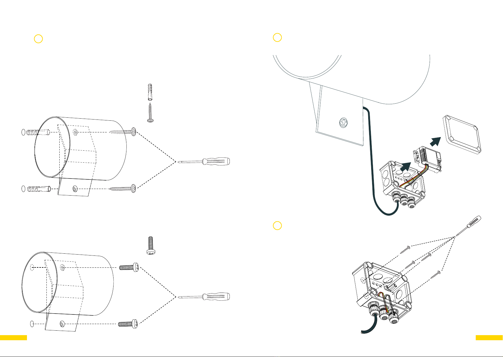
Mounting & Installation of ELSII-10HM / ELSII-10LHM
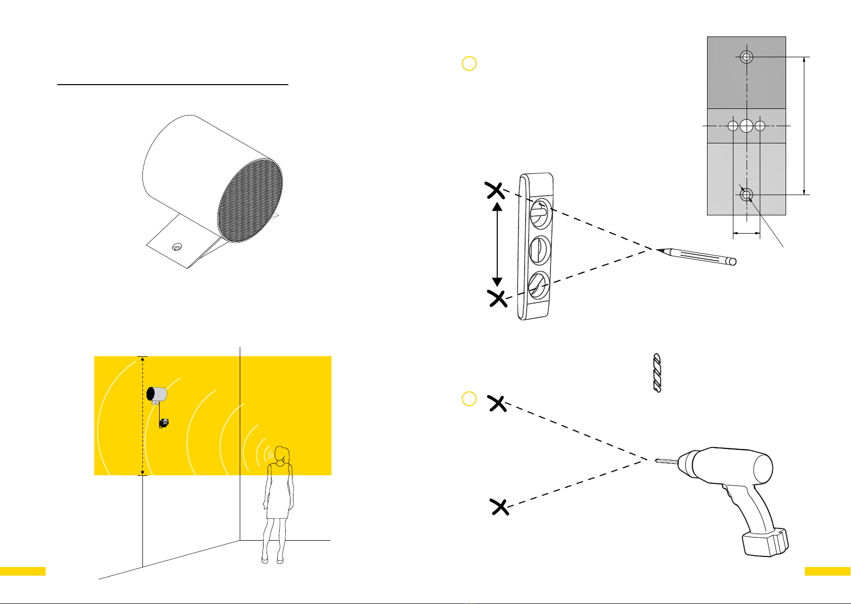
Mount the speaker at a height between 1,5-3 m for optimal placement of the speaker
microphones’ ability to detect voices.
Min. 1,5 m
Max. 3 m