P9
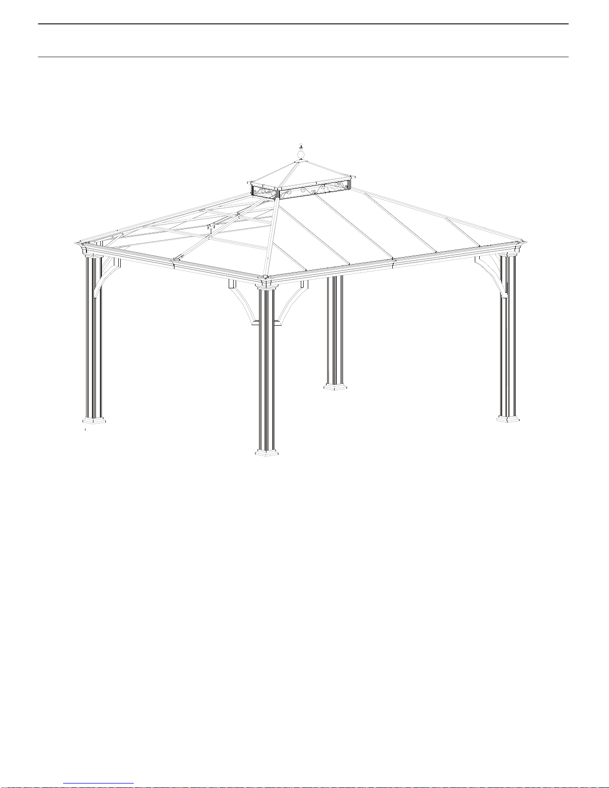
ALUMINUM HARDTOP GAZEBO ASSEMBLY INSTRUCTION
CUSTOMER SERVICE
Zenith Industries, LCC warrants to the original purchaser that this item is free from defects in work-
manship and materials of your item provided the item was factory-sealed at the time of purchase and
is maintained with care and used only for personal, residential purposes. The item is warranted to be
free from defects in material or workmanship for a period of 1 year. Should any manufacturing
defect arise within this warranty period, Zenith Industries, LLC will repair or replace (at our option)
any defective merchandise upon proof of purchase receipt with date at no charge to the customers for
replace parts and labor; however, transportation and delivery costs, remain the responsibility of the
purchaser. A purchaser of an "open box," previously-returned, or "clearance" item, as well as original
purchasers outside of the warranty period, may obtain replacement parts from Zenith Industries for
products in current production, at nominal cost.
If you are within the return policy that most stores have, you do have the option of returning this item
back to the store which you bought it from for an exchange of the same item, or a refund of the
purchase.
If you are within or beyond the return policy that most stores have, and need tech. assistance or
replacement parts, please call Zenith Industries, LLC at 1(855)-6-ZENITH from 9:30 am to 6:30 pm
eastern standard time or e-mail to
s[email protected] or fax your part
s replacement order
form together with the purchase receipt to 1 (513) 217-9415 for assistance.
CARE & Maintenance
Our steel components for garden accessories and furniture are treated with rust inhibiting paint that protects it from
rusting. However, due to the nature of steel, surface oxidation (rusting) will occur once these protective coatings
are scratched. This is a natural process and is not a defect! To minimize this condition, we recommend care when
assembling & handling the product to prevent scratching the paint. Should any scratching or damage occur, we
Surface rust can also
recommend immediate touch-up with rust inhibiting paint. be easily removed with a very light
application of common cooking oil. If surface oxidation (rusting) occurs and if no measure is taken to prevent this,
the oxidation may start dripping on to deck or patio and caused damaging stains,
which may be difficult to remove.
This can be prevented if the measure is taken to keep the product from oxidizing.