GB-10
EXZ2610DL
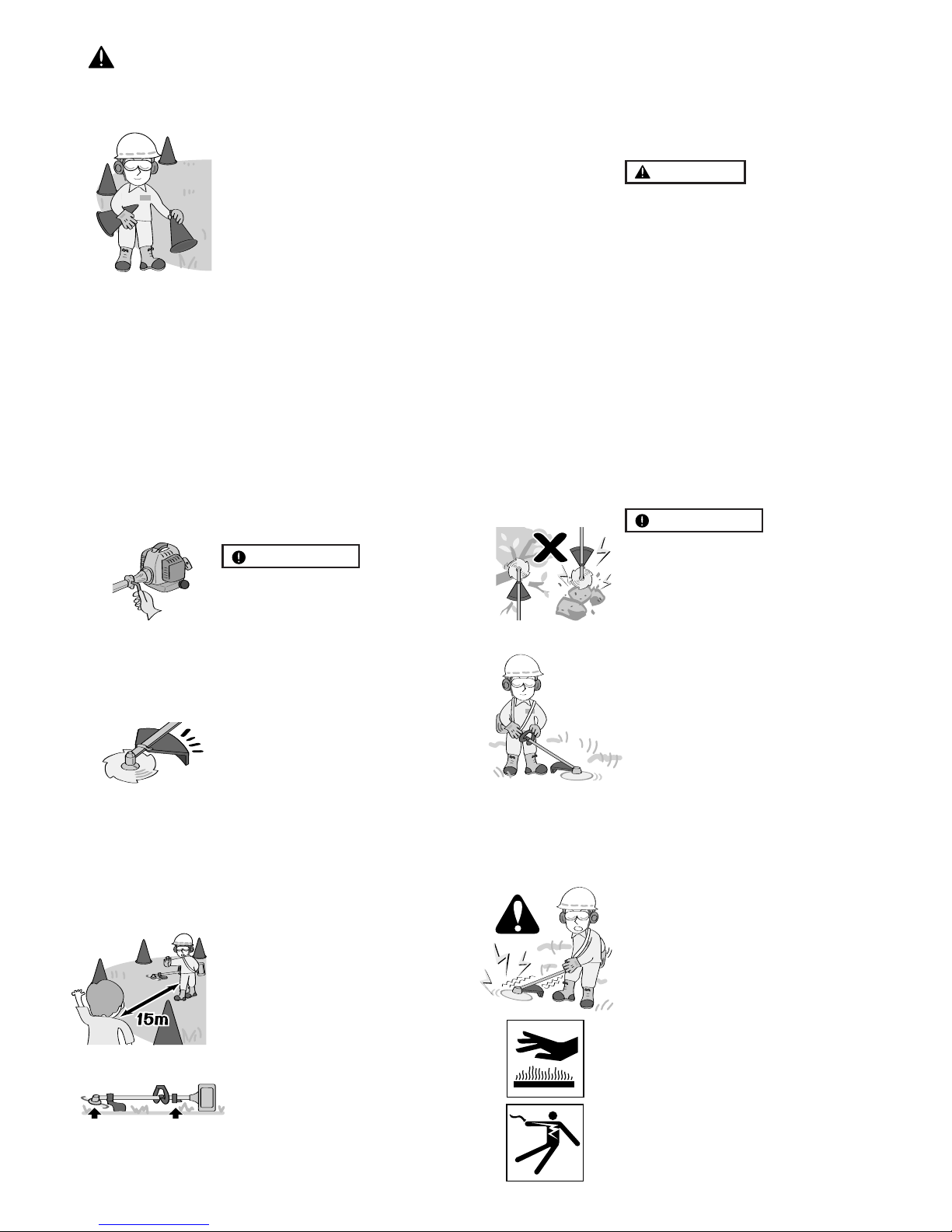
1. When you finish cutting in one lo-
cation and wish to continue work
in another spot, turn off the en-
gine, lift up the unit and carry it
paying attention to the blade.
2. Never forget to place the protec-
tive cover over the blades.
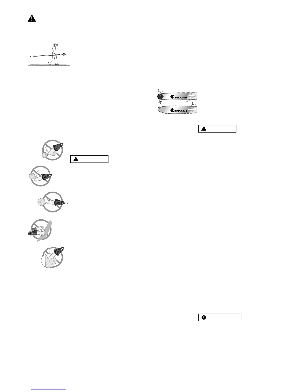
3. When hand-carrying the product,
cover over the cutting attachment
if necessary, lift up the product
and carry it paying attention to the
cutting attachment.
4. Never transport the product over
rough roads over long distances
by vehicle without removing all
fuel from the fuel tank. If doing so,
fuel might leak from the tank dur-
ing transport.
KICKBACK SAFETY PRECAU-
TIONS FOR CHAIN SAW USERS
WARNING
•Kickback may occur when the
nose or tip of the guide bar
touches an object, or when the
wood closes in and pinches the
saw chain in the cut. Tip contact
in some cases may cause a light-
ning fast reverse reaction,kicking
the guide bar up and back to-
wards the operator. Pinching the
saw chain along the top of the
guide bar may push the guide
bar rapidly back towards the
operator. Either of these reac-
tions may cause you to Iose con-
trol of the saw, which could re-
sult in serious personal injury.
•Do not rely exclusively on the
safety devices built into your saw.
As a chain saw user you should
take several steps to keep cut-
ting jobs free from accident or
injury.
(1) With a basic understanding of
kickback you can reduce or
eliminate the element of surprise.
Sudden surprise contributes to
accidents.
(2) Keep a good grip on the saw with
both hands, the right hand on the
rear handle, and the left hand on
the front handle, when the engine
is running. Use a firm grip with
thumbs and fingers encircling
the chain saw handles. A firm
grip will help you reduce kick-
back and maintain control of the
saw.
(3) Make certain that the area in
which you are cutting is free from
obstructions. Do not let the nose
of the guide bar contact a log,
branch, or any other obstruction
which could be hit while you are
operating the saw.
(4) Cut at high engine speeds.
(5) Follow the manufacturer’s sharp-
ening and maintenance instruc-
tions for the saw chain.
(6) Only use replacement bars and
chains specified by the manufac-
turer or the equivalent.
WARNING
•Make sure the chain and sprocket
are correctly adjusted before op-
erating the pruner (see page
13~14 for adjustment proce-
dures). Never attempt chain ad-
justment with the engine running!
•Always make sure the cutting at-
tachment is properly installed and
firmly tightened before operation.
•Never use a cracked or warped
guide bar: replace it with a ser-
viceable one and make sure it fits
properly.
•If a saw chain should bind fast in
a cut, shut off the engine immedi-
ately. Push the branch or tree to
ease the bind and free the saw
chain.
•Do not operate the pruner with the
muffler removed.
•When cutting a limb that is under
tension, be alert for springback so
that you will not be struck by the
moving limb.
•Always stop the engine immedi-
ately and check for damage if you
strike a foreign object or if the ma-
chine becomes tangled. Do not
operate with broken or damaged
equipment.
IMPORTANT
•Do not make unauthorized modi-
fications or substitutions to the
guide bar or chain.
•Never allow the engine to run at
high RPM without a load. Doing
so could damage the engine.
•Keep the pruner as clean as pos-
sible. Keep it free of loose veg-
etation, mud, etc
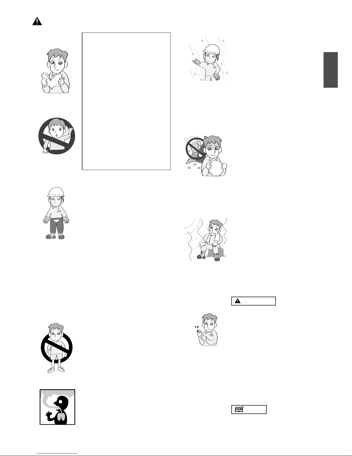
5. For safe operation
(PS-EX only)