manuals.online logo
Brands
  1. Home
  2. •
  3. Brands
  4. •
  5. Zephyr
  6. •
  7. Ventilation Hood
  8. •
  9. Zephyr Okeanito COK-E42SX Installation guide

Zephyr Okeanito COK-E42SX Installation guide

iiim
C
wwwzephyronline.com
Okeanito
CO K-E36SX
CO K-E42SX
CO K-E48SX
Model number:
Serial number:
Date of Purchase:
Sales Dealer:
00COK-70001 07/05Rev:2Q Zephyr Corporation.
SAFETYNOTICE........................................................................................................................2
LiSTOFMATERIALS...........................................................................................................3
iNSTALLATION
Ducting Calculation Sheet ......................................................................................4
Mounting Height and Clearance .......................................................................5
Ducting .....................................................................................................................................6
Specifications .....................................................................................................................7
Internal Blower ...................................................................................................................8-9
Preparing Hood for External Blower ..............................................................10-1 2
Mounting the Hood .......................................................................................................13
Attaching Utensil Rail...................................................................................................14
External Blower Specifications ...........................................................................15
External Blower ................................................................................................................16-1 ?
FEATURES&CONTROLS
Controls Overview ..........................................................................................................18-19
C
C
0
ro
N,=,
0
m
MAINTENANCE
Cleaning ..................................................................................................................................20
Lights .........................................................................................................................................21
TROUBLESHOOTING.......................................................................................................22
WARRANTY...............................................................................................................................23
LISTOFACCESSORIES/PARTS.............................................................................24
EXPLODEDVIEWDIAGRAM.....................................................................................25-26
READ AND SAVE THESE INSTRUCTIONS
Ill
O
Z
WARNING
TO REDUCE THE RISK OF FIRE OR ELECTRIC SHOCK, DO NOT USE THIS FAN WITH ANY SOLID-STATE
SPEED CONTROL DEVICE.
WARNING
_1t TO REDUCE THE RISK OF FIRE, ELECTRIC SHOCK, OR INJURY TO PERSONS, OBSERVE THE FOLLOWING:
a. Use this unit only in the manner intended by the manufacturer, If you have questions, contact the manufacturer.
I_ b. Before servicing or cleaning unit, switch power off at service panel and lock the service disconnecting means to prevent power from being
_1=== switched on accidentally.
When the service disconnecting means cannot be locked, securely fasten a prominentwarning device, such as tag, to the service panel.
CAUTION
For General Ventilating Use Only. Do not Use to Exbaust Hazardous or Explosive Materials and Vapors.
Take care when using cleaning agents or detergents.Suitable for use in household cooking area.
_'_ WARNING
TO REDUCE THERISKOFARANGETOP GREASE FIRE:
a. Never leave surface units unattendedat high settings. Boilovers cause smoking and greasy spillovers that may ignite. Heat oils slowly on low
or medium settings.
b. Always turn hood ON when cooking at high heat or when cooking flambeing food (i.e. Crepes Suzette, Cherries Jubilee, Peppercorn
E Beef Flambe)
c. Clean ventilating fans frequently Grease should not be allowedto accumulate on fan or filten
d. Use proper pan size. Always use cookware appropriatefor the size of the surface element.
WARNING
TO REDUCE THE RISK OF INJURY TO PERSONS INTHEEVENTOFARANGETOPGREASEFIRE, OBSERVE THE FOLLOWING:
a. SM OTHER FLAMES with a close-fitting lid, cookie sheet, or metal tray, then tu rn off the burner. BE CARE FUL TO PREVENT BUR NS.
If the flames do not go out immediatel_EVACUATE AND CALL THE FIRE DEPARTME NT.
b. NEVER PICK UP A FLAMING PAN - You maybe burned.
c. DO NOT USE WATE R, includingwet dishcloths or towels- a violent steam explosion will result.
d. Use an extinguisherONLY if:
1. You know you have a class AB C extinguisher, and you already know how to operate it.
2. The fire is small and contained in the area where it started.
3. The fire departmentis being called.
4. You can fight the fire with your back to an exit.
S. Based on "Kitchen Fire Safety Tips" published by NFPA.
WARNING
TO REDUCETHE RISKOF FIRE ELECTRIC SHOCK OR INJURY TO PERSONS, OBSERVE THE FOLLOWING:
a. Installation Work and -lectrica Wiring Must De Done by Qualified Person (s) In Accordance with all Applicable Codes and Standards,
Including Fire-Rated Const, uction.
b. Sufficient air is needed for proper combustion andexhausting of gases throughthe flue (chimney) of fuel bumingequipmentto prevent back
drafting. Followthe heating equ@mentmanufacturer's guideline and safety standards such as those published by the National Fire Protection
Association N FPA and the American Societ, for Heating, Refrigeration, and Air ConditioningEngineers (AS H R AE) and the local code authorities
c. When cutting or drilling into wall or ceiling do not damage electrical wiring and other hidden utilities.
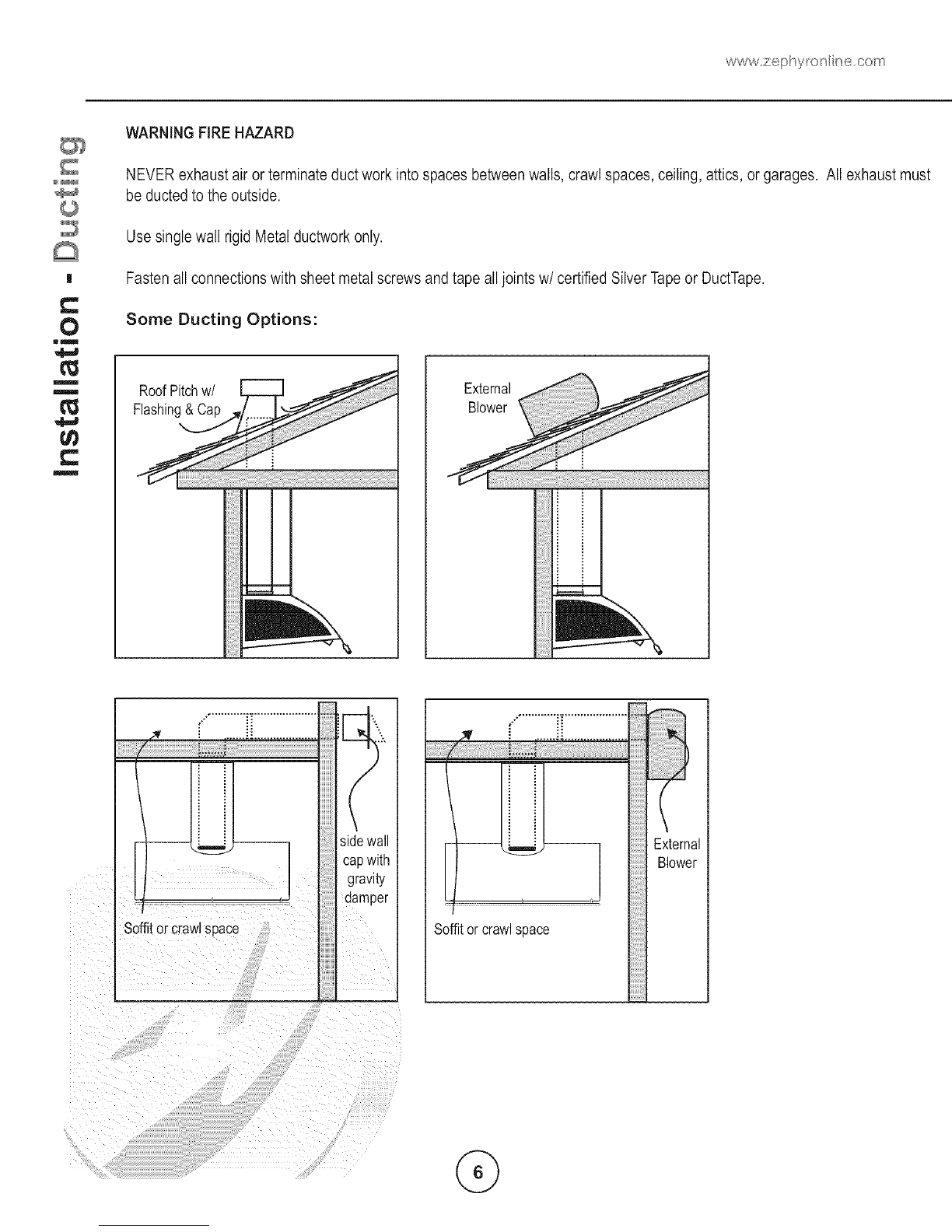
d. Ducted fans must always ventto the outdoors
WARNING
TO REDUCE THE RISK OF FIRE, USE ONLY METALDUCTWORK,
CAUTION
To reduce risk of fire and to properlyexhaust air. be sure to duct air outside - Do not vent exhaust air into spaces within walls or ceilings or into
attics crawl spaces or garages.
CAUTION
To Reduce the Risk of Fire and Electric Shock. Install This Range Hood Only with Remote Blower Models C BE-IO00 Rated
Maximum6,2 amp, 120 Vac 60Hz or Jntecjral Blowers Manufactured by Zephyr Ventilation, Models CB 1-600.
MODEL: COK-ExxS
1 - Hood
1 - Baffle Filter (2 on 48" model)
2 - 50W 120V Halogen Light Bulbs GU-IO
2 - 40W 120V Appliance Bulbs
1 - Utensil Rail
2 - Telescopic Duct Covers
1 - Ceiling Mounting Bracket (pre attached to duct cover)
1 -Wall Mounting Bracket
1 - HARDWAREPACKET
T - 2" Wood Screws
T - Anchors
7 - 1/2" Washers
4 - 1/2" Screws 5xl 5ram
4 - 10mm Washers
1-SMALLHARDWAREPACKET
1 - Tool
3 - Short Set Screws (4 on 48" Model)
1- HARDWAREPACKET,EXTERNALBLOWERKIT
1 - 8" Collar
1 - External Blower Wiring Box with Wires
10 - 1/2" Self Tapping Screws
10 - 4ram Internal Diameter Washers
m
lm
O
lm
_3
NODUCTINGiSPROVIDED
EXTERNALANDiNTERNALBLOWERSOLDSEPARATELY
Make sure to remove the protective film off of the hood before installation in order to make removal of the film
easier. Be careful not to scratch the stainless steel while installing.
C
0
lm
m
m
C
m
Duct pieces i Equivalent number
31/4"x10" 1Ft. x( ) =l
Rect.,
straight
Ft.
Duct pieces i Equivalent number
- ::length x used = Total
__ 6" Round 30 Ft. x ( ) = Ft.
wall cap
with damper
e .... 7" Round, i 1 Ft. x ( ) = Ft.
straight _ roof6"Round,cap ii30 Ft. x ( ) = i Ft.
7" Round, i Ft. x ( ) = Ft. 6" round to 1 Ft. x ( ) = Ft.
straight
31/4"x10" 15Ft. x( ) = Ft.
Rect. 9@
elbow
3 1/4" x 10" i 9 Ft. x( ) = Ft.
_ Red. 450
elbow
................. i ......
3 1/4" x 10" i 30 Ft. x ( ) Ft.
_ ech
wall cap
with damper
_ijma 3 1/4" x 10" i 5 FL x( ) Ft.
Rech to
6" round
transition
3 1/4" x 10" 15Ft. x( =i Ft.
Rect. to i
6' round i
transition
900 eibo'_
6" Round. 1E Ft. -- Ft.
900 eJbo_
6" Round. 9 Ft Ft.
(_ 450 elbow
Subtotal column 1 = Ft.
3 1/4" x 10"
rect.
transition
6" round to 16 Ft. x ( ) = Ft.
3 1/4" x 10"
rect.
transition
900 elbow
_ i 7" Round, 5 Ft. x ( ) = Ft.
900 elbow
7" Round, 9 Ft. x ( ) = Ft.
450 elbow
7" Round 30 Ft. x ( ) = Ft.
wall cap
with damper
._j_} 7" Round, 30 Ft. x ( ) = Ft.
roof cap
7" round to 8 Ft. x ( ) = Ft.
[_ 3 1/4" x 10"
rect.
transition
Subtotal column 2 =i
Subtotal column 1 =!i
Total ductwork =
Ft.
Ft.
Ft.
Maximum Duct Length: =or satisfactor air movemem
[ne total ouc_ let ]in of a 3 1/4" x 10" rectangJlar. 6" or 7"
olameter rouna auct should not exoeea 100 eau_valent feet.
Min 32" Max 52"
141/2"
Min28" Max36"
36"
Min 96" Max 124'
Minimum mount height between range top to hood bot-
tom should be no less than 28".
Maximum mount height should be no higher than 36".
It is important to install the hood at the proper mounting
height. Hoods mounted too low could result in heat
damage and fire hazard; while hoods mounted too high
will be hard to reach and will loose its performance and
efficiency.
If available, also refer to range manufacturer's height
clearance requirements and recommended hood
mounting height above range. Always check your local
codes for any differences.
DUCTING
A minimum of 6° round or 3-1/4 x 10"
rectangular duct work must be used to maintain
maximum air flow efficiency with the 600 cfm
internal blower A minimum ofl0"to 8" round must be
used with the 1000 cfm external blower.
Always use rigid type metal duct work only.
Flexible ducts could restrict air flow by up
to 50%.
Use calculation worksheet to compute total
duct work.
ALWAYS,when possible, reduce the number
or transitions and turns. Ifa reducer is used,
install a long reducer instead of a pancake
reducer. Reduce duct size as far away from
opening as possible.
If turns or transitions are required:
Install asfar away from opening and as far
apart, between 2,as possible.
DAMAGE-SHIPMENT INSTALLATION:
• Pleasefully inspect unit for damage
before installation.
• If the unit is damaged in shipment, return
the unit to the store in which it was bought
for repair or replacement.
• If the unit is damaged by the customer
repair or replacement is the responsibility
of the customer,
If the unit is damaged by the installer (if
other than the cus_omert, repair of replace
ment must be made by arrangement
between customer and installer.
C
0
ml
m
!
C
WARNING FIRE HAZARD
NEVER exhaust air or terminate duct work into spaces between walls, crawl spaces, ceiling, attics, or garages. All exhaust must
be ducted to the outside.
|
0
mm
m
m
C
m
Use single wall rigid Metal ductwork only.
Fasten all connections with sheet metal screws and tape all joints w/certified SilverTapeor DuctTape.
Some Ducting Options:
[
:!
Soffitor crawlspace
' I
da pe
-- _- External
Blower
Soffitorcrawlspace
193J
193/4"
10"
36,42,48
141/2"
117/8"
22 5/8"
_" -36"-
8"-42"
3 1/2"-48"
15"
©
C
0
gl
m
!
C
m
85/16"
93/16"
ATTENTION
The following are intructions for installing internal blower model CBI-600. For instructions on preparing for external
blower model CBE-1000 please turn to page "10". Before installing, verify that motor spins freely,
€
O
lm
m
m
C
m
The internal blower kit consists of the blower
and capacitor box with wiring.
1. Position blower as shown.
2. Attach blower to flange as shown using
the provided 1/2" 5x15mm screws with
washers.
3. Position capacitor box as shown.
4. Secure capacitor box TOhOOd using the
provided 1/2" self tapping screws.
5.Removeexistinggroundingscrewand
attachgroundingwirefromcapacitorbox.
7.Attachshortcapacitorconnectortoblower
connector,
6.Re-attachgroundingscrewtofinish
installationofcapacitorbox.RefertoFig-Aon
previouspage,
8.Attachlongcapacitorconnectortocontrol
boardconnector.
m
|
C
0
Iml
m
m
C
m
9. Use plastic tie to hold wiring together. 10. Remove wood block
Final view of internal blower install.
Continue to page "12" for hood installation instructions.
ATTENTION
The following are intructions on preparing your hood for installation with external blower model CBE-1000.
For instructions on installing internal blower model CBI-600 please turn to page "8".
The external blower kit consists of an 8"
collar, and external blower wiring box. The
external blower is purchased separately.
1. Remove screws from internal flange.
C
O
lm
m
m
C
m
2. Remove internal flange from hood. 3. Position 8" collar as shown.
4. Attach 8" collar to qood as shown using 5. Attach external blower wiring box to top of
Drovluec 1/2" self tapping screws, hood using provided 1/2" self tapping
screws.
6.Positioncoverontoexternalblower
wiringbox. 7.Securecovertoboxwithprovidedscrew.
8.Attachconnectorfromexternalblower
wiringboxtocontrolboardboxconnector
insidehood. 9.Attachgroundingwirefromexternalblower
wiringboxtogroundingscrewofthejunction
box.ReferonFig-Aindiagrambelow.
C
O
Im
m
m
C
I
10. Final view of external blower preparation
Continue to page "1 2" for hood installation instructions and page
"15" for external blower installation instructions.
_1@
C
O
ml
m
m
C
m
DuctCover
CeilingBracket
m
m
T
D/L
I
I
B ff
C _21"
I
I
I
C/L
141/2"
min28"
max36"
DuctCover
CeilingBracket
C/L Attachscrewsto
ceilingbracket
1. Measure from cooking surface to hood bottom, level and mark line A.
2. Plum and mark center line.
3. Mark mounting height, line B (14 1/2" from line A). This is the top of the hood.
4. Measure up, 7 1/2" from line Aand mark mounting spread from C/L Line C. (21")
5. Follow center line up to the ceiling, measure and mark 6" from the wall. Make sure the spot you mark is still
on the center line. This is where the center of the duct cover ceiling bracket will mount.
6. Place duct cover ceiling bracket onto ceiling and mark the (2) holes where screws will be attached. If attaching
bracket to drywall only, drill and insert provided anchors into the marked holes. Cut out inside diameter of the
ceiling bracket to fit the 6" or 8" round duct work. Attach bracket to ceiling with (2) screws provided.
7. Prepare duct work and electrical.
All Electrical work must be performed by a qualified electrician or person with similiar
z_ technical know and background.
For personal safety, remore house fuse or open circuit beaker before beginning installation.
C3C
Do not use extension cords or adapter plug with this appliance.
._ Follow National Electrical Codes or prevailing local codes and ordinances.
<Electr ca Supply
cc
_- This appliance requires a 120V 60Hz electrical supply, and connected to an individual, properly grounded branch
Jw circuit, protected by a 15 or 20 ampere cicuit breaker or time delay fuse. Wiring must be 2wire with ground.
w Pleasd refer to Electrical Diagram labeled on product.
@
_p
gap between
bracket and
wall
C I°°°°°°°°°°°°°°°°°°°°°i
Bottom
Attach screws to both
sides of the duct covers
and secure to ceiling bracket.
\
A
C
0
mm
m
m
C
m
Electrical
1. Place wall bracket on line C. Position top of wall bracket so it is even with the 21" mounting spread Make
sure bracket is attached to wall as shown in the diagram. The top of Tnewal 9racKel snoula nave a gap between
it and the wall, The bottom should be flush against the wall. Use (3) 2" wooa screws Tc aTTacnuracKeT tO wa Use
anchors if not mounting to studs.
2, Lift hood onto wall bracket, there is a lip on the back of the nooa wnlcn wl rest on tne wa Bracket. Secure Jn
place by *screwing (2) screws with washers through hood into Tnewal. There are two noleB at Tne DOTTOmnslde
the hood in which to do this,
3. Place telescopic duct covers on top of hood and extend top duct :over to Tnecemng bracKeT.AtTacn auct co er to
ceiling bracket with the provided screws.
4. Run duct work down to top of motor, Attach electrical wiring from :emng to wrong on ToF of _noTornouslng. _sude
duct cover up towards ceiling to gain access to the motor housing)
*Note: If installing onto drywall only with no wall studs present, attach EZ anchors (not provided) into the wall.
Please see page 15 for external blower installation instructions.
C
0
lm
m
m
C
m
Front Back
1. Attach utensil rail to hood canopy. A small hole has been pre-drilled into the canopy to provide a starting point
to attach the first utensil rail post. After the first post is lined up with the hole, gently slide the rest of the rail onto
the canopy, (note: be careful not to scratch the stainless steel when performing this step, this is why there is a
starter hole),
2, Attach a short set screw into each post in order to hold utensil rail onto canopy.
NOTE:
The following instructions describe the installation of the CBE-1000 external blower for use with Zephyr models CTR
COK or CSH range hoods only,
Fig-5
2'_
24 II
/
I>d[_71/2"
811
55/8" 10
_1 5/8"
/4"
3/4"
30"
10"Elbow
10"Duct
ROOFMOUNT
Fig-1
TYPICALiNSTALLATiON
10"Elbow
Hood
OUTSIDEWALLMOUNT
OutsideWall
C
O
mm
m
m
C
m
Recommended for use only over conventional domestic gas and electric ranges,
C
O
IIm
m
m
C
m
1. Remove and discard shipping brackets and wood support (attached to sides of motor and inlet collar). Fig. - 7
BEFORE INSTALLING, check to see if blower wheel turns freely and does not rub on motor brackets. Check damper door
to be sure it moves freely and spring returns door to closed position,
2. Provide 14" x 18" hole through the roof or wall as shown in Fig. - 2. For reference, location of 10" duct connection and
wiring connection is shown.
Install blower on roof or wall, with discharge
(screened end) pointing down, according to
standard roofing procedures.
NOTE: Front discharge edge should be on top
of shingles and rear and side edges under shingles.
Unit must be sealed between roof or wall and under
side of flange with roofing mastic to prevent leaks.
For installation on a flat roof, or roofs with pitch
of less than 1 1/2' in 12", install blower on curb
as shown in Fig, - 3, Position curb on sloping roof
with 2" dimension facing down slope. Position curb
on flat roofs so that discharge points away from
prevailing wind.
Fig-7
101/2"
11/2'J
Fig-2
14" ,_-
I
I
I
I
_8"
TopView
DownSlope
of
Roofor Wall
Remove
Remove Fig-3
4. Connect the blower toexhaust system with a 10"diameter metalduct only. Use 10"adjustable elbow to adjust to roof
angle. IMPORTANT: Run 10" round duct work from the external blower to the ceiling, Before the duct work passes
through the ceiling bracket, use a 10" to 8" transition adapter (included with external blower) and run 8" duct work
to the opening on the hood. The 8" duct work run should not exceed 60" in length. (see Fig 4a)
Blower
Tapeand screw all joints to prevent air leaks. See Fig- 4.
ShingleOver Flashing 10"AdjustableElbow
ShingleUnder Flashing 10"DiameterDuctWork
Conduit
IScrewandTa#6J6int
Ceiling
/
5. Removetop cover of blower to access wiring connections. Retain mounting screws.
6. Run electrical conduit per localcode to conduit outlet in bottom plate of blower (use liquid tight connection). Other end of
conduit will connect to external blowerwiring box in you Zephyr hood. See installation instructions earlier in manual for
wiring location.
7. Run(5) wires in conduit (1 black, 1 white, 1 blue, 1 red and 1 green ground) between the blower and hood. Check for
local code compliance for style and gauge of wires. The ground wire shall have a suitable gauge according to the
ElectricalCode and Local Regulations. See Fig. -6 for wiring details. These wires will connect to the external blower
wiring box on top of the hood.
CAUTION: Before wiring the unit, switch poweroff at service panel and lock the service disconnecting means to prevent
power from being switched on accidentally.
8. Replacecover onto blower from step 5 and secure with screws provided. All screws must be in place on cover.
O
mm
m
m
m
Fig- 6
CBE-1000: W(R)NG DIAGRAM
External Blower
Wiring Box
(hood) d_
White(common) r--" --1
Black (high) JJunction Boxl
(CBE.IOoo>(
Red |
Green (_qround}
CBE-1000:1/2 liP 3 - Speed Motor. 115VAC, 60liz/15 Amp Circuit Required
@
©
i
m©
C
©
O
:3
LI,.
O Blower On/Off O Display (Speedlevel,DelayOff Indicator, FilterClean/Change)
J
Adjust 3Speed Levels MoodLight On/Off
Lights On/OfflHoldto Dim
15 Min Delay Off
1. Blower On/Off
8, the blower is switched On and Off.
By pressing
2. Speed Selection
The 3 speed levels are selected by pressing @ to decrease and 1-'(,-_,)to increase speed level.
The display indicates level selected. v
3, Delay Off
This is used for programmed shut down of blower and lights 15 minutes after the function is activated.
Press once, a dot flashes in the lower right hand side of display_'] indicating the function is on.
The hood wilt completely shut down in 15 minutes.
4. Lights On/Off/Dim
Switch lights On and Off by pressing (_) once. To dim lights, press and hold (a#_'_for 2 seconds.
5. Advance Display Functions
6. iVloodLight On/Off
This switch turns the mood lights On and Off. Press IN to turn on, press again to turn OFF.
Filters Clean Reminder (Metal):
After every 30 hours of use, the display will start flashing an_ reminding you to clean the baffle
filters from residue and possible clogs.
®

This manual suits for next models

2

Other Zephyr Ventilation Hood manuals

Zephyr ALU-E63 Operating and maintenance manual

Zephyr

Zephyr ALU-E63 Operating and maintenance manual

Zephyr Genova Series User manual

Zephyr

Zephyr Genova Series User manual

Zephyr Z1C-00TI User manual

Zephyr

Zephyr Z1C-00TI User manual

Zephyr Optica Island EOT-E42ASX Installation guide

Zephyr

Zephyr Optica Island EOT-E42ASX Installation guide

Zephyr AK7000AS Installation guide

Zephyr

Zephyr AK7000AS Installation guide

Zephyr Verona ZVO-E30AG Installation guide

Zephyr

Zephyr Verona ZVO-E30AG Installation guide

Zephyr Pisa ZPI-E30AG Installation guide

Zephyr

Zephyr Pisa ZPI-E30AG Installation guide

Zephyr ALL-M90BBX Operating and maintenance manual

Zephyr

Zephyr ALL-M90BBX Operating and maintenance manual

Zephyr Breeze II AK1200x Installation guide

Zephyr

Zephyr Breeze II AK1200x Installation guide

Zephyr AK6536 Installation guide

Zephyr

Zephyr AK6536 Installation guide

Zephyr ZRG-E30AS Installation guide

Zephyr

Zephyr ZRG-E30AS Installation guide

Zephyr Trapeze CTP-E48BSX Installation guide

Zephyr

Zephyr Trapeze CTP-E48BSX Installation guide

Zephyr Edge Wall AED - M90ASX User manual

Zephyr

Zephyr Edge Wall AED - M90ASX User manual

Zephyr Milano Wall ZMI-M90BS Installation guide

Zephyr

Zephyr Milano Wall ZMI-M90BS Installation guide

Zephyr ACT Siena ZSI-E30BS-ES Installation guide

Zephyr

Zephyr ACT Siena ZSI-E30BS-ES Installation guide

Zephyr Roma Groove ZRG-E30BS Installation guide

Zephyr

Zephyr Roma Groove ZRG-E30BS Installation guide

Zephyr Siena ZSI-E30AS-ES Installation guide

Zephyr

Zephyr Siena ZSI-E30AS-ES Installation guide

Zephyr Pisa ZPI-E30AG290 Installation guide

Zephyr

Zephyr Pisa ZPI-E30AG290 Installation guide

Zephyr LAYERS WALL DLA-E42ASSX User manual

Zephyr

Zephyr LAYERS WALL DLA-E42ASSX User manual

Zephyr Gust AK7100AS Installation guide

Zephyr

Zephyr Gust AK7100AS Installation guide

Zephyr Pisa ZPI-E24AG Installation guide

Zephyr

Zephyr Pisa ZPI-E24AG Installation guide

Zephyr ZMD-E42AS Installation guide

Zephyr

Zephyr ZMD-E42AS Installation guide

Zephyr AK2000 Installation guide

Zephyr

Zephyr AK2000 Installation guide

Zephyr Milano Wall ZMI-M90BS Installation guide

Zephyr

Zephyr Milano Wall ZMI-M90BS Installation guide

Popular Ventilation Hood manuals by other brands

Miele DA 5341 D installation instructions

Miele

Miele DA 5341 D installation instructions

Jenn-Air JVR0436HS Installation Instructions and Use & Care Guide

Jenn-Air

Jenn-Air JVR0436HS Installation Instructions and Use & Care Guide

Faber MATRIX Features & dimensions

Faber

Faber MATRIX Features & dimensions

Franke DB 10078 Instructions for use and installation

Franke

Franke DB 10078 Instructions for use and installation

Franke FDB 10078 I Instructions for use and installation

Franke

Franke FDB 10078 I Instructions for use and installation

Küppersbusch EMI 850.0E operating instructions

Küppersbusch

Küppersbusch EMI 850.0E operating instructions

AEG DBE5970M user manual

AEG

AEG DBE5970M user manual

AVG AVN-308CS2 owner's manual

AVG

AVG AVN-308CS2 owner's manual

AEG DI 8821 Operating and installation instructions

AEG

AEG DI 8821 Operating and installation instructions

Pkm 8090GZ instruction manual

Pkm

Pkm 8090GZ instruction manual

Electrolux EFP 6400 Operating and installation instructions

Electrolux

Electrolux EFP 6400 Operating and installation instructions

Novy 661 installation instructions

Novy

Novy 661 installation instructions

NEFF D5655X0 Operating and installation instructions

NEFF

NEFF D5655X0 Operating and installation instructions

FALMEC ALBA 760 Instruction booklet

FALMEC

FALMEC ALBA 760 Instruction booklet

Franke FBI 537 XS User instructions

Franke

Franke FBI 537 XS User instructions

Indesit HD 79 Instructions for installation and use

Indesit

Indesit HD 79 Instructions for installation and use

Ekolos EVL30SW Use & care and installation manual

Ekolos

Ekolos EVL30SW Use & care and installation manual

Parmco RLCD-6G-1000L Installation and operating instructions

Parmco

Parmco RLCD-6G-1000L Installation and operating instructions

manuals.online logo
manuals.online logoBrands
  • About & Mission
  • Contact us
  • Privacy Policy
  • Terms and Conditions

Copyright 2025 Manuals.Online. All Rights Reserved.