Zerica Kolumna User manual

Kolumna
OPERATION
AND MAINTENANCE MANUAL
Touch / Button
Thirstyfor innovation
MANU 15.04.20

2
1.
2.
3.
4.
5.
6.
7.
8.
9.
10.
INTRODUCTION
UNPACKING
2.1 Box Content
2.2 Description of the appliance
INSTALLINGTHE UNIT
3.1 Stand-alone installation
3.2 How to x the Kolumna directly to a counter
FIRST POWER-ON
4.1 Turn on the tablet
4.2 Connect the machine to the internet
4.3 Launch Zerica app
BASIC SETTINGSTABLET (TOUCH MODEL ONLY)
5.1 Entering the settings area
5.2 Settings
5.3 Cold Drinks
5.4 Schedule
5.5 Pricing
5.6 Alerts
5.7 Technical
5.8 Install
5.9 Exiting the settings area
MAINTENANCE
6.1 Main maintenance tasks
6.2 On-screen monitoring and warning messages (touch model only)
DEMOLITION AND DISMANTLING
WARRANTY
EC DECLARATION OF CONFORMITY
DECLARATION DM 174/2004

3
Thank you for choosing a Zerica® water dispenser.
Using the appliance is simple, however before connecting, operating or
modifying settings on the unit, please read this manual completely.

4
1
.
INTRODUCTION
ATTENTION: For the correct use of this appliance, we recommend that you carefully read
these instructions and that you keep them for future reference.
This manual is an integral part of the appliance and must accompany the product even if it is
transferred or sold after rst installation.
Theseinstructionsareintendedtoprovideinformationregardingcorrect installationandoperation.
Its disclosure to all interested parties is a prerequisite for correct operation and protection from
possible accidents and damage to the appliance and injury to third parties.
The presence of such warnings does not imply that the manufacturer assumes any liability for
any damage to property or injury to third parties caused by the use of the device, which has all
the original certications required in order to make it suitable for the use for which it has been
designed, as well as safe to use in compliance with applicable standards.
The reproduction of the contents of this manual for distribution to third parties is strictly forbidden
without the express prior consent of the manufacturer Zerica S.r.l.
AVVERTENZE GENERALI
This appliance is not intended for use by persons (including children) with reduced physical,
sensory or mental capabilities, or lack of experience and knowledge, unless they have been
given supervision or instructions concerning the use of the appliance by a person responsible
for their safety.
Children must be supervised to assure that they do not play with the machine.
The appliance must not be installed near water sprays.
The appliance must not be cleaned with water sprays.
The appliance needs to be installed on a at surface.
Do not install this unit in environments with temperatures lower than +3 °C as internal freezing
of the water inside the product will permanently damage the water circuit.
This appliance generates a noise level below 70 dB.
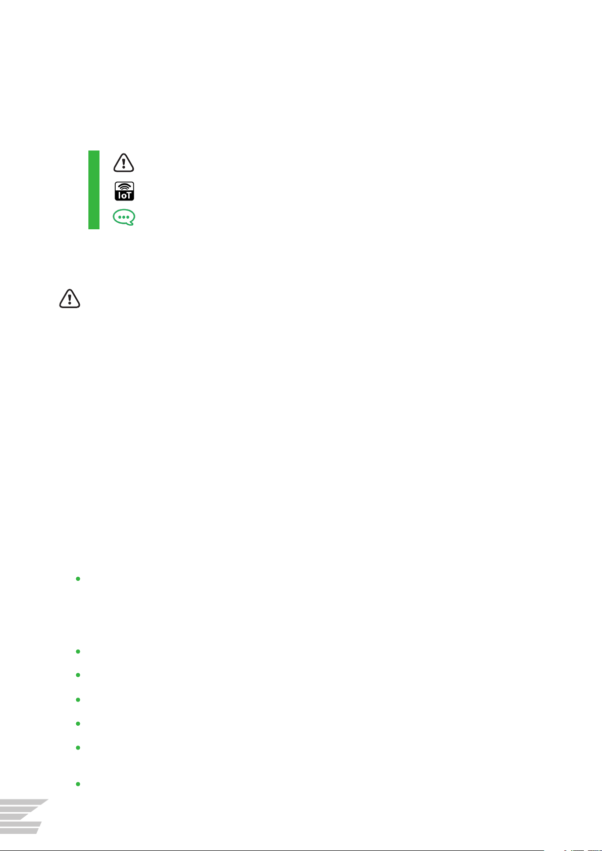
General warnings
Notes and explanations
IOT enabled functionality
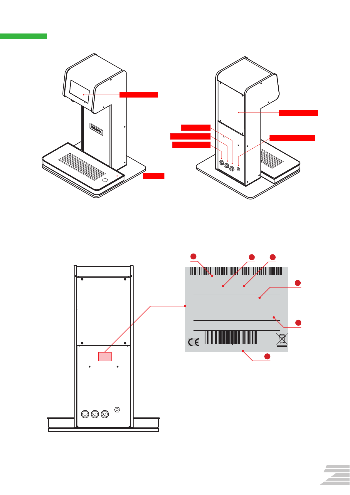
LABELS

5
ATTENTION: The installation and maintenance of the appliance must be carried out by
professionally qualied personnel, in compliance with the standards and regulations
in force, since incorrect installation can cause damage to people, animals and things for
which the manufacturer cannot be held responsible.
ATTENTION: The data and characteristics indicated in this manual do not bind the
manufacturing company, which reserves the right to make all the modications it
deems appropriate, without the obligation of warning or replacement.
ATTENTION: Keep this booklet for future reference.

6
2.
UNPACKING
The packaging must be disposed of by the customer in accordance with current environmental
protection regulations.
Place the appliance in the upright position which can be
easily identied by the direction mark“UP”on the box;
Open the package and check that there are no dents
or obvious damages to the appliance caused by
transportation;
In case of obvious defects or dents, do not install the
appliance.
1 2
5
6
7
8
9
3
4
20mm
Ø 6mm
Ø 6,5mm
60mm
Ø 6mm
Touch version Button version
#
1
2
3
4
5
6
7
8
9
Qty
1
1
1
1
1
4
4
4
4
Item
Kolumna touch / button
Raccogligocce
Base intermedia 3mm
Base supporto 8mm
Alimentatore
Rondella Ø 6,5mm
Vite mm 20
Vite mm 60
Piedino adesivo in gomma
Cod.
COLOE 0201 / 0101
RACOGO023
SL COLOE 10 03
SL COLOE 10 02
ALIM006
RONDP102
VIT12107
VIT12105
PIEDN 010
Note: Any defects must be notied within 24 hours of delivery.
Drip tray
Intermediate base plate 3mm
Base plate 8mm
Power supply
Washer Ømm 6.5
Adhesive rubber foot
Screw mm 20
Screw mm 60
2.1 BOX CONTENT

7
XXX X000 X0000
__V __W
IP__
000000
Manual
0000
Inlet Water
Min__ MPa - Max__ MPa
12 3
1. Model
2. Power supply voltage
3. Watts
4. IP rating
5. Minimum and maximum mains water pressure
6. Serial number
4
5
6
The identication plate is located on the rear of the system, and it includes the following
technical details:
2.2 DESCRIPTION OF THE APPLIANCE
Device Identication
Drip tray
IN ambient water
IN sparkling water
IN cold water
Power supply socket
Touchscreen IOT
Removable panel

8
3.1 STANDALONE INSTALLATION
Interpose the additional intermediate base plate (2), between the unit and the base plate (3),
as shown in the picture, and connect the three parts using the screws (1).
Stick the adhesive rubber feet (4) at the corners of the base plate.
3
.
INSTALLING THE UNIT
ATTENTION: The installation and maintenance of the appliance must be carried out
only by authorised, professionally qualied and trained personnel, and after having
disconnected the power supply.
1
Come installare Kolumna alla base in plexiglass
20mm
Ø 6mm
1
2
1
A
2
A
2
Front side
Back side
3
4
4
3
3. IN acqua ambiente
24V DC
2. IN acqua frizzante
1. IN acqua fredda

9
1
Come installare Kolumna alla base in plexiglass
20mm
Ø 6mm
1
2
1
A
2
A
2
Front side
Back side
3
4
4
3
3. IN acqua ambiente
24V DC
2. IN acqua frizzante
1. IN acqua fredda
3.2 HOW TO FIX THE KOLUMNA DIRECTLY TO A COUNTER
In order to x the Kolumna to a counter, you will need to drill holes into the counter to allow
passage of cables and pipes, and for the xing screws.
Follow these steps:
Place the plexiglass base plate in the
desired position.
Use the base plate as a guide to mark
the points to be drilled on the work
surface.
Remove the plexiglass base plate.
Drill the holes with a drill or similar
appropriate tool.
1.
2.
3.
4.
4
3 5
6
2
1
(1). Smontare il pannello destro
svitando le quattro viti per accedere
all’interno della macchina.
(2). Staccare i tubi idrici e la presa di
alimentazione attraverso l’apertura
laterale, e collegare i tubi a quelli di
prolunga con gli adeguati raccordi
(non inclusi nella confezione).
(3) Posizionare la base in
plexiglass nel punto in cui si
desidera ssare la macchina.
(4) Usare la base come guida per
disegnare con una matita i punti
da forare sul piano di lavoro.
(5) Togliere la base.
(6) Eseguire i fori con un trapano
o altri utensili idonei.
Come installare Kolumna direttamente al banco di lavoro
1
B
2
B
3
2
1
IN acqua ambiente
IN acqua frizzante
IN acqua fredda
3
2
1
1
24
3
1. IN cold water
24V DC
2. IN sparkling water
3. IN ambient water
Place the Kolumna on a at surface
and connect the water supply lines as
shown in the picture.
Connect the unit to the power supply.

10
Remove the right panel by unscrewing the ve access screws.
Disconnect the water connections from the back panel and the power supply and pass them
through the square hole on the right side of the machine.
Connect the pipes to the extensions with the appropriate ttings (not supplied with the
Kolumna).
5.
6.
7.
4
3 5
6
2
1
(1). Smontare il pannello destro
svitando le quattro viti per accedere
all’interno della macchina.
(2). Staccare i tubi idrici e la presa di
alimentazione attraverso l’apertura
laterale, e collegare i tubi a quelli di
prolunga con gli adeguati raccordi
(non inclusi nella confezione).
(3) Posizionare la base in
plexiglass nel punto in cui si
desidera ssare la macchina.
(4) Usare la base come guida per
disegnare con una matita i punti
da forare sul piano di lavoro.
(5) Togliere la base.
(6) Eseguire i fori con un trapano
o altri utensili idonei.
Come installare Kolumna direttamente al banco di lavoro
1
B
2
B
3
2
1
IN acqua ambiente
IN acqua frizzante
IN acqua fredda
3
2
1
5
6
7
IN cold water
IN sparkling water
IN ambient water

11
Interpose the additional intermediate base plate (3) (as shown in the picture) between the
counter and Kolumna.
Pass the water pipes and the power supply cable through the central hole.
Fix the Kolumna to the pre-drilled worktop using the screws (2) and washers (1) provided.
8.
9.
10.
(7) Interporre la base
intermedia (seguendo il verso
indicato in gura) tra
Kolumna e il piano di lavoro,
e far passare i tubi idrici e la
presa di alimentazione
attraverso il foro centrale.
Inne ssare il tutto al piano
utilizzando le viti e le rondelle
fornite.
(8) Completare l’installazione
accoppiando correttamente i tubi
degli ingressi idrici di Kolumna ai
rispettivi tubi delle uscite
dell’impianto di refrigerazione.
Collegare l’alimentatore alla
relativa presa.
Kolumna è pronta per essere usata.
2
60mm
Ø 6mm
1
2
1
1Ø 6,5mm
3
B
4
B
78
3
Front side
Back side
3
2
1
8
3
10
9

12
Complete the installation by correctly coupling the Kolumna water inlet pipes to the
respective outlet pipes of the refrigeration system.
Connect the power supply.
The Kolumna is now ready to be used.
11.
12.
(7) Interporre la base
intermedia (seguendo il verso
indicato in gura) tra
Kolumna e il piano di lavoro,
e far passare i tubi idrici e la
presa di alimentazione
attraverso il foro centrale.
Inne ssare il tutto al piano
utilizzando le viti e le rondelle
fornite.
(8) Completare l’installazione
accoppiando correttamente i tubi
degli ingressi idrici di Kolumna ai
rispettivi tubi delle uscite
dell’impianto di refrigerazione.
Collegare l’alimentatore alla
relativa presa.
Kolumna è pronta per essere usata.
2
60mm
Ø 6mm
1
2
1
1Ø 6,5mm
3
B
4
B
78
3
Front side
Back side
3
2
1
11
12

13
230 V
230 V
1 2
3
4.1 TURN ON THE TABLET
Connect the power supply (A) to the mains.
Press button (B) (on the “P”version of the unit) until the screen turns on.
In versions of the unit with a little hole at the front, please use the pin provided (D) into the
hole as shown in the drawing (C). Press down until you perceive a slight “click” and keep
pressing until the screen turns on.
4.
FIRST POWER-ON
1
2
3
B
D
C
1
Come installare Kolumna alla base in plexiglass
20mm
Ø 6mm
1
2
1
A
2
A
2
Front side
Back side
3
4
4
3
3. IN acqua ambiente
24V DC
2. IN acqua frizzante
1. IN acqua fredda
A

14
Click on the icon to launch the app.
4.2 CONNECT THE MACHINE TO THE INTERNET
The unit can work without connection to the internet. However certain operations such as
modifying the day schedule (e.g. Normal, Locked or Sleep / Energy Saving modes) can only be
performed via the internet.
Note: This functionality can be enabled if the system is connected to the internet (via 4G SIM
or Wi-Fi). All WEB features are available through a subscription plan. Our sales oce is at your
disposal for further information.
This unit can be connected to the internet via Mobile network or Wi-Fi network.
Our sales department is at your disposal for more information on how to install your SIM or for
the purchase of a new SIM.
If you are using Wi-Fi, connect the tablet to a local Wi-Fi using the tablet’s standard Settings.
Wi-Fi connectivity can be also set-up later from within the app.
4.3 LAUNCH ZERICA APP
The Zerica app should launch automatically after a few seconds, but it can be also launched
directly from the tablet’s Home screen. Launch the Zerica/BeviLaNatura app.

15
5.1 ENTERING THE SETTINGS AREA
5.
BASIC SETTINGS TABLET (TOUCH MODEL ONLY)
A B
C
D
E
F
Tap on the ZERICA logo on top of the screen (A) to display the monitoring area (B).
Note: The monitoring area shows the estimated remaining lter life (lowest % left of remaining
days or remaining litres) if present (C), the percentage of residual capacity of the CO2cylinder (if
present) (D), the notications dialog (E), the settings icon (F).
Touch the settings icon (F).
Enter the password. There are three passwords with increasing level of permissions:
775533 - day-to-day operations only, including CO2reset and CO2purge.
123666 - ability to change temperature, dispensing portion size, and to reset lter life.
Note: There is a third password reserved to technicians and installers.
Please contact Zerica’s technical support to obtain this password.
To exit the “Settings” area, see the next section.
1
2
3
4

16
5.2 SETTINGS
On this screen you can:
Disable / enable a specic drink using the “available” check boxes (A). Disabled drinks will not
be available for selection to the end customers.
Select the language (B).
View the quick manual (C).
Click on the ‘COLD DRINKS’Tab (D) to proceed with additional settings.
Click on ‘Done’ to exit the Settings area (E).
5.3 COLD DRINKS
On this screen you can:
Select the dispensing option Glass OR Jug (A);
Set up the cup and jug portion size (B);
C
D
A
BE
1
2
B
A

17
Setting automatic dispensing portion size
Change dispensing portion size in ml for the glass and jug/carafe options using the + and -
buttons (B):
Place a cup or jug in the dispensing area;
Touch the ‘Test’ button (C) to dispense a sample;
Calibration of the water portions can be performed using the ‘Calibrate’ button (D).
This task should be performed only after purging the CO2water circuit.
Selecting drink dispensing option
Choose Glass OR Jug to select the preferred serving size (A).
Note: The unit has a dispensing accuracy >95% on all lines. Sparkling water dispensing dose is strongly
modied by CO2bubbles.
A
Sparkling calibration
To calibrate the dosage use the buttons (B) and and test for accuracy (C).
D
C
B
C
B

18
5.4 SCHEDULE
Note: This functionality can be enabled if the system is connected to the internet (4G SIM or Wi-Fi).
All WEB features are available through a subscription plan. Our sales oce is at your disposal for
further information.
The unit has 3 operating modes (A) which can be set independently for each of the twelve
2-hour slots in the day (00:01-02:00, 02:01-04:00, etc) (B):
Normal: Normal operation mode, all drinks will be available for selection.
Chilled Water Only: Out-of-hours operation mode, the machine will only dispense chilled
still water.
Sleep - Energy Saving Out-of-hours operation mode, all dispensing is suspended. The
machine will operate in energy-saving mode.
The current schedule can be displayed via the settings area.
Note: The day schedule can only be changed via the Zerica/BeviLaNatura web portal.
5.5 PRICING
Note: This functionality can be enabled if the system is connected to the internet (4G SIM or Wi-Fi).
All WEB features are available through a subscription plan. Our sales oce is at your disposal for
further information.
This section displays the set prices for each available drink.
Note: Prices can only be changed via the Zerica/BeviLaNatura web portal.
BA

19
5.6 ALERTS
The ‘Alerts’ tab displays a log of recently generated warnings / error messages.
Click on ‘Refresh’ (A) to refresh the list.
Click on ‘Clear’ (B) to clear the existing log.
Warning triangle sign
A yellow triangle sign will appear on the top right corner of the screen every time there is a
new warning message.
!
BA

20
5.7 TECHNICAL
On the left side of the screen you will be able to display a log of all information related to the
machine including:
Dispensed volumes by drink type;
Current settings (portion size, dispensing option, etc);
Running totals for lter and CO2canister;
Key maintenance dates.
Additional operations
On this screen you will be able to:
Flush the dispensing lines;
Purge the CO2circuit;
Reset CO2usage counter;
Reset Filter usage counters;
Reset service maintenance date;
Change screen brightness on specic times of the day.
Note: Flush and CO2purge operations will be guided step-by-step on screen.
A.
B.
C.
D.
E.
F.
A. Flush
Press this button when you want to perform the purge of the water lines using the step-by-
step wizard.
B. CO2circuit purge
Press this button when you want to carry out the procedure to purge the sparkling water
line. This function is useful for example to remove any air present in the system, due to the
reduction of mixing of CO2with water, and restore the right balance of CO2pressure inside the
carbonator.
With perfectly purged water circuit and without air bubbles, the carbonator will reach full
eciency after about 24 hours of use.
Note: Any presence of air left inside the carbonator will be removed during the delivery of sparkling
water whose carbonation level will improve with the use of the product itself.
Note: The presence of air inside the water circuit drastically reduces the mixing of carbon dioxide
with water. This condition is highlighted by a whitish colour of the sparkling water supplied that
should be always crystal and clear.
A B CD E F
Table of contents
Other Zerica Water Dispenser manuals
Popular Water Dispenser manuals by other brands

Plumbline
Plumbline 3000 Series owner's manual

Ecodyne Water Systems
Ecodyne Water Systems EP 6130 Installation, operation, maintenance & repair parts

American Bio-Systems
American Bio-Systems BioMop User information

Haws
Haws H1119.8 Installation, operation & maintenance instructions

Fetco
Fetco HWB-10 Technical bulletin

Elkay
Elkay VRC8WSJO Installation and use manual