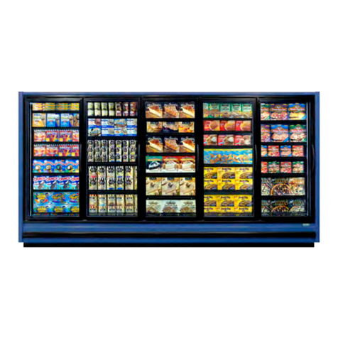
Zero Zone HYBRID Instruction manual

ZERO ZONE
HYBRID™MEDIUM & LOW TEMP
DISPLAY CASE
Installation, Operation & Maintenance Manual
Compliant with 2012 DOE Regulations
MN-01-H • MAR 2015

II
This manual is specic to the Zero Zone Hybrid™ display case.
For standard Zero Zone display case installation and operation, please refer
to the Zero Zone Medium & Low Temp Display Case Installation & Operation Manual.

III
Table of Contents
ZERO ZONE WARRANTY ............................................................................................................... IV
Limited Warranty .......................................................................................................................IV
Extended Warranties .................................................................................................................IV
Length of Extended Warranty ...................................................................................................IV
Product Not Manufactured By The Seller .................................................................................IV
Limitation and Exclusion of Warranties .....................................................................................IV
PLANNING ........................................................................................................................................ 1
DELIVERY ......................................................................................................................................... 2
Case Delivery Through 80" Door ................................................................................................ 2
SETTING THE CASE ........................................................................................................................ 3
Contents Shipped Inside of Case ............................................................................................... 3
Positioning Hat Channels............................................................................................................ 4
Dividers Between Cases............................................................................................................. 5
MECHANICAL .................................................................................................................................. 6
Once in Final Location ................................................................................................................ 6
Setting the Condensing Unit ....................................................................................................... 7
Quick Connect Fittings................................................................................................................ 8
Coupling Insulation ..................................................................................................................... 9
ELECTRICAL/CONTROL ............................................................................................................... 10
Electrical Connections .............................................................................................................. 10
Carel Controller Sensor Wires ...................................................................................................11
PLUMBING ..................................................................................................................................... 12
Case Drain Line to Floor Drain ................................................................................................ 12
TRIM OUT ....................................................................................................................................... 13
Installing Drain, Pump & Pan.................................................................................................... 13
ENCLOSED PUMP ......................................................................................................................... 15
CB121LSUL Pump with Brackets ............................................................................................. 15
TRIM OUT ....................................................................................................................................... 19
Setting the Condensate Evaporation Pan................................................................................. 19
Bumper & Kickplate .................................................................................................................. 20
Shroud Assembly...................................................................................................................... 21
OPERATION ................................................................................................................................... 22
Start-Up..................................................................................................................................... 22
Carel Controller Standard Features.......................................................................................... 22
Instructions for Setting the Time ............................................................................................... 22
Turning the Lights On & Off ...................................................................................................... 23
Automatic Hold-Open Doors..................................................................................................... 24
MAINTENANCE .............................................................................................................................. 25
Solid Shelf Installation & Removal............................................................................................ 25
Wire Shelf Installation & Removal............................................................................................. 26
Bottom Electrical Box Wire Colors (VZCH/VCCH Only) ........................................................... 27
Instructions for Condensate Removal Systems with Condensate Evaporation Pan................. 28
Refrigeration Cleaning & Maintenance ..................................................................................... 29
Preventative Maintenance - Condensing Units & Evaporator Coils.......................................... 29
Carel Controller Programming Instructions............................................................................... 30
Carel Controller Low Temp Codes ............................................................................................ 31
Carel Controller Medium Temp Codes...................................................................................... 32
Carel Controller Basic Operations ............................................................................................ 33
Silencing the Carel Temperature Alarm .................................................................................... 34
Conditions that Trigger the Carel Alarm.................................................................................... 35
Condensing Unit Pressure Switch Settings .............................................................................. 36
OPTIONS ........................................................................................................................................ 37
Sound Attenuation Kit & Balloon Guard.................................................................................... 37
End Close-Off ........................................................................................................................... 38
Fan Kit....................................................................................................................................... 38
Shroud Frame Assembly........................................................................................................... 39
Special Louvered Shroud Design ............................................................................................. 41
Optional Disconnect Installation................................................................................................ 46
MANAGER’S EMERGENCY GUIDE .............................................................................................. 47
IV • Zero Zone Warranty
Limited Warranty
Zero Zone, Inc. (Seller) hereby warrants that any products manufactured by it and sold are warranted to be free from defects in material and
workmanship, under normal use and service for its intended purpose, for a period of one (1) year from the date of original installation (not to
exceed 15 months from the date of factory shipment). The obligation under this warranty shall be limited to repairing or exchanging any part,
or parts, without charge, FOB Factory, and which is proven to the satisfaction of Zero Zone’s service department to be defective. Zero Zone
reserves the right to inspect the job site, installation, and reason for failure. This limited warranty does not cover labor, freight, or loss of food or
product, including refrigerant loss. This warranty does not apply to motors, switches, controls, lamps, driers, fuses or other parts manufactured
by others and purchased by the seller unless the manufacturer of these items warrants the same to the seller and then only to the extent of
such manufacturer’s warranty to the seller. Any products sold on an “AS IS” basis shall not be covered by this warranty.
Extended Warranties
In addition to the standard limited warranty, for further consideration, the Company will extend to the original purchaser, a limited extended
warranty on the compressor only, following expiration of the standard warranty. The seller agrees to repair or exchange, at its option, or provide
reimbursement for such exchange as directed, less any credit allowed for return of the original compressor, of a compressor of like or similar
design and capacity, if it is shown to the satisfaction of Zero Zone that the compressor is inoperative due to defects in factory workmanship or
material under normal use and services as outlined by Zero Zone in it’s “Service and Installation” instructions.
Length of Extended Warranty
Any compressor warranty may be extended for an additional four (4) years but such extension must be purchased prior to shipment to be
effective. In those instances on manufactured systems where factory installed “Zero Zone Oil Management Systems” are purchased the original
limited warranty shall be extended automatically to two (2) years total and purchased extended warranties shall be extended automatically for
a total of six (6) years from the date of factory shipment. This warranty is only for the compressor and not for any other associated parts of the
refrigeration system.
Product Not Manufactured By The Seller
The written Warranty, if any, provided by the manufacturer of any part of the refrigeration unit sold by Seller to Buyer, but not manufactured by
Seller, is hereby assigned to the Buyer. However, Seller makes no representation or Warranty regarding the existence, validity or enforceability
of any such written Warranty.
Limitation and Exclusion of Warranties
THE WARRANTIES SET FORTH HEREIN ARE EXCLUSIVE AND IN LIEU OF ALL OTHER WARRANTIES AND REMEDIES WHATSOEVER,
INCLUDING, BUT NOT LIMITED TO, IMPLIED WARRANTIES OF MERCHANTABILITY AND/OR FITNESS FOR A PARTICULAR PURPOSE.
ZERO ZONE WARRANTY

Planning • 1
ENTRANCE & UNLOADING
What is the height of the entryway that the case(s) will need to go through?
Where will the case(s) be unloaded from the truck? Is there room for the case(s) to be unloaded from the truck?
CASE INSTALLATION & MOBILIZATION
Are you able to move the case(s) inside store to nal location?
The condensing unit will produce some noise. Has this been taken into account when identifying the nal location for these case(s)?
Have you considered the door opening/swing and aisle width?
HEAT REJECTION
Has the rejected heat from condensing unit(s) into store been considered?
Do you have adequate room around the case(s) for the condensing unit to be able to reject heat? There should be a 30" minimum
clearance between the top of shroud and the store ceiling.
Options/considerations if the clearance is less than the 30" minimum:
Add egg crates to the store ceiling panels
Add auxiliary fans to dissipate heat
Use louvered case shrouds
Use an alternate shroud height; Zero Zone Engineering must be contacted
ELECTRICAL
Is there suitable voltage?
Is the appropriate circuit breaker installed and available in the store power panel?
Do you want/need an electrical disconnect at the case(s)?
PLUMBING
Will you be using a oor drain? Can the proper slope to the drain be provided?
Will you be using a pump with the Condensate Evaporation Pan system? This setup will add humidity to the store.
SEISMIC RESTRAINTS
Does your permitting require there to be seismic restraints?
HIGH HUMIDITY
Do you need an auxiliary fan system to provide air movement along the back and underneath the case(s)?
Do you need louvered kickplates for air to be able to move underneath the case(s)?
PERMITTING
The case(s) should be permitted as remote equipment.
Always check with the local inspector to make sure your install follows all code requirements.
REMOTE MONITORING
Remote monitoring is an option that is available for the case(s).
PLANNING

2 • Delivery - Case Delivery Through 80" Door
DELIVERY
2 to 5-door cases are fork-liftable from either end of the case.
1-door cases are not fork-liftable through a standard doorway.
ATTENTION FORK TRUCK OPERATOR!
2-Door 24" Cases:
Forks must extend from 20" to no more than 24" under
the case from ends through bases.
2-Door 30" Or 3-Door 24" Standard Or Deep Cases:
Forks must extend from 26" to no more than 30" under
the case from ends through bases.
3-Door 30" Or 4-Door 24" Cases
Use 48" long forks!
Forks must extend from 39" to no more than 43" under
the case from ends through bases.
4 & 5-Door 30" Or 6-Door 24" Cases
Use 48" long forks!
Forks must extend from 44" to no more than 47" under
the case from ends through bases.
Note: Do not damage end of case with fork truck.
1. Remove bracket from back of case. 2. Pull quick connect lines away and down from case.
3. Reposition quick connect lines and reinstall bracket,
once through doorway.
Temperature
Probe Wires
Case Delivery Through 80" Door
Do not place (“leave, store, or hold”) case outdoors in direct sunlight or high ambient temperature.
OVERALL CASE DEPTH IS 40 1/8"

Setting the Case - Contents Shipped Inside of Case • 3
Pump and Pan Assembly
Condensate Evaporation Pan
Hat Channels with 1", 1.75" or 2.5" Bases
Contents Shipped Inside of Case
SETTING THE CASE

4 • Setting the Case - Positioning Hat Channels
SETTING THE CASE
Position hat channels with tape up.
For 3 and 4-door cases, (as shown above left), the center hat channel needs to be angled
to rest on front and back base. Do not locate under drain hub!
For 5-door cases (as shown above right) there are 4 hat channels - position as shown.
In most instances, cases will require leveling by the use of shims. Refer to Display Case
Installation & Operation Manual (Leveling Section).
Positioning Hat Channels

Setting the Case - Dividers Between Cases • 5
SETTING THE CASE
Dividers Between Cases
Clear plexi dividers separate refrigeration
circuits between same-temp cases.
Insulated dividers are provided between medium temp and low
temp cases in lineups. Both types of dividers are factory-installed
prior to shipping.

6 • Mechanical - Once in Final Location
MECHANICAL
If electrical box was removed for entry, put back into position.
2 to 5-Door Shown
Once in Final Location

Mechanical - Setting the Condensing Unit • 7
MECHANICAL
2. Place condensing unit with quick connects facing the back of the case.
3. Avoid scratching the front of the case.
1. Locate quick connects on the back of the case.
Setting the Condensing Unit

8 • Mechanical - Quick Connect Fittings
MECHANICAL
THIS IS THE MOST IMPORTANT PORTION OF THE HYBRID INSTALL
1. Align and pre-lubricate the couplers before connecting.
2. Start with hand tightening.
3. Tighten coupling connections with a wrench until seated or a
denite resistance is felt. Mark a line on the swivel nut and unit.
Using the line as a guide, tighten an additional quarter turn.
(Sealing does not occur until no threads are visible.)
4. After all connections are made, check the couplings for leaks.
Wrench Size Quick Connect Size Torque Values
13/16" 3/8" 10-12 ft./lbs.
1 - 5/16" 1/2" 35-45 ft./lbs.
1 - 5/16" 5/8" 35-45 ft./lbs.
Quick Connect Fittings

Mechanical - Coupling Insulation • 9
MECHANICAL
Coupling Insulation
One pre-cut 4" piece of split insulation (supplied) will be required on each freezer
suction side quick connect coupling as shown. Wire ties will also be provided.

10 • Electrical/Control - Electrical Connections
ELECTRICAL/CONTROL
Case power (top electrical box) brought from condensing unit electrical
box.
2-5 door cases receive 208V 4-wire service; 115/208V-1PH-60HZ; red
and black power, white neutral, green ground.
1-door cases receive 115V 3-wire service; 115V-1PH-60HZ; black power,
white neutral, green ground.
DO NOT ENERGIZE POWER UNTIL ALL COVERS ARE ON ALL
ELECTRICAL BOXES.
Whip for
Condensing Unit
Black, Red (omitted
for 1-door cases),
Blue, White, Green
Case Conduit
See specic wiring diagrams shipped with your case.
Customer Power
Black, Red (omitted for
1-door cases and all
coolers), White, Green
Distribution
Block
Ground Block
Case Temperature
Control Wire
Blue
Condensing Unit
Contactor Coil Wire
Blue
Wago Connector
Case Power
Black, Red (omitted
for 1-door cases),
White, Green
Condensing Unit
Electrical Box - Small
Condensing Unit
Electrical Box - Large
Cooler Electrical Box Freezer Electrical Box
Ground Block
Case Power
Black, Red (omitted
for 1-door cases),
White, Green
Case Temperature
Control Wire
Blue
Condensing Unit
Contactor Coil Wire
Blue
Wago Connector
Electrical Connections

Electrical/Control - Carel Controller Sensor Wires • 11
ELECTRICAL/CONTROL
Carel Controller Sensor Wires
Sensor wires are found on back of the case.
Temperature (Discharge Air) probe located in false ceiling
Evap (Defrost Term) probe located in coil.
One sensor bulb is factory installed in medium temp case. Probe
wires labeled Green & White for Temperature (Discharge Air).
Two sensor bulbs are factory installed in low temp case. Probe
wires labeled Green & White for Temperature (Discharge Air).
Probe wires labeled Orange & White for Evap (Defrost Term).
Connect Sensor Wires
to Wago Connectors
(match label color
to wire color)
Medium Temp Low Temp

12 • Plumbing - Case Drain Line to Floor Drain
PLUMBING
DRAIN LINE
The drain is located at the center of the case in the oor pan. The drain can be reached by removing the
center coil covers and then removing a fan motor. The 1" PVC drain outlet is located at the center front of the
case behind the kickplate.
Install the tee to the outlet pipe and a drain trap to the tee. Plug the open end of the tee using the clean-out
plug supplied with the drain trap kit. The drain line must be pitched away from the case. The tee, drain trap,
and plug are supplied with the case. The factory installs a drain support at the front of the case on all 30"
door cases. We supply a trap support that is eld mounted to the case. The drain trap must be level. The
drain trap should be primed with water after installation.
Note (if applicable): Typically Hybrid cases are equipped with a condensate collection and removal
system which includes a collection pan, pump, oat switch, condensate evaporation pan with heater
element, and connecting tubing.
Case Drain Line to Floor Drain
(If Applicable)

Trim Out - Installing Drain, Pump & Pan • 13
Drain Pan Assembly 2 to 5-Door Drain Trap Assembly
1. Place the drain pan assembly as shown (Fig. 1).
2. Glue drain-trap assembly to drain. Attach drain assembly to case with screws
provided (Fig. 2), except on 1-door which comes pre-attached.
3. Install PVC drain-trap extension/stop (Fig. 3).
4. Do not glue this component, but use the screw provided. This will allow the
extension to be removed should the drain pan need cleaning or service (Fig. 4).
5. Finished assembly 2 to 5-door VZCH/VCCH (Fig. 5).
6. Finished assembly 1-door VZCH/VCCH (Fig. 6).
7. Finished assembly 2 to 6-door VLCH/VMCH (Fig. 7).
8. Attach PVC tubing to check valve and run to Condensate Evaporation Pan.
9. Test to conrm pump and oat switch are operating properly.
TRIM OUT
Installing Drain, Pump & Pan

14 • Trim Out - Installing Drain, Pump & Pan
TRIM OUT
1. 2.
3. 4.
5. 6.
7.
Installing Drain, Pump & Pan

Enclosed Pump - CB121LSUL Pump with Brackets • 15
INSTALLATION INSTRUCTIONS
1.
If case is shipped with 1.75" bases, then case lateral and support brackets will be shipped inside case. Prime and glue case lateral to
elbow underneath case. Fasten bracket to front of foamed fl oor.
CB121LSUL Pump Pump Kit
CB121LSUL PUMP WITH BRACKETS
Installation
SP-5187 Rev B
ZERO ZONE, INC. • 800-247-4496 • ZERO-ZONE.COM
© 2015 Zero Zone, Inc. All Rights Reserved. • FEB 2015
MN-13-A
ENCLOSED PUMP
CB121LSUL Pump with Brackets

16 • Enclosed Pump - CB121LSUL Pump with Brackets
ENCLOSED PUMP
CB121LSUL Pump with Brackets
2 • CB121LSUL Pump with Brackets - Installation
CB121LSUL PUMP WITH BRACKETS
Installation
2. Place clear vinyl tube (from pump kit) over inlet to pump tank. Fasten into place using hose clamp (provided in pump kit).
SP-5187 Rev B
Table of contents
Other Zero Zone Display Case manuals