Zero Z02 Series Quick guide

zero
HOME AUTOMATION
Z02 - SWING GATE
PG1
USER MANUAL AND CONFIGURATION
Z02.REV01.2018
IT | EN | FR
zero
HOME AUTOMATION Z02 - SWING GATE MOTOR
SUPPLY 230-24V

zero
HOME AUTOMATION Z02 - SWING GATE
PG2
zero
HOME AUTOMATION

zero
HOME AUTOMATION
Z02 - SWING GATE
PG3
INDEX
01. SAFETY INSTRUCTIONS
02. OPERATOR
TECHNICAL SPECIFICATIONS
DIMENSIONS
03. INSTALLATION
INSTALLATION DIMENSIONS
INSTALLATION STEPS
TYPICAL INSTALLATION
04. MAINTENANCE
MANUEL RELEASE
05. TROUBLESHOOTING
01. SAFETY INSTRUCTIONS
ATTENTION:
•To ensure the safety of people, it is important that you read all the following instrucons.
Incorrect installaon or incorrect use of the product can cause physical injury and material
damage.
•Keep these instrucons in a safe place for future reference.
•This product was designed and produced strictly for the use indicated in this manual. Any
other use, not expressly indicated here, could compromise the good condion/ operaon of
the product and/or be a source of danger.
•ZERO SRLS. is not responsible for the improper use of the product, or other use than that
for which it was designed.
•ZERO SRLS. is not responsible if safety standards were not taken into account when instal-
ling the equipment, or for any deformaon that may occur to it.
•ZERO SRLS. is not responsible for the safety and proper operaon when using components
not sold by them.
•Do not make any modicaons to the operator components and / or their accessories.
•Before installaon unplug the automasm from the source of power.
•The installer must inform the client how to handle the product in case of emergency and
provide this manual to user.
•Keep remote controls away from children, to prevent the automated system from being
acvated involuntarily.
•The customer shall not, under any circumstances, aempt to repair or tune the operator
.Must call qualied technician only.
•Connect the automasm to a 230V plug with ground wire.
•Operator for outdoor and indoor use.

zero
HOME AUTOMATION Z02 - SWING GATE
PG4
02. OPERATOR
TECHNICAL SPECIFIATIONS
Z02 specicaons are as follow:
962mm || 1162mm || 1562mm
175mm
159mm
647mm || 747mm || 947mm 104mm
DIMENSIONS
Z02 300 || 400 || 600 dimensions are the following:
Z02.400 Z02.400.24 Z02.600 Z02.600.24
Power Supply 230Vac 50/60Hz 24Vdc 230Vac 50/60Hz 24Vdc
Power 180W 60W 180W 60W
Current 1,4 A 1- 3 A 1,4 A 1-3 A
Capacitor 8µF - 8µF -
RPM 1400
Noise level LpA <= 50 dB (A)
Force 2300 N
Operang temperatures -25°C to 65°C
Thermal protecon 120°C - 120°C -
Protecon class IP54
Working frequence 25% INTENSIVE 25% INTENSIVE
Opening me 13-18 seconds 20-28 seconds

zero
HOME AUTOMATION
Z02 - SWING GATE
PG5
03. INSTALLATION
INSTALLATION DIMENSIONS
Z02 specicaons are as follow: The operator Z02 must be installed with a small inclinaon , to
prevent water inltraon through the extension arm.
For this, the front support must be xed to the gate with a height lower than the height of the
rear support. See example below:
Dimension A • Vercal distance from the oor to the top of the rear support .
Dimension B • Vercal distance from the oor to the top of the front support.
Example:
• Set dimension A (this can be any size of your choice).
• Aer you set dimension A, subtract 10mm to nd dimension B.
• If the height of the rear bracket (dimension A)is set at 600 mm, then the height of the front
bracket (dimension B) will be 590 mm (600mm-10mm).
It is very important that these dimensions are respected! Only this way can be
as- sured the correct funconing and durability of the operators!
It is also very important to have a levelled ground/terrain!

zero
HOME AUTOMATION Z02 - SWING GATE
PG6
(EXTERIOR)
Axis of rotation of the
motor, on the front bracket
Axis of rotation of the gate Closingm echanical
(centero ft he door hinge) stopper
Y
W
Distance between the
centers of the holes on th e
X
supports from operator
Axis of rotation of the
motor,on ther ears upport Opening
direction
(INTERIOR)
Opening mechanic al stopper
On the Illustrated diagrams below and are the dimensions for the installaon of the automated
system.
Opening mechanic al stopper
Opening
direction
(EXTERIOR)
Axis of rotation of theg ate
(centero ft he door hinge)
Y
W
Closingm echanical
stopper
X
Axis of rotation of the motor
(INTERIOR)
on thef ront support
Axis of rotation of theD istance between the centers of the
motor,on ther ears upport holeso nt he supports from operator
X Y W
Z02.400 95° 160-200 120-180 695-700
Z02.600 95° 160-300 120-280 900-905
OPENING ANGLE

zero
HOME AUTOMATION
Z02 - SWING GATE
PG7
It is very important that these dimensions are respected! Only this way can be
assured the correct funconing and durability of the operators!
Legend:
Dimension X - Horizontal distance between hinge axis of the door and the rear axle of
the motor.
Dimension Y- Vercal distance between hinge axis of the door and the rear axle of the
motor.
Dimension W - Distance between axis of the motor brackets
01 • Fixing rear support
• The Rear support must be xed to the
pillar or wall using dimensions provided in
the preceding pages.
It can be xed using screws with mechani-
cal bushing or chemical welding process,
or one of your choice since it provides an
appropriate support.
02 • Fixing front support
• The Front support should be xed to the
gate, respecng height dimensions and di-
stance to the rear support.
This may be xed by using screws, welding
process, or to choose another long as it
provides a secure proper support.
INSTALLATION STEPS
X Y W
Z02.400 95° 120-180 120-180 1095-1100
120° 160-180 120-140 1095-1100
Z02.600 95° 120-350 120-200 1495-1500
120° 200-280 120-200 1495-1500
OPENING ANGLE

zero
HOME AUTOMATION Z02 - SWING GATE
PG8
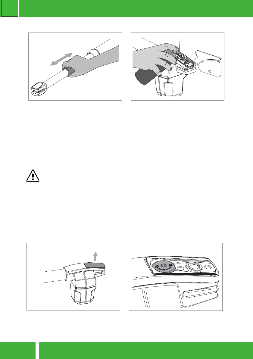
03 • Remove caps and pins from motor
• Before installing motor, remove caps and
pins from motor.
• At the end of the installaon, put back
plasc covers for a beer visual nish of
the operator.
04 • Install operator on the supports
• The operator must be placed on both
supports the same me to avoid
leaving the operator suspended by only
one of the supports.
To make the task easier, you should unlock
the operator in order to be able to stretch
/ retract arm easily,to get the correct posi-
on for supports.
05 • Test movement
• Install the pins removed earlier on each
place with a small amount of lubricant for
less fricon.
•Move the door manually to see if the
door opens and closes uniformly and cor-
rectly, without any irregular fricon during
its enre travel;
This will ensure that operator is not
subjected to problems during operaon.
06 • Connecng operator to control board
and conguring control devices.
•With the operator installed, connect it to
control board for system conguraon (see
control board user manual).
Must also congure the desired control
devices (transmiers, wall switch, etc.) and
other addional components such as an-
tenna, warning light, key selector, among
others.
It is important to respect this installaon order!
Otherwise, it is not possible to ensure correct installaon and operators may not
work properly!

zero
HOME AUTOMATION
Z02 - SWING GATE
PG9
•
INTERIOR
PHOTOCELLS
•
EXTERIOR
PHOTOCELLS
•
MOTOR
•
EXTERIOR
PHOTOCELLS
•
KEY
SELECTOR
•
WARNING
LAMP
•
ANTENNA
• CONTROL
BOARD
TIPICAL INSTALLATION
It is important to use mechanical stoppers in the opening and closing posion of
the gate. If not respected, components of the automaon may suer eorts for
which they were not prepared, and as a result will be damaged.
It is important to use juncon boxes for connecons between motors, components
and control unit. All cables must enter and exit on the boom of the juncon and
control board box.

zero
HOME AUTOMATION Z02 - SWING GATE
PG10
01 • Remove the plasc cap from the rear
end
Informaon engraved on the unlock sha
D=Unlock || B=Lock
• Clean stainless steel arm
• With a cloth soaked in lubricant spray,
wipe any residue that accumulates on the
operator’s stainless steel arm.
• Apply a small amount of spray lubricant
on the arm and using a dry cloth remove
the excess, leaving a homogeneous layer of
lubricant over the arm.
• Lubricate pins
• Remove front and rear caps
• Place a small amount of lubricant on the
holes that contains support pins.
• Install caps on the respecve holders.
04. MAINTENANCE
Check motor supports: Make sure that supports remain well xed on the pillars and
gate to ensure proper funconing of the equipment.
These maintenance measures must be applied every year in order to insure proper
funconing of the automated system.
MANUAL RELEASE
To open manually the gate in case of electric power failure or in case of damage, follow the
below steps:

zero
HOME AUTOMATION
Z02 - SWING GATE
PG11
02 • Insert Release key on the unlock
sha.
03 • Rotate key 180 ° in the direcon indi
cated in the gure to unlock
NOTE : To lock operator so it can work automacally, must do it by turning the key anclockwi-
se.

zero
HOME AUTOMATION Z02 - SWING GATE
PG12
Problem Procedure Behavior Procedure II
Door doesn’t
work
Make sure you have 230V
power supply connected
to control board and if it
is working properly.
Sll not working. Consult a qualied ZERO
technician.
Motor doesn’t
move but makes
noise
Unlock motor and move
the gate by hand to check
for mechani cal problems
on the movement
Encountered problems? Consult an experienced
gate expert.
The gate moves easily? Consult a qualied ZERO
technician.
Motor opens
but doesn’t
close
Unlock motor and move
the gate by hand to closed
posion.
Lock motor again and turn
o power supply for 5 se-
conds. Reconnect it and
send start signal using
transmier.
Gate opened but didn’t clo-
se again.
Check if there is any obsta-
cle in front of the photo-
cells;
Check if any of the control-
devices (key selector, push
buon, video intercom,
etc.) of the gate are jam-
med and sending perma-
nent signal to control unit;
Consult a qualied ZERO
technician.
Gate doesn’t
make complete
route
Unlock motor and move
ate by hand to check for
mechanical problems on
the gate
Encountered problems? Consult an experienced
gate expert.
The gate moves easily? Consult a qualied ZERO
technician.
05. TROUBLESHOOTING

zero
HOME AUTOMATION
Z02 - SWING GATE
PG13
Discovering the origin of the problem
1. Open control board
and check if it has
230V power supply
2. Check input fuses
3. Disconnect the motor
from control board and
test them by connecng
directly to power supply
in order to nd out if they
have problems.
4. If the motor works,
the problem is on the
control board. Pull it out
and send it to our ZERO
technical services for
diagnosis.
5. If the motor doesn’t
work, remove them
from installaon site
and send to our ZERO
technical services for
diagnosis.
Check all moon axis and associated moon systems related with the motor and the gate to nd out
what is the problem.
1. Check capacitors,
tesng operator with
new capacitors;
2. If capacitors are not the
problem, disconnect mo-
tors from control board
and test them by con-
necng directly to power
supply in order to nd out
if they have problems.
3. If the motors work,
the problem is from
control board. Pull it out
and send it to our ZERO
technical services for
diagnosis;
4. If the motors don’t
work, remove them
from installaon site
and send to our ZERO
technical services for
diagnosis
All ZERO control boards have LEDs that indicate the funconing of connecons to allow easy diagnosis
of faults. All safety devices LEDs (DS) in normal situaons remain On. All “START” circuits LEDs in normal
situaons remain O.
If LEDs devices are not all On, there is some security systems malfuncon (photocells, safety edges),
etc.
1 • Close with a shunt all safety systems on the control board (check manual of the control board in
queson). If the automated system starts working normally check for the problemac device.
2 • Remove one shunt at a me unl you nd the malfuncon device .
3 • Replace it for a funconal device and check if the motor works correctly with all the other devices. If
you nd another one defecve, follow the same steps unl you nd all the problems.
1. Check capacitors,
tesng with new ca-
pacitors;
2. If capacitors are not
the problem, discon-
nect motor from con-
trol board and test it
by connecng directly
to power supply in or-
der to nd out if it is
broken;
3. If the motor doesn’t
work, remove it from in-
stallaon site and send to
our ZERO technical servi-
ces for diagnosis.
4. If motor work well
and move gate at full
force during the enre
course, the problem is
from controller. Set force
using P1 buon on the
board. Make a new wor-
king me programming,
giving sufcent me for
opening and closing with
appropriate force.
5. If this doesn’t work,
remove control unit and
send it to ZERO techni-
cal services services.
Check all moon axis and associated moon systems related with the motor and the gate to nd out
what is the problem.
NOTE: Seng force of the controller should be sufcient to make the gate open and close without stop-
ping, but should stop and invert with a lile eort from a person. In case of safety systems failure, the gate
shall never cause physical damaged to obstacles (vehicles, people, etc.).

zero
HOME AUTOMATION Z02 - SWING GATE
PG14
NOTE:
_____________________________________________________________________
_____________________________________________________________________
_____________________________________________________________________
_____________________________________________________________________
_____________________________________________________________________
_____________________________________________________________________
_____________________________________________________________________
_____________________________________________________________________
_____________________________________________________________________
_____________________________________________________________________
_____________________________________________________________________
_____________________________________________________________________
_____________________________________________________________________
_____________________________________________________________________

zero
HOME AUTOMATION
Z02 - SWING GATE
PG15
zero
HOME AUTOMATION

zero
HOME AUTOMATION Z02 - SWING GATE
PG16
zero
HOME AUTOMATION
ZERO SRLS
Via ROMA 25/A ALTAVILLA VIC.
ITALIA
info@miozero.it - www.miozero.it
This manual suits for next models
4
Table of contents
Other Zero Garage Door Opener manuals
Popular Garage Door Opener manuals by other brands

Craftsman
Craftsman 139.53662SRT2 owner's manual

Chamberlain
Chamberlain 041D1739-1 instructions

Chamberlain
Chamberlain 8500W user manual

Chamberlain
Chamberlain LiftMaster LM60 Assembly and operating instructions

Riello Elettronica
Riello Elettronica Cardin Elettronica SLX Series instruction manual

SOMFY
SOMFY SLIDYMOOVE 600 Safety instructions