ZES EVC03 Series Instruction sheet

Installation Guideline
ELECTRIC VEHICLE CHARGER
EVC03 Series

English - 1IG v1.0.0 01.2022 © 2022 ZES - All rights reserved
Contents
1 - SAFETY INFORMATION..................................................................................................................2
1.1 - SAFETY WARNINGS...................................................................................................2
1.2 - GROUND CONNECTION WARNINGS..........................................................................3
1.3 - POWER CABLES, PLUGS and CHARGING CABLE WARNINGS....................................3
1.4 - REQUIRED UPSTREAM PROTECTIONS.....................................................................4
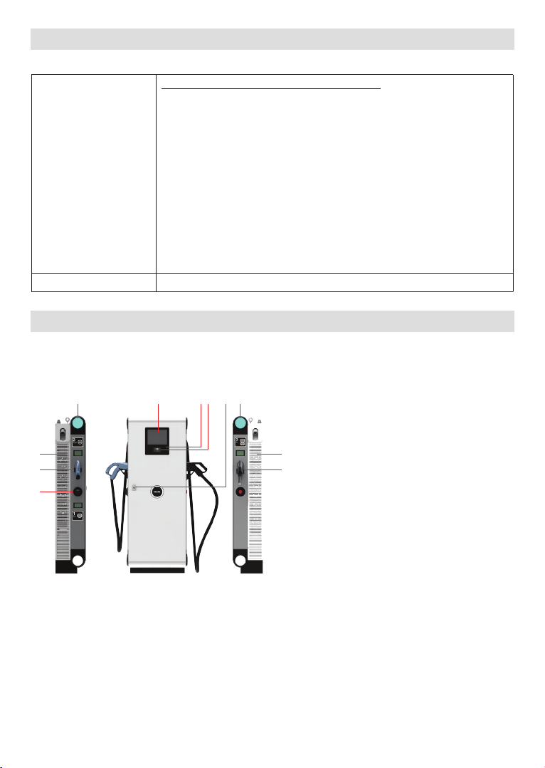
2- DESCRIPTION.................................................................................................................................5
3 - GENERAL INFORMATION.............................................................................................................5
3.1 - INTRODUCTION OF THE PRODUCT COMPONENTS...................................................5
3.2 - DIMENSIONAL DRAWINGS.........................................................................................6
3.3 - ELECTRIC VEHICLE CHARGING STATION EXPLODED PICTURE...............................7
4 - REQUIRED EQUIPMENT, TOOLS and ACCESSORIES....................................................................9
4.1 - SUPPLIED INSTALLATION EQUIPMENTS and ACCESSORIES..................................9
4.2 - RECOMMENDED EQUIPMENTS and TOOLS.............................................................9
5 - ELECTRICAL SPECIFICATION.....................................................................................................10
6 - USER INTERFACE & AUTHENTICATION.....................................................................................10
7 - CONNECTIVITY.............................................................................................................................11
8 - MECHANIC SPECIFICATIONS........................................................................................................11
9 - ENVIRONMENTAL TECHNICAL SPECIFICATIONS......................................................................11
10 - INSTALLING CHARGE STATION...................................................................................................11
10.1 - UNPACK CHARGING STATION.................................................................................12
10.2 - BOX CONTENTS FOR CHARGING STATION...........................................................13
10.3 - FOUNDATION, ALINGMENT & PLACEMENT............................................................14
10.4 - OPENING SIDE COVERS...........................................................................................19
10.5 - CABLE INSTALLATION............................................................................................20
10.5.1 - OPENNING SIDE COVER AND CABLE CONNECTION.........................20
10.5.2 - SIM CARD CONNECTION....................................................................23
10.5.3 - CONNECT OCPP OVER ETHERNET.....................................................23
10.5.4 - CONNECT PC TO THE SAME NETWORK WITH ETHERNET PORT....25
10.5.5 - OPEN WEB CONFIG UI WITH BROWSER.............................................26
10.5.6 - MAIN PAGE.........................................................................................27
10.5.7 - MAKE SETTINGS CHANGE IN WEB CONFIG UI................................28
10.5.7.1 - GENERAL SETTINGS.......................................................28
10.5.7.2 - OCPP SETTINGS..............................................................30
10.5.7.3 - NETWORK INTERFACES SETTINGS................................34
10.5.7.4 - OCCP CONNECTIONS SETTINGS....................................35
10.5.7.5 - SYSTEM MAINTENANCE PAGE ......................................36
10.5.8 - CLOSE COVER......................................................................................39

English - 2© 2022 ZES - All rights reservedIG v1.0.0 01.2022
1 - SAFETY INFORMATION
CAUTION
RISK OF ELECTRIC SHOCK:
CAUTION: VESTEL ELECTRIC VEHICLE CHARGER DEVICE SHALL BE MOUNTED BY A LICENSED OR
AN EXPERIENCED ELECTRICIAN AS PER ANY REGIONAL OR NATIONAL ELECTRIC REGULATIONS AND
STANDARDS IN EFFECT.
CAUTION
AC grid connection and load planning of the electric vehicle charging device
shall be reviewed and approved by authorities as specified by the regional
or national electric regulations and standards in effect. For multiple electric
vehicle charger installations the load plan shall be established accordingly. The manufacturer shall
not be held liable directly or indirectly for any reason whatsoever in the event
of damages and risks that are borne of errors due to AC grid supply connection or load planning.
IMPORTANT - Please read these instructions fully before installing or operating
1.1 - SAFETY WARNINGS
• Keep this manual in a safe place. These safety and operating instructions must be kept in a
safe place for future reference.
• Check that the voltage marked on the rating label and do not use charging station without
appropriate mains voltage.
• Do not continue to operate the unit if you are in any doubt about it working normally, or if it
is damaged in any way - switch off the mains supply circuit breakers (MCCB and RCCB) in
upstream distribution panel. Consult your local dealer.
• The ambient temperature range during charging should be between –35 °C and +50 °C (without
direct sunlight) and at a relative humidity of between 5 % and 95 %. Use the charging station
only within these specified operating parameters.
• The device location should be selected to avoid excessive heating of the charging station. High
operating temperature caused by direct sunlight or heating sources, may cause reduction of
charging current or temporary interruption of charging process.
• The charging station is intended for outdoor and indoor use. It can also be used in public places.
• To reduce the risk of fire, electric shock or product damage, do not expose this unit to severe
rain, snow, electrical storm or other severe weathers. Moreover, the charging station shall
not be exposed to spilled or splashed liquids.
• Do not touch end terminals, electric vehicle connector and other hazardous live parts of the
charging station with sharp metallic objects.
• Avoid exposure to heat sources and place the unit away from flammable, explosive, harsh, or
combustible materials, chemicals, or vapors.
• Risk of Explosion. This equipment has internal arcing or sparking parts which should not be
exposed to flammable vapors. It should not be located in a recessed area or below floor level.
• This device is intended only for charging vehicles not requiring ventilation during charging.
• To prevent risk of explosion and electric shock, ensure that the specified Circuit Breaker and
RCD are connected to building grid.

English - 3IG v1.0.0 01.2022 © 2022 ZES - All rights reserved
• Charging Station bottom must be at (or above) the ground level.
• Adaptors or conversion adapters are not allowed to be used. Cable extension sets are not
allowed to be used.
• The allowed current value of the service socket is maximum 10A.
WARNING: Never let people (including children) with reduced physical, sensory or men-
tal capabilities or lack of experience and or knowledge use electrical devices unsupervised.
CAUTION: This vehicle charger unit is intended only for charging electric vehicles not
requiring ventilation during charging.
1.2 - GROUND CONNECTION WARNINGS
• Charging station must be connected to a centrally grounded system. The ground conductor
entering the charging station must be connected to the equipment grounding lug inside the
charger. This should be run with circuit conductors and connected to the equipment grounding
bar or lead on the charging station. Connections to the charging station are the responsibility
of the installer and purchaser.
• To reduce the risk of electrical shock, connect only to properly grounded outlets.
• WARNING : Make sure that during installing and using, the charging station is constantly
and properly grounded.
1.3 - POWER CABLES, PLUGS and CHARGING CABLE WARNINGS
• Be sure that plugs and sockets are compatible on charging station side.
• A damaged charging cable can cause fire or give you an electric shock. Do not use this product
if the flexible Charging cable or vehicle cable is frayed, has broken insulation, or shows any
other signs of damage.
• Ensure that the charge cable is well positioned thus; it will not be stepped on, tripped over,
or subjected to damage or stress.
• Do not forcefully pull the charge cable or damage it with sharp objects.
• Never touch the power cable/plug or vehicle cable with wet hands as this could cause a short
circuit or electric shock.
• To avoid a risk of fire or electric shock, do not use this device with an extension cable. If the
mains cable or vehicle cable is damaged it must be replaced by the manufacturer, its service
agent, or similarly qualified persons in order to avoid a hazard.
• Use appropriate protection when connecting to the main power distribution cable.

English - 4© 2022 ZES - All rights reservedIG v1.0.0 01.2022
1.4 - REQUIRED UPSTREAM PROTECTIONS
• Class-I/B Lightning Protection must be connected to the upstream distribution panel. Min.
cable length between the charger and the protection device recommended to be 10m. *The
charger contains Class II/C Type Surge Protector Device (SPD) – Phoenix, VAL-MS230/3+1 FM
• MCCB (Thermic Magnetic Adjustable) must be connected to the upstream distribution box.
Model
CCS
CHADEMO
AC Socket
Power Out
Input Max
AC current
Recommended Cross
Section for
L1-L2-L3 (mm2)
Recommended Cross
Section for Neutral
Recommended Cross
Section
for PE (mm2)
Required Circuit
Breaker
EVC06- DC-
60CHS 30 30 22 60kW+22kW 151A 70 16 70 200 A
TMF
EVC06-
DC60CCS 30 30 22 60kW+22kW 151A 70 16 70 200 A
TMF
EVC06- DC-
60CS 60 - 22 60kW+22kW 151A 70 16 70 200 A
TMF
EVC06-
DC60C 60 - - 60kW 151A 70 16 70 200 A
TMF

English - 5IG v1.0.0 01.2022 © 2022 ZES - All rights reserved
2- DESCRIPTION
Model Name
EVC06-DC Series (Name Coding: EVC06-DC****)
1st Asterisk (*) : Rated Power
60 : 60 kW DC Power Output
2nd Asterisk (*) : DC output combination 1
C : CCS Output
3rd Asterisk (*) : DC output combination 2
C : CCS Output
H : CHAdeMO Output
4th Asterisk (*) : AC output combination
Blank : No AC Output
S : AC22 kW Socket Output
Cabinet EVC06
3 - GENERAL INFORMATION
3.1 - INTRODUCTION OF THE PRODUCT COMPONENTS
2 3 94 1
5
8
10
6
7
1
All images are given for the full version of the product.
1-Led Indicator
2 - Display
3-RFID Reader
4-ALS Sensor
5-DC CCS Output Outlet
6-DC CHAdeMO Outlet
7-AC 22kW Socket Outlet
8-Access Cover For Fan
9-Access Cover for CTB, PLC Board
and HMI
10 - Access Cover for Power Modules

English - 6© 2022 ZES - All rights reservedIG v1.0.0 01.2022
3.2 - DIMENSIONAL DRAWINGS
Front, Side and Top View
Figure.2

English - 7IG v1.0.0 01.2022 © 2022 ZES - All rights reserved
3.3 - ELECTRIC VEHICLE CHARGING STATION EXPLODED PICTURE
Figure-3

English - 8© 2022 ZES - All rights reservedIG v1.0.0 01.2022
NO PART DESCRIPTION NU NO PART DESCRIPTION NU
1 MAIN BODY 1 19 COSMETIC SIDE COVER 4
2 METAL MODUL BOTTOM 1 20 CABLE GLAND M32 5
3 SUPPORT METAL MODUL 8 21 METAL COVER LEFT 1
4 METAL MODUL TOP 1 22 FRAME FILTER LEFT 1
5 MOUNTING PLATE 1 23 CABLE COVER 2
6 FUSE METAL SUPPORT 1 24 SIDE FILTER COVER 2
7 CABLE COVER 1 25 METAL COVER RIGHT 1
8 METAL BRACKET PSU 1 26 FRAME FILTER RIGHT EVC06 1
9 METAL BRACKET KLEFER 1 27 AIR FILTER C G4 1050X150 2
10 METAL BRACKET N-PE 1 28 INNER GRILL EVC06 2
11 METAL BRACKET U-SWITCH 1 29 MOUNTING PLATE TOP 1
12 CABLE GLAND M20 3 30 COVER PLATE TOP 1
13 HINGE 3 31 COVER PLATE BOTTOM 1
14 EMERGENCY BUTTON COVER 1 32 BOTTOM COVER METAL 1
15 SEAL FOAM EMERGENCY 1 33 COVER BOTTOM COVER 2
16 SEAL FOAM COSMETIC SIDE COVER 4 34 DIFFUSER PLATE 4
17 COSMETIC BOTTOM COVER AL 1 35 FRONT COVER EVC06 1
18 COSMETIC TOP COVER AL 1

English - 9IG v1.0.0 01.2022 © 2022 ZES - All rights reserved
4 - REQUIRED EQUIPMENT, TOOLS and ACCESSORIES
4.1 - SUPPLIED INSTALLATION EQUIPMENTS and ACCESSORIES
M20 Steel Expansion Bolt x4
Special Spanner M50 x M40
Flange M12 Bolts x4
1 set (x2) Lock Keys
RJ45 Male Connector
4.2 - RECOMMENDED EQUIPMENTS and TOOLS
Ø20 Drill Bit Impact Drill PC
Philips Screwdriver RJ45 Crimping Tool Cat5e or cat6 ethernet cable
13(M8) , 17(M10),
19(M12) Spanner Hammer

English - 10© 2022 ZES - All rights reservedIG v1.0.0 01.2022
5 - ELECTRICAL SPECIFICATION
Model EVC06-DC Series
IEC Protection class Class - I
IEC EMC Class IEC 61000-6-3 Class B-Residential(Emission)
IEC 61000-6-2 Industrial(Immunity)
Power Input
Input Rating 400 Vac ±10% , 50/60 Hz, 190 A / phase
Connection 3P - N – PE(TNS,TNC-S,TT)
Power Factor > 0.98
Efficiency > % 95
CCS Output
Max Power 60 kW
Voltage Range 200 – 920 Vdc (Single CCS Outlet Models)
200 - 500 Vdc (Dual DC Outlet Models)
Maximum Current 125 A
Interface Compliance
IEC62196-1 / 3
IEC 61851-1 / 23 / 24
ISO 15118-1 / 2 / 3
DIN 70121
CCS - 2
Output
Max Power 60 kW
Voltage Range 200 - 500 Vdc
Maximum Current 125 A
Interface Compliance
IEC62196-1 / 3
IEC 61851-1 / 23 / 24
ISO 15118-1 / 2 / 3
DIN 70121
CHAdeMO
Output
Max Power 60 kW
Voltage Range 150 – 500 Vdc
Maximum Current 125 A
Interface Compliance
IEC62196-1 / 3
IEC 61851-1 / 23 / 24
CHAdeMO Rev. 2.0
Type-2 Socket
Outlet
Max Power 22 kW (400Vac 50/60 Hz)
Voltage Range 32 A / phase
Interface Compliance IEC62196-1/2 IEC61851-1
Internal Protections
Residual current sensing, Insulation monitoring, Over
current / Over voltage / Under voltage / Short circuit /
Over Temperature / Surge Protection

English - 11IG v1.0.0 01.2022 © 2022 ZES - All rights reserved
6 - USER INTERFACE & AUTHENTICATION
Display 10.4” Color TFT LCD
User Interface High Brightness Resistive Touch Screen
RFID Reader Module ISO/IEC14443A/B and ISO/IEC-15693
Payment module (Optional) Contactless Credit card kit options
AC+DC MID Meter(Optional) MID meter Certified
AC+DC MID Meter(Optional) Eichrecht conformity for Germany
7 - CONNECTIVITY
LAN Connectivity Ethernet
WLAN Connectivity 2.4GHz: 802.11 b/g/n
5GHz: 802.11 a/n/ac
Mobile Connectivity GSM 900/1800 UMTS 900/2100
LTE Band 1/3/7/8/20/28A
OCPP Specification OCPP 1.6 J
8 - MECHANIC SPECIFICATIONS
Material Metal Panel
Protection Degree Ingress Protection
Impact Protection
IP54
IK10
Cooling Forced Air Cooling Fan
Cable Length CCS: 3.50 m
CHAdeMO: 3.50 m
Dimensions (Product) 1750 mm (Height) x 650 mm (Width) x 350 mm (Depth)
Dimensions (with packing) 1900 mm (Height) x 550 mm (Width) x 900 mm (Depth)
Weight (Product) 210 kg.
Weight with Package 310 kg with packing
9 - ENVIRONMENTAL TECHNICAL SPECIFICATIONS
Operation Condition Temperature
Humidity
Altitude
-35°C to + 50 °C (Derating is applied over + 45 °C)
5 % - 95 % (Relative humidity, non-condensing)
0 - 2,000m

English - 12© 2022 ZES - All rights reservedIG v1.0.0 01.2022
10 - INSTALLING CHARGE STATION
Screws inside the product are recommended to be exceeding 240 hours Salt Fog test under ASTM
B117 Method. Screws outside the product are recommended to be exceeding 720 hours.
WARNING: RISK OF ELECTRICAL SHOCK AND INJURY. POWER OFF THE CHARGING STATION MAIN
SUPPLY BEFORE ANY INSTALLATION STEPS
WARNING: TO AVOID PERSONAL INJURY OR DAMAGE THE CHARGING STATION, ENSURE THE
INSTALLATION AREA IS SUITABLE AND THE FLOOR CAN WITHSTAND THE WEIGHT OF THE CHARGING
STATION.

English - 13IG v1.0.0 01.2022 © 2022 ZES - All rights reserved
10.1 - UNPACK CHARGING STATION
Unpack the charging station as shown in figure below.
Note that, front and top covers are marked as shown in the figures.
Figure.4

English - 14© 2022 ZES - All rights reservedIG v1.0.0 01.2022
10.2 - BOX CONTENTS FOR CHARGING STATION
User Manual and Installation Guideline 1 Master + 2 User RFID Card
User Manual
ELECTRIC VEHICLE CHARGER
EVC06 Series
User Manual
ELECTRIC VEHICLE CHARGER
EVC06 Series
Master
User
User
Figure.5

English - 15IG v1.0.0 01.2022 © 2022 ZES - All rights reserved
10.3 - FOUNDATION, ALINGMENT & PLACEMENT
The concrete foundation dimensions are shown as below:
Figure.6
1- Dig a foundation pit in the ground according to the dimensions of the concrete foundation
shown at Figure.
2- Make the rectangular hole for cables which come from main supply (3P+N+PE and Commu-
nication) on the concrete foundation from top to bottom. The dimensions and the position on the
concrete foundation are shown at Figure.
3- Make the cable duct on the concrete foundation. There are 4 cable duct options according to
the direction from main supply. The cable duct can be at one of the right(A), left(C), front(B) and
back(D) side of the concrete foundation. For these 4 options; The position and diameter of the
cable duct are shown at Figure.
4- The top surface of the foundation must be at least 20 mm above the ground.

English - 16© 2022 ZES - All rights reservedIG v1.0.0 01.2022
FRONT BACK VIEW
20mm
400mm
300mm
170mm
Ø120mm
A,C
LEFT RIGHT VIEW
20mm
400mm
245mm
170mm
Ø120mm
B,D
Figure.7( All options of cable ducts A,B,C and D are shown )
5- Open the right side cover of the product using the keys provided by turning the handle
counterclockwise with wide angle.
6- The cable length of 80 cm should be available above the foundation for cable assembly in cabinet.
7- Drill 4 holes on the concrete foundation with dimensions shown at Figure and tap M20x170
mm expansion bolt in these holes stated as shown at Figure.

English - 17IG v1.0.0 01.2022 © 2022 ZES - All rights reserved
8- Remove the (left and right) bottom side plates by unscrewing the plates.
Figure.8

English - 18© 2022 ZES - All rights reservedIG v1.0.0 01.2022
9- Lift the charging station by lifting eyebolts and place the station on the concrete foundation
such that the base holes of the charger are aligned with these expansion bolts in figure. Tighten
the expansion bolts with nuts. The type of expansion bolts used are shown at Figure.
A
800mm
577mm
514mm A
A
A
Figure.6
Holes Drill Diameter : Ø20 mm, Drill Depth : 155 mm (Torque: 480Nm)
Figure.9
Figure.10
RIGHT VIEWFRONT VIEW

English - 19IG v1.0.0 01.2022 © 2022 ZES - All rights reserved
10- Remove the eyebolts after placement of the charging station. Plug the bolts with the washers.
Figure.11
You can continue following “Cable Installation” steps.
This manual suits for next models
4
Table of contents
Popular Batteries Charger manuals by other brands

NOCO Genius
NOCO Genius G26000EU User guide & warranty

GYS
GYS NOMAD POWER 15 AIR manual

Everpower Electronics
Everpower Electronics EP12M248 user manual

Twisty Ride
Twisty Ride MOTORCYCLE & SCOOTER IPHONE 5 CHARGER user manual

Narada
Narada 313K Series Operation manual

Webasto
Webasto DVS100 installation manual