Everpower Electronics EP12M248 User manual
1
http://www.oceanpowercharger.com
7 Stage Automatic Smart Battery Charger
Desulphuration& Maintainer
(FOR CHARGING 12V / 24V AGM, GEL,SLA AND WET BATTERIES)
USER MANUAL
THIS MANUAL CONTAINS IMPORTANT
SAFETY AND OPERATING INSTRUCTIONS

2
http://www.oceanpowercharger.com
IMPORTANT SAFETY INSTRUCTIONS
Please read this manual and follow the instructions carefully
before using the charger
.
WARNING
The EP12M248 charger is designed to charge 12V lead-acid
batteries from 6Ah to 160Ah and maintain batteries up to 200Ah.
The EP24M124 charger is designed to charge 24Vlead-acid
batteries from 4Ah to 80Ah and maintain batteries up to 100Ah.
Check battery manufacturer specifications before using this charger.
Explosive gases may escape from the battery during charging.
Provide ventilation to prevent flames and sparks.
Do not expose charger to rain, snow or liquids.
Battery acid is corrosive. Rinse immediately with water if acid comes
into contact with skin or eyes.
Do not charge a frozen or damaged battery.
Do not charge non-rechargeable batteries.
Do not place the charger on the battery while charging.
Be extra cautious to reduce risk of dropping a metal tool onto
battery. It might spark or short-circuit battery or other electrical part
that may cause explosion.
When working with a lead-acid battery, remove personal metal items
such as rings, bracelets, necklaces, watch…
Do not smoke or allow a spark or flame while charging.
In order to reduce risk of electric shock, unplug charger from AC
outlet before doing any maintenance or cleaning.
Not for use by children or by anyone who is unable to follow
instructions of this manual, unless they are supervised by an adult
to ensure the proper use of charger.
MAIN FEATURES:
High efficiency (>85%).
Selectable charging rates to suit battery capacity.
Selectable battery type.
Temperature self-compensation: Charging voltage adapts to
temperature to prevent over or under battery charging.
Capable of recharging severely discharged or heavily sulfated
battery.
Reverse polarity protection, short circuit protection, sparks free
contact.
Ultra low input power consumption while in standby mode.
Ease of use. Clear charging status display.
Full microprocessor controlled.
Does not over chargeyour battery even if it is kept connected in
maintenance float mode.
Multi Charge Stages:
oBattery desulphation charging
oSoft start charging
oBulk charging
oAbsorption charging
oBattery analysis
oRecondition charging
oFloat & maintenance charging
3
http://www.oceanpowercharger.com
Temperature sensor
Temperature & Safety Protection:
INTERNAL OVERHEAT PROTECTION: The charger is equipped
with built-in overheat and overload electronic circuit protection
TIMER PROTECTION: Charger provides the maximum charging
time for each charging stage. In the event it is wired to recharge a
larger than recommended battery, charger will stop charging after
maximum stage recommended time and the RED LED will be FLASH
slowly. At this point, Battery must be disconnected.
REVERSE POLARITY: Charger has reverse battery protection. (Red
LED ON, while output leads are connected backwards), Disconnect
and correct connection to battery.
SHORT CIRCUIT PROTECTION: Charger will turn off upon
detecting a short circuit (Red LED ON.
RECOMMENDED SETTINGS:
Charge Rate:
Charge Current
1A
2A
4A
8A
Battery Capacity:
Charging (AH)
4--20
6--40
10--80
40--160
Battery Capacity:
Maintaining (AH)
4--30
6--60
10--100
40--200
Battery type:
Battery type
(Voltage value at 25℃)
Absorption
Voltage
Float
Voltage
MAX

4
http://www.oceanpowercharger.com
GEL
For Charging GEL batteries
14.1V
13.4V
14.4V
WET
For Charging FLOODED or
WET Batteries
14.4V
13.5V
14.7V
AGM
For Charging AGM, Sealed,
VRLA, Calcium batteries
14.7V
13.6V
15V
TECHNICAL SPECIFICATIONS:
ELECTRICAL PARTS:
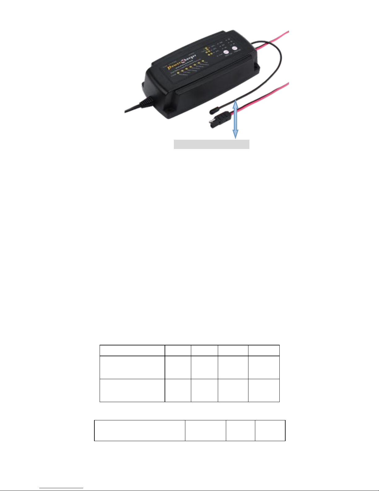
AC power cord: 6 feet SPT-2 with UL plug or VVT EU plug
Output lead: 6 feet SPT-1 2X18AWG with insulated battery clamps.
ENVIRONMENTAL CHARACTERISTICS:
Operating temperature range: 32 to 104° F
Storage temperature range: 10 to 170°F
Operating humidity range: 90% RH Max
Model
EP12M248
EP24M124
Type
Smart &
Automatic
Smart &Automatic
Input (UL Version)
115Va c
50/60Hz
115Va c
50/60Hz
Input (CE Version)
220--240Vac
50/60Hz
220--240Vac
50/60Hz
Output Voltage
12V
24V
Output Current
2/ 4 / 8A
1/ 2/ 4A
Output Volt No Load
<0.5V
<0.8V
Minimum Start Volt
>2.0V
>4.0V
Input Power
W / Load
34-126W
34-126W
Input Power
No Load
0.3-0.8W
0.8W
Temperature Compensated
-30mV/ ℃
-60mV/ ℃
Size (L*W*H)
8*3.5*2(in)
8*3.5*2(in)
Net Weight
1.87LB
1.87LB
Approval
FCC & CE
FCC & CE

5
http://www.oceanpowercharger.com
ECO MODE:
If AC power is connected, and the battery is not connected, the charger
will automatically go into ECO mode. Input power draw in ECO mode is
less than 1.5W (0.04kWh per day).
Power consumption in maintenance mode is 0.05kWh per day.
CHARGING INSTRUCTIONS:
STEP 1 - Pre Charge:
Battery & Electrolyte Level Check
Check the battery electrolyte level (Only for Flooded or WET
battery).
If necessary, remove the vent caps and add distilled water so the
levels are halfway between the upper and lower fill lines.
Check the battery label if it is 12V battery or 24V batteries etc.
STEP 2 - Connect Charger to Battery
If the battery is out of the vehicle:
Connect the Red lead from the charger to the positive (+) battery
terminal.
Connect the Black lead from the charger to the negative (-) battery
terminal.
If battery is still in the vehicle, determine if the vehicle is positively
or negatively earthed.
If Negatively earthed (Most Common) – First connect the Red (+)
battery charger lead to the Positive (+) battery post and then connect
the Black (-) battery charger lead to the vehicle’s chassis and away
from the fuel line.
If Positively earthed – First connect the Black (-) battery charger
lead to the Negative (-) battery post and then connect the Red (+)
battery charger lead to the Vehicle’s chassis and far away from the fuel
line.
STEP 3 – Connect Charger to Power (115Vac / 230Vac)
Connect the battery charger to AC mains powered socket.
The Charger will automatically start when AC power is connected
and switched on.
(Note: If the Fault Indicator LED illuminates Red, please check your
connections as it’s likely that the Positive and Negative leads are
reversed. Refer to Trouble Shooting page for further information)
STEP 4 – Disconnect Charger from Battery
If the battery is out of the vehicle:
Switch OFF and remove the AC power socket from the outlet.
Remove the black lead and then the red lead.
Check electrolyte levels if possible.
(As they may need topping up with distilled water after charging)
If the battery is in the vehicle:
Switch OFF and remove the AC power socket from the outlet.
Remove the lead from the vehicle chassis.
Remove the lead from the battery.
This manual suits for next models
1
Table of contents
Other Everpower Electronics Batteries Charger manuals


