Morningstar TrakStar TS-MPPT-60-150V User manual

Installation and Operation Manual
Solar System Controller
8 Pheasant Run
Newtown, PA 18940 USA
email: info@morningstarcorp.com
www.morningstarcorp.com
Solar Battery Charger
with
TrakStarTM Maximum Power Point Tracking Technology
Models
TS-MPPT-60-150V
TS-MPPT-45-150V
MAXIMUM POWER POINT TRACKING
TRISTAR MPPT
TM
TSMPPT.indd 1TSMPPT.indd 1 09/11/2009 12:11 PM09/11/2009 12:11 PM

Dimensions in Inches [Millimeters]
TSMPPT.indd 2TSMPPT.indd 2 09/11/2009 12:11 PM09/11/2009 12:11 PM

Contents
1.0 Important Safety Information 4
2.0 Getting Started 6
2.1 Overview 6
2.2 Versions and Ratings 6
2.3 Features 7
2.4 Regulatory Information 9
2.5 Optional Accessories 10
3.0 Installation 11
3.1 General Information 11
3.2 Controller Installation 12
4.0 Operation 24
4.1 TrakStarTM MPPT Technology 24
4.2 Battery Charging Information 26
4.3 Push button 33
4.4 LED Indications 34
4.5 Protections, Faults & Alarms 36
4.6 Inspection and Maintenance 38
5.0 Networking and Communication 39
5.1 Introduction 39
5.2 Morningstar MeterBusTM 40
5.3 Serial RS-232 41
5.4 EIA-485 (formerly RS-485) 43
5.5 Ethernet 44
6.0 Troubleshooting 47
7.0 Warranty 49
8.0 Specifications 50
TSMPPT.indd 3TSMPPT.indd 3 09/11/2009 12:11 PM09/11/2009 12:11 PM

4Important Safety Information
Save These Instructions
This manual contains important safety, installation and operating instructions for the
TriStar MPPT solar controller.
The following symbols are used throughout this manual to indicate potentially dangerous condi-
tions or mark important safety instructions:
WARNING:
Indicates a potentially dangerous condition. Use extreme caution when performing
this task.
!CAUTION:
Indicates a critical procedure for safe and proper operation of the controller.
NOTE:
Indicates a procedure or function that is important for the safe and proper operation
of the controller.
Safety Information
Read all of the instructions and cautions in the manual before beginning installation.•
There are no user serviceable parts inside the TriStar MPPT. Do not disassemble or at-•
tempt to repair the controller.
Disconnect all sources of power to the controller before installing or adjusting the•
TriStar MPPT.
There are no fuses or disconnects inside the TriStar MPPT. Do not attempt to repair.•
Install external fuses/breakers as required.•
1.0 Important Safety Information
TSMPPT.indd 4TSMPPT.indd 4 09/11/2009 12:11 PM09/11/2009 12:11 PM

5TriStar MPPT Operator’s Manual
Installation Safety Precautions
WARNING:
This unit is not provided with a GFDI device. This charge controller must be used with an
external GFDI device as required by the Article 690 of the National Electrical Code for
the installation location.
Mount the TriStar MPPT indoors. Prevent exposure to the elements and do not allow wa-•
ter to enter the controller.
Use insulated tools when working with batteries.•
Avoid wearing jewelry during installation.•
The battery bank must be comprised of batteries of same type, make, and age.•
Do not smoke in the vicinity of the battery bank.•
Power connections must remain tight to avoid excessive heating from a loose connection.•
Use properly sized conductors and circuit interrupters.•
The grounding terminal is located in the wiring compartment and is identified by the sym-•
bol below.
Ground Symbol
This charge controller is to be connected to DC circuits only. These DC connections are•
identified by the symbol below.
Direct Current Symbol
About this Manual
This manual provides detailed installation and usage instructions for the TriStar MPPT controller.
Only qualified electricians and technicians who are familiar with solar system design and wiring
practices should install the TriStar MPPT. The usage information in this manual is intended for
the system owner/operator.
TSMPPT.indd 5TSMPPT.indd 5 09/11/2009 12:11 PM09/11/2009 12:11 PM

6TriStar MPPT Operator’s Manual
Getting Started2.0
2.1 Overview
Thank you for selecting the TriStar MPPT solar charge controller with TrakStarTM MPPT Technol-
ogy. The TriStar MPPT (TS-MPPT) is an advanced maximum power point tracking solar battery
charger. The controller features a smart tracking algorithm that finds and maintains operation at
the solar array peak power point, maximizing energy harvest.
The TriStar MPPT battery charging process has been optimized for long battery life and im-
proved system performance. Self-diagnostics and electronic error protections prevent damage
when installation mistakes or system faults occur. The controller also features eight (8) adjustable
settings switches, several communication ports, and terminals for remote battery temperature
and voltage measurement.
Please take the time to read this operator’s manual and become familiar with the controller. This
will help you make full use of the many advantages the TriStar MPPT can provide for your PV
system.
2.2 Versions and Ratings
There are two versions of TriStar MPPT controllers.
TriStar-MPPT-45-150V
maximum 45 amps continuous battery current•
12, 24, 36, and 48 Volt dc systems•
maximum 150 Volt dc solar input voltage•
RS-232 and MeterBus• TM communication ports
TriStar-MPPT-60-150V
maximum 60 amps continuous battery current•
112, 24, 36, and 48 Volt dc systems•
maximum 150 Volt dc solar input voltage•
RS-232, EIA-485, MeterBus• TM, and Ethernet communication ports
To comply with the National Electric Code (NEC), the current rating of the controller must be
equal to or greater than 125% of the solar array’s short circuit current output (Isc). Therefore, the
maximum allowable solar array input to the TriStar MPPT controller for compliance with the NEC
is:
TS-MPPT-45: 36 amps Isc*
TS-MPPT-60: 48 amps Isc*
*Solar array Isc @ STC
TSMPPT.indd 6TSMPPT.indd 6 09/11/2009 12:11 PM09/11/2009 12:11 PM

7TriStar MPPT Operator’s Manual
2.3 Features
The features of the TriStar MPPT are shown in Figure 2-1 below. An explanation of each feature
is provided.
Figure 2-1. TriStar MPPT features
TSMPPT.indd 7TSMPPT.indd 7 09/11/2009 12:11 PM09/11/2009 12:11 PM

8Getting Started
1 - Heatsink
Aluminum heatsink to dissipate controller heat
2 - Mounting Hanger
Keyhole slot for mounting
3 - Settings Switches
Eight (8) settings switches to configure operation of the TriStar MPPT
4 - Battery Positive Terminal (red)
Power connection for Battery (+)
5 - Remote Temperature Sensor Terminals
Connection point for a Morningstar RTS (optional) to remotely monitor battery temperature
6 - LED Indicators
Three state of charge (SOC) LED indicators show charging status and controller faults
7 - MeterBusTM Port
RJ-11 socket for Morningstar MeterBusTM network connections
8 - Battery Voltage Sense Terminals
Terminals for battery voltage input provide accurate battery voltage measurement
9 - Ground Terminal
A chassis ground terminal for system grounding
10 - Ethernet Port
RJ-45 socket for LAN/internet connections (TS-MPPT-60-150V model only)
11 - Wiring Box with Conduit Knockouts
Termination points for wiring conduit and wire glands
12 - Wiring Box Cover
Sheet metal wiring box cover protects power connections
13 - Serial RS-232 Port
9-pin serial connector (female)
14 - EIA-485 Port
Four (4) position screw terminal for EIA-485 bus connections (TS-MPPT-60-150V model only)
15 - Solar Positive Terminal (yellow)
Power connection for Solar (+)
16 - Common Negative Power Terminals
Two (2) negative terminals for negative system cable termination
17 - Push-button Switch
Manually reset from an error or fault, also used to start/stop a manual equalization.
TSMPPT.indd 8TSMPPT.indd 8 09/11/2009 12:11 PM09/11/2009 12:11 PM

9TriStar MPPT Operator’s Manual
2.4 Regulatory Information
NOTE:
This section contains important information for safety and
regulatory requirements.
The TriStar MPPT controller should be installed by a qualified technician according to the electri-
cal rules of the country in which the product will be installed.
TriStar MPPT controllers comply with the following EMC standards:
• Immunity: EN61000-6-2:1999
• Emissions: EN55022:1994 with A1 and A3 Class B1
• Safety: EN60335-1 and EN60335-2-29 (battery chargers)
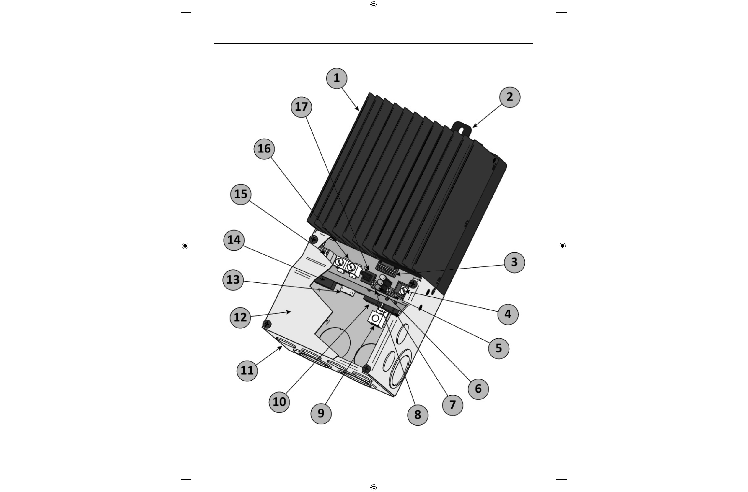
A means shall be provided to ensure all pole disconnection from the power supply. This discon-
nection shall be incorporated in the fixed wiring.
Using the TriStar MPPT grounding terminal (in the wiring compartment), a permanent and reli-
able means for grounding shall be provided. The clamping of the earthing shall be secured
against accidental loosening.
The entry openings to the TriStar MPPT wiring compartment shall be protected with conduit or
with a bushing.
FCC requirements:
This device complies with Part 15 of the FCC rules. Operation is subject to the following two conditions: (1) This
device may not cause harmful interference, and (2) this device must accept any interference received, including
interference that may cause undesired operation.
Changes or modifications not expressly approved by Morningstar for compliance could void the user’s authority to
operate the equipment.
Note:
This equipment has been tested and found to comply with the limits for a Class B digital device, pursuant to Part 15
of the FCC rules. These limits are designed to provide reasonable protection against harmful interference in a resi-
dential installation. This equipment generates, uses, and can radiate radio frequency energy and, if not installed and
used in accordance with the instruction manual, may cause harmful interference to radio communication. However,
there is no guarantee that interference will not occur in a particular installation. If this equipment does cause harmful
interference to radio or television reception, which can be determined by turning the equipment on and off, the user
is encouraged to try to correct the interference by one or more of the following measures:
Reorient or relocate the receiving antenna.•
Increase the separation between the equipment and receiver.•
Connect the equipment into an outlet on a circuit different from that to which the receiver is connected.•
Consult the dealer or an experienced radio/TV technician for help.•
This Class B digital apparatus complies with Canadian ICES-003.
Cet appareil numerique de la classe B est conforme a la norme NMB-003 du Canada.
TSMPPT.indd 9TSMPPT.indd 9 09/11/2009 12:11 PM09/11/2009 12:11 PM

10 Getting Started
2.5 Optional Accessories
The following accessories are available for purchase separately from your authorized Morning-
star dealer.
TriStar Digital Meter 2 / TriStar Remote Meter 2 (Models: TS-M-2 / TS-RM-2)
The TriStar Digital Meter mounts directly on the TS-MPPT controller, replacing the wiring box
cover. The TriStar Remote Meter can be flush mounted in a wall or into a standard duplex (2-
gang) electrical box. A 2 x 16 character display shows system operating information, error indica-
tions, and self-diagnostic information. Four (4) buttons make navigating the meter menus easy.
For systems where multiple TS-MPPT controllers are networked together, one (1) meter can
display full system information. The TriStar meters connect to the RJ- 11 MeterBusTM port on the
TriStar-MPPT.
Meter Hub (HUB-1)
A Morningstar MeterBusTM network with multiple controllers requires a Meter Hub for electrical
isolation. The HUB-1 allows communication between MeterBusTM compatible Morningstar prod-
ucts, including the TriStar MPPT controller. DIN rail compatible. See section 5.2 for more details.
Relay Driver (RD-1)
The Relay DriverTM accessory enables the TriStar MPPT to control external devices. Four (4)
relay control ports can be configured (in various combinations) to perform the following tasks:
generator control (2-, 3-, and 4-wire configurations)•
dry contacts for alarms and other signals•
advanced load control•
vent fan control•
DIN rail compatible or surface mount•
For more information on the Relay Driver, visit our website at www.morningstarcorp.com or in-
quire with your local Morningstar dealer.
EIA-485 / RS-232 Communications Adapter (RSC-1)
Connect one or more TriStar MPPT controllers to a PC or to other serial devices using the RSC-1
EIA-485 adapter. The adapter converts an RS-232 serial interface to EIA-485 compliant signals.
An LED shows network activity and errors. DIN rail compatible.
TSMPPT.indd 10TSMPPT.indd 10 09/11/2009 12:11 PM09/11/2009 12:11 PM

11 Installation
3.1 General Information
The mounting location is important to the performance and operating life of the controller. The
environment must be dry and protected from water ingress. If required, the controller may be in-
stalled in a ventilated enclosure with sufficient air flow. Never install the TriStar MPPT in a sealed
enclosure. The controller may be mounted in an enclosure with sealed batteries, but never
with vented/flooded batteries. Battery fumes from vented batteries will corrode and destroy the
TriStar MPPT circuits.
Multiple TriStars can be installed in parallel on the same battery bank to achieve higher charging
current. Additional parallel controllers can also be added in the future. Each TriStar MPPT must
have its own solar array.
!CAUTION: Equipment Damage or Risk of Explosion
Never install the TriStar MPPT in an enclosure with vented/flooded batteries. Battery
fumes are flammable and will corrode and destroy the TriStar MPPT circuits.
!CAUTION: Equipment Damage
When installing the TriStar MPPT in an enclosure, ensure sufficient ventilation.
Installation in a sealed enclosure will lead to over-heating and a decreased product
lifetime.
The installation is straightforward, but it is important each step is done correctly and safely. A
mistake can lead to dangerous voltage and current levels. Be sure to carefully follow each in-
struction in this section. Read all instructions first before beginning installation.
The installation instructions are for installation of a negative grounded system. National Electrical
Code (NEC) requirements are noted on occasion for convenience, however the installer should
have a complete understanding of NEC and UL requirements for photovoltaic installations.
Recommended Tools:
Wire strippers•
Wire cutters•
#2 & #0 Phillips screwdriver•
slotted screwdrivers•
Pliers•
Drill•
3/32” (2.5 mm) drill bit•
Level•
hack saw (cutting conduit)•
Installation3.0
TSMPPT.indd 11TSMPPT.indd 11 09/11/2009 12:11 PM09/11/2009 12:11 PM

12 Installation
3.2 Controller Installation
Step 1 - Remove the wiring box cover
!CAUTION: Shock Hazard
Disconnect all power sources to the controller before removing the wiring box cover. Never
remove the cover when voltage exists on any of the TriStar MPPT power connections.
Use a #2 Phillips screw driver to remove the four (4) screws that secure the wiring box cover as
shown in figure 3-1 below.
Figure 3-1. Remove the wiring box cover.
If a TriStar Digital Meter display is installed, be sure to disconnect the RJ-11 cable.
Step 2 - Remove the knockouts
Knockouts are provided for routing cables through conduit or wire glands. Table 3-1 below pro-
vides the knockout sizes and quantity on the TriStar MPPT wiring box. Knockout locations and
dimensions are on the inside front cover.
Quantity Trade Size Hole Dimension
8 1/2” or M20 7/8” (22.2 mm)
6 1 “ 1 - 23/64 “ (34.5 mm)
4 1 - 1/4 “ 1 - 23/32 “ (43.7 mm)
Table 3-1. Knockout sizes
!CAUTION: Shock Hazard
Always use bushings, connectors, clamp connectors, or wire glands in the knockout openings to
protect wiring from sharp edges.
!CAUTION: Shock Hazard
Never route network cables in the same conduit as the power conductors.
Plan the routing of each conductor that will connect to the TriStar MPPT before removing any
knockouts. The 1/2” (M20) knockouts are ideal for routing network cables, which must be placed
in separate conduit.
TSMPPT.indd 12TSMPPT.indd 12 09/11/2009 12:11 PM09/11/2009 12:11 PM

13TriStar MPPT Operator’s Manual
Step 3 - Mount to a Vertical Surface
Figure 3-2. Attaching the mounting hanger
Attach the mounting hanger to the bottom of the TriStar MPPT with the M6 screw provided as1.
shown in figure 3-2.
Place the TriStar MPPT on a vertical surface protected from direct sun, high temperatures,2.
and water. The TriStar MPPT requires at least 6” (150 mm) of clearance above and below
and at least 1” (25 mm) on each side for proper air flow as shown in figure 3-3 below.
Figure 3-3. Required mounting clearance for air flow.
Place a mark on the mounting surface at the top of the keyhole.3.
Remove the controller and drill a 3/32” (2.5 mm) hole at the drill mark.4.
Insert a #10 screw (included) into the top pilot hole. Do not tighten the screw completely.5.
TSMPPT.indd 13TSMPPT.indd 13 09/11/2009 12:11 PM09/11/2009 12:11 PM

14 Installation
Leave a 1/4” (6 mm) gap between the mounting surface and screw head.
Carefully align the keyhole on the TriStar MPPT with the screw head. Slide the TriStar MPPT6.
down over the keyhole.
Check for vertical plumb with a level.7.
Mark two (2) mounting hole locations in the wiring box.8.
Remove the controller and drill 3/32” (2.5 mm) holes at the drill marks.9.
Carefully align the keyhole on the TriStar MPPT with the screw head. Slide the TriStar MPPT10.
down over the keyhole.
The pre-drilled pilot holes should align with the mounting holes in the wiring box. Secure the11.
controller with two (2) #10 mounting screws.
Tighten the keyhole screw.12.
Step 4 - Adjust Settings Switches
Switch 1: Reserved for Future Use
Settings switch 1 should remain in the “OFF” position.
Mode Switch 1
Solar Charging OFF
future use ON
Switches 2 & 3: System Voltage
Four (4) system voltage configurations are available as shown in the table below:
System Voltage Switch 2 Switch 3
Auto OFF OFF
12 OFF ON
24 ON OFF
48 ON ON
The “auto” setting allows the TriStar MPPT to detect the system voltage automatically on start up.
The test is only performed at start up and the detected system voltage will never change during
operation.
Generally, it is best to choose a specific system voltage. The auto detect feature should only be
used in situations where the system voltage is unknown ahead of time or in systems where the
system voltage may change periodically.
TSMPPT.indd 14TSMPPT.indd 14 09/11/2009 12:11 PM09/11/2009 12:11 PM

15TriStar MPPT Operator’s Manual
Switches 4, 5, & 6: Battery Charging Settings
It is important to select the battery type that matches the system battery to ensure proper charg-
ing and long battery life. Refer to the specifications provided by the battery manufacturer and
choose a setting that best fits the recommended charging profile.
Settings
Switches
4 - 5 - 6
Battery
Type Absorp.
Stage
(Volts)
Float
Stage
(Volts)
Equalize
Stage
(Volts)
Equalize
Interval
(Days)
off-off-off 1 - Gel 14.00 13.70
off-off-on 2 - Sealed* 14.15 13.70 14.40 28
off-on-off 3 - Sealed* 14.30 13.70 14.60 28
off-on-on 4 - AGM/Flooded 14.40 13.70 15.10 28
on-off-off 5 - Flooded 14.60 13.50 15.30 28
on-off-on 6 - Flooded 14.70 13.50 15.40 28
on-on-off 7 - L-16 15.40 13.40 16.00 14
on-on-on 8 - Custom Custom Custom Custom Custom
* “Sealed” battery type includes gel and AGM batteries
All settings are for 12 Volt nominal systems. Multiply the charge voltage settings by 2 for 24 Volt
systems or by 4 for 48 Volt systems. A description of each setting is provided below. See sec-
tion 4.3 for full details on battery charging and a description of each of the settings in the battery
charging table.
Battery Type - The most common battery type associated with the specified charging settings.
Absorption Stage - This stage limits input current so that the Absorption voltage is maintained.
As the battery becomes more charged, the charging current continues to taper down until the
battery is fully charged.
Float Stage - When the battery is fully charged, the charging voltage will be reduced to the Float
voltage setting.
Equalize Stage - During an equalization cycle, the charging voltage will be held constant at the
specified voltage setting.
Equalize Interval - The number of days between equalization charges when the controller is con-
figured for automatic equalizations (settings switch 7).
Switch 7: Battery Equalization
Choose between manual and automatic battery equalization charging. In the manual equaliza-
tion setting, an equalization will only occur when manually started with the pushbutton or when
requested from the equalize menu on the TriStar meter. Automatic equalization will occur accord-
ing to the battery program specified by settings switches 4, 5, & 6 in the previous step.
In both settings (auto and manual), the pushbutton can be used to start and stop battery equal-
ization. If the selected battery charging setting does not have an equalization stage an equaliza-
tion will never occur, even if requested manually.
TSMPPT.indd 15TSMPPT.indd 15 09/11/2009 12:11 PM09/11/2009 12:11 PM

16 Installation
Equalize Switch 7
manual OFF
automatic ON
Switch 8: Ethernet Security
The Ethernet Security switch enables or disables configuration of the TriStar MPPT settings
through the Ethernet connection. When switch eight is set to disabled, write commands to the
TriStar MPPT custom memory are not allowed. This a safety feature to prevent unintended
changes to custom settings, but it is not a replacement for proper network security.
Configuration via TCP/IP Switch 8
disabled OFF
enabled ON
NOTE:
Adjustment of network settings and custom setpoints is always enabled via the RS-232 and EIA-
485 connections. The Ethernet Security switch only enables/disables remote configuration via
TCP/IP.
!CAUTION: Risk of Tampering
The Ethernet Security settings switch does not block write commands to devices bridged via EIA-
485.
Step 5 - Remote Temperature Sensor
The included Remote Temperature Sensor (RTS) is recommended for effective temperature com-
pensated charging. Connect the RTS to the 2-position terminal located between the pushbut-
ton and the LED’s (see figure 2-1). The RTS is supplied with 33 ft (10 m) of 22 AWG (0.34 mm2)
cable. There is no polarity, so either wire (+ or -) can be connected to either screw terminal. The
RTS cable may be pulled through conduit along with the power wires. Tighten the connector
screws to 5 in-lb (0.56 Nm) of torque. Separate installation instructions are provided inside the
RTS bag.
!CAUTION:
The TriStar MPPT will not temperature compensate charging parameters if the RTS is not used.
!CAUTION: Equipment Damage
Never place the temperature sensor inside a battery cell. Both the RTS and the battery will be
damaged.
NOTE:
The RTS cable may be shortened if the full length is not needed. Be sure to reinstall the ferrite
choke on the end of the RTS if a length of cable is removed. This choke ensures compliance with
electromagnetic emissions standards.
TSMPPT.indd 16TSMPPT.indd 16 09/11/2009 12:11 PM09/11/2009 12:11 PM

17TriStar MPPT Operator’s Manual
Step 6 - Grounding and Ground Fault Interruption
WARNING:
This unit is not provided with a GFDI device. This charge controller must be used with an
external GFDI device as required by the Article 690 of the National Electrical Code for
the installation location.
Use a copper wire to connect the grounding terminal in the wiring box to earth ground. The
grounding terminal is identified by the ground symbol shown below that is stamped into the wiring
box just below the terminal:
Figure 3-4. Ground Symbol
Do not connect the system negative conductor to this terminal. NEC requires the use of an exter-
nal ground fault protection device (GFPD). The TriStar MPPT does not have internal ground fault
protection. The system electrical negative should be bonded through a GFPD to earth ground at
one (and only one) location. The grounding point may be located in the solar circuit or the battery
circuit.
The minimum size of the copper grounding wire:
TS-MPPT-45-150V 10 AWG (6 mm• 2)
TS-MPPT-60-150V 8 AWG (10 mm• 2)
WARNING: Risk of Fire
DO NOT bond system electrical negative to earth ground at the controller. Per NEC
requirements, system negative must be bonded to earth ground through a GFPD at only
one point.
Step 7 - Battery Voltage Sense
The voltage at the battery connection on the TriStar MPPT may differ slightly from the voltage di-
rectly at the battery bank terminals due to connection and cable resistance. The Battery Voltage
Sense connection enables the TriStar MPPT to measure the battery terminal voltage precisely
with small gauge wires that carry very little current, and thus have no voltage drop. Both battery
voltage sense wires are connected to the TriStar at the 2-position terminal located between the
pushbutton and the positive (+) terminal lug (see figure 2-1).
A battery voltage sense connection is not required to operate your TriStar MPPT controller, but it
is recommended for best performance. If a TriStar meter will be added to the controller, the bat-
tery voltage sense will ensure that the voltage and diagnostic displays are very accurate.
The voltage sense wires should be cut to length as required to connect the battery to the voltage
TSMPPT.indd 17TSMPPT.indd 17 09/11/2009 12:11 PM09/11/2009 12:11 PM

18 Installation
sense terminal. The wire size can range from 16 to 24 AWG (1.0 to 0.25 mm2). A twisted pair
cable is recommended but not required. Use UL rated 300 Volt conductors. The voltage sense
wires may be pulled through conduit with the power conductors. Tighten the connector screws to
5 in-lb (0.56 Nm) of torque.
The maximum length allowed for each battery voltage sense wire is 98 ft (30 m).
Be careful to connect the battery positive (+) terminal to the voltage sense positive (+) terminal.
No damage will occur if the polarity is reversed, but the controller cannot read a reversed sense
voltage. Connecting the voltage sense wires to the RTS terminal will cause an alarm.
If a TriStar meter is installed, check the “TriStar Settings” to confirm the Voltage Sense and the
RTS (if installed) are both present and detected by the controller. MSViewTM PC software can
also be used to confirm the voltage sense is working correctly.
Step 9 - Network Connections
Network connections allow the TriStar MPPT to communicate with other controller or computers.
A network can be as simple as one controller and one PC, or as complex as dozens of control-
lers monitored via the internet. Review section 5.0 for more information about networking and the
connection(s) required for your system.
WARNING: Shock Hazard
Never route network cables in the same conduit as the power conductors.
WARNING: Shock Hazard
Only use 300 Volt UL rated communication cable.
Connect the appropriate network cables to the TriStar MPPT at this time. Access to the network
ports is easier before the power cables are attached. The ports are located inside the conduit wir-
ing box on the lower circuit board as shown in figure 3-5.
TSMPPT.indd 18TSMPPT.indd 18 09/11/2009 12:11 PM09/11/2009 12:11 PM

19TriStar MPPT Operator’s Manual
Figure 3-5. TriStar MPPT network port locations
EIA-485 Connection
The four (4) position EIA-485 connector on the TriStar MPPT must be removed to access the
terminal screws. Remove the socket connector by firmly grasping the connector body and pulling
away from the circuit board as shown in figure 3-6.
Figure 3-6. Removing the RS-485 socket connector
RS-232 Connection
The serial RS-232 port is a standard 9-pin (DB9) female connector. A low-profile serial connector
TSMPPT.indd 19TSMPPT.indd 19 09/11/2009 12:11 PM09/11/2009 12:11 PM

20 Installation
is recommended to save room in the wiring box.
NOTE:
The RS-232 and EIA-485 ports share hardware. Both ports cannot be used simultaneously.
Ethernet Connection
The RJ-45 Ethernet jack features two (2) indicator LEDs for connection status and network traf-
fic. Use CAT-5 or CAT-5e twisted pair cable and RJ-45 plugs. If possible, pull the network cable
through conduit before crimping on the RJ-45 connectors. If using pre-assembled cables, take
care not to damage the plugs when the cables are pulled through conduit.
MeterBusTM Connection
MeterBusTM networks use standard 4-wire or 6-wire RJ-11 telephone cables. If possible, pull the
telephone cable through conduit before crimping on the RJ-11 connectors. If using pre-assem-
bled cables, take care not to damage the plugs when the cables are pulled through conduit.
TSMPPT.indd 20TSMPPT.indd 20 09/11/2009 12:11 PM09/11/2009 12:11 PM
This manual suits for next models
1
Table of contents
Other Morningstar Batteries Charger manuals