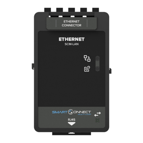
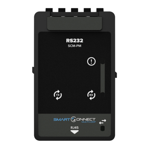
Zeta Alarm Limited SmartConnect SCM-NM User manual

DOC: GLT-294-7-13
ISS: 001
DATE: 10.02.2021
RS485 NETWORK MODULE
INSTRUCTION MANUAL
SCM-NM

2
RS485
NETWORK
MODULE INSTRUCTION MANUAL
General
The S art Connect Multi-loop syste network has the facility to onitor, indicate and control the functions of a fire
alar installation, thus allowing signals to be distributed around a large site. The network will acco odate up to
64 nodes. The network uses RS485 data co unication and a total network cable length of up to 10k is possible.
All panels will continue to function in stand-alone ode, even if the network fails. On a S art Connect Multi-loop
running in a network, all events are reported at all panels and all panels are able to re otely progra other panels
sitting on the network. Operation of outputs over the network is deter ined by the progra ed cause & effects.
Any input on the network can be progra ed to operate any output.
Installation
1. Ensure that the installation area is free fro any cables or wires that ay get caught, and that there is enough
space on the DIN rail to ount the odule. Also ensure that the DIN clip underneath the odule is in the open
position.
2. Place the odule onto the DIN rail, hooking the etal earth clip underneath onto the rail first.
3. Once the earth clip is hooked, push the botto of the odule onto the rail so that the odule sits flat.
4. Push the plastic DIN clip (located at the botto of the odule) upwards to lock and secure the odule into
position.
5. Once the odule is secured to the DIN rail, si ply connect the supplied CAT5E cable to the odule’s RJ45 port.
6. Connect the other end of CAT5E cable to the nearest unoccupied RJ45 port on the ter ination PCB.
ATTENTION: THE PANEL MUST BE POWERED DOWN AND DISCONNECTED FROM THE BATTERIES BEFORE
INSTALLING OR REMOVING ANY MODULES.

3
RS485
NETWORK
MODULE INSTRUCTION MANUAL
TRM RJ45 Port A ress Designation
Each RJ45 port on the S art Connect Multi-loop ter ination has its own unique port address. This port address is
i portant to keep note of as it is displayed on Alar /Fault essages and is used when configuring or setting up
cause and effects on the panel (See SCM operation anual GLT-261-7-11).
Securing the mo ules
The odules are designed to clip together to ake the ore secure. In addition, the S art Connect Multi-loop
panel is supplied with Din rail stoppers. These should be fitted before the first odule, and after the last odule on
each rail.
Before Powering the Panel On
1.
To prevent the risk of a spark, do not connect the batteries. Only connect the batteries after powering on the
syste fro its ain AC supply.
2.
Check that all external field wiring is clear fro any open, shorts and ground faults.
3.
Check that all the odules have been installed properly, with correct connections and place ent
4.
Check that all switches and ju per links are at their correct settings.
5.
Check that all interconnection cables are plugged in properly, and that they are secure.
6.
Check that the AC power wiring is correct.
7.
Ensure that the panel chassis has been correctly earth grounded.
Before powering on fro the ain AC supply, ake sure that the front panel door is closed

4
RS485
NETWORK
MODULE INSTRUCTION MANUAL
Power on Proce ure
1. After the above has been co pleted, turn the panel on (Via AC Only). The panel will follow the sa e power up
sequence described in initial power up section above
2. The panel will now display one of the following essages
Message
Meaning
Panel has not detected any odules fitted
during its power up check.
Power down the panel and check that the
expected odules are fitted, and that all
odule cables are correctly inserted.
Note that the panel will need at least one
odule fitted to run.
The panel has detected a new odule added
to a port that was previously e pty.
This is the usual essage seen the first ti e a
panel is configured
The panel has detected a different type of
odule fitted to a port that was previously
occupied.
The panel has detected a odule fitted to a
port that is the sa e type, but it`s serial
nu ber has changed.
This could happen if a loop odule was
swapped with another one, for exa ple.
The panel has detected no odule fitted to a
port that was previously occupied.
The panel has detected no odule changes, so
has powered up and started running

5
RS485
NETWORK
MODULE INSTRUCTION MANUAL
1.
Check that the odule configuration is as expected using the
and
to navigate the through the port
nu bers. Press the
icon to confir the changes.
2.
The new odule is now configured into the panel and is ready for use.
3.
Since the batteries are not connected, the panel will report the as re oved, lighting the yellow “Fault” LED,
inter ittently sounding the Fault buzzer, and displaying battery re oved essage on the screen.
4.
Connect the batteries, ensuring that the polarity is correct (Red wire = +ve) & (Black wire = -ve). Acknowledge
the Fault event via the display screen, and reset the panel to clear the battery fault.
5.
The panel should now re ain in the nor al condition, and you can configure the panel as nor al.
Fiel Wiring
Bus Topology
NOTE:
The terminal blocks are
removable to make wiring easier.
ATTENTION: DO NOT EXCEED POWER SUPPLY RATINGS, OR MAXIMUM CURRENT RATINGS.

6
RS485
NETWORK
MODULE INSTRUCTION MANUAL
Ring Topology
Wiring recommen ations
The S art Connect Multi-loop network can support up to 64 panels. Maxi u distance between nodes:-
*100M using standard fireproof cable
1KM using a screened data cable
*BS 5839-1:2017 requires that network cable be standard fireproof cable (enhanced fire proof cable ay be
required for specified installations).
NOTE:
It is recommended to install the network in a ring topology for protection against open
circuit and
short circuit faults.
RECOMMENDED CABLE: Belden type Screened twisted pair
NOTE: Star topology not supported

7
RS485
NETWORK
MODULE INSTRUCTION MANUAL
Front Unit LED In ications
LED Indication
Description
LED Indication
Description
Flashing yellow when a fault on the
RS485 circuit is detected.
Flashing green when the RS485 is
receiving infor ation.
Flashing green when the RS485 is
trans itting infor ation.
Pulses to show co unication
between the odule and the
otherboard.
Specifications
Specification SCM-NM
Design Standard
EN54
-
2
Approval
LPCB
(Pending)
Quiescent Current 15 A
Alar Current 17 A
Co unication Protocol
RS485 (115,200 Baud)
Maxi u Network Size
64 Nodes
Maxi u Distance Between
Nodes (for Bus or Ring*)
1KM
(using a screened data cable)
100M (using a standard fireproof cable)
Network Wiring Typologies
Bus
Ring (recommended)
Operating Te perature
-
5°C (23°F) to 40°C (104°F)
Max Hu idity
93% Non
-
Condensing
Size ( ) (HxWxD)
105 x 57 x 47
Weight
0.15KG
Reco ended Cable
Belden Screened Data Cable or Equivalent
*In a SCM Network, each network card just co unicates to its neighbours. The neighbours will then pass on the
essage if it is not intended for the , so each panel only co unicates one node length.
Table of contents
Other Zeta Alarm Limited Control Unit manuals
Popular Control Unit manuals by other brands

National Instruments
National Instruments PXIe-8245 Getting started guide

ICP DAS USA
ICP DAS USA SG-3784M user manual

Pentair
Pentair Aurora CBV-S Installation and operation manual

WEST
WEST PQP-171-P Technical documentation

Guangzhou Aosong Electronics
Guangzhou Aosong Electronics DHT11 product manual

oventrop
oventrop Regufloor H Installation and operating instructions for the specialised installer