Zetkama 221 User manual

1/12
USER MANUAL
BALANCING VALVES zSTA Fig. 221 Version: 1/2022
Date: 09.05.2022
TABLE OF CONTENTS
1. Product description
2. Requirements for maintenance staff
3. Transport and storage
4. Function
5. Application
6. Installation
7. Operation
8. Maintenance and repair
9. Valve setting
10. Causes of operating malfunctions and their elimination
11. Decommissioning
12. Warranty conditions
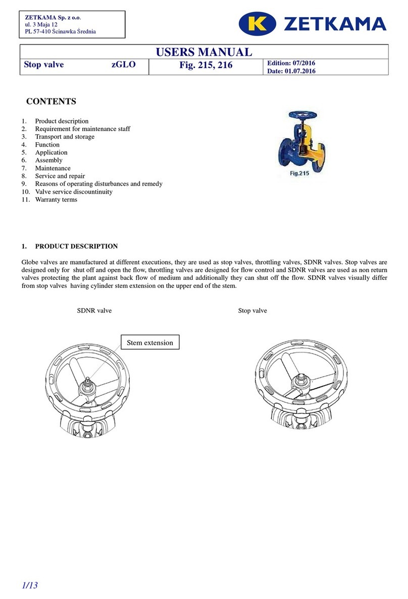
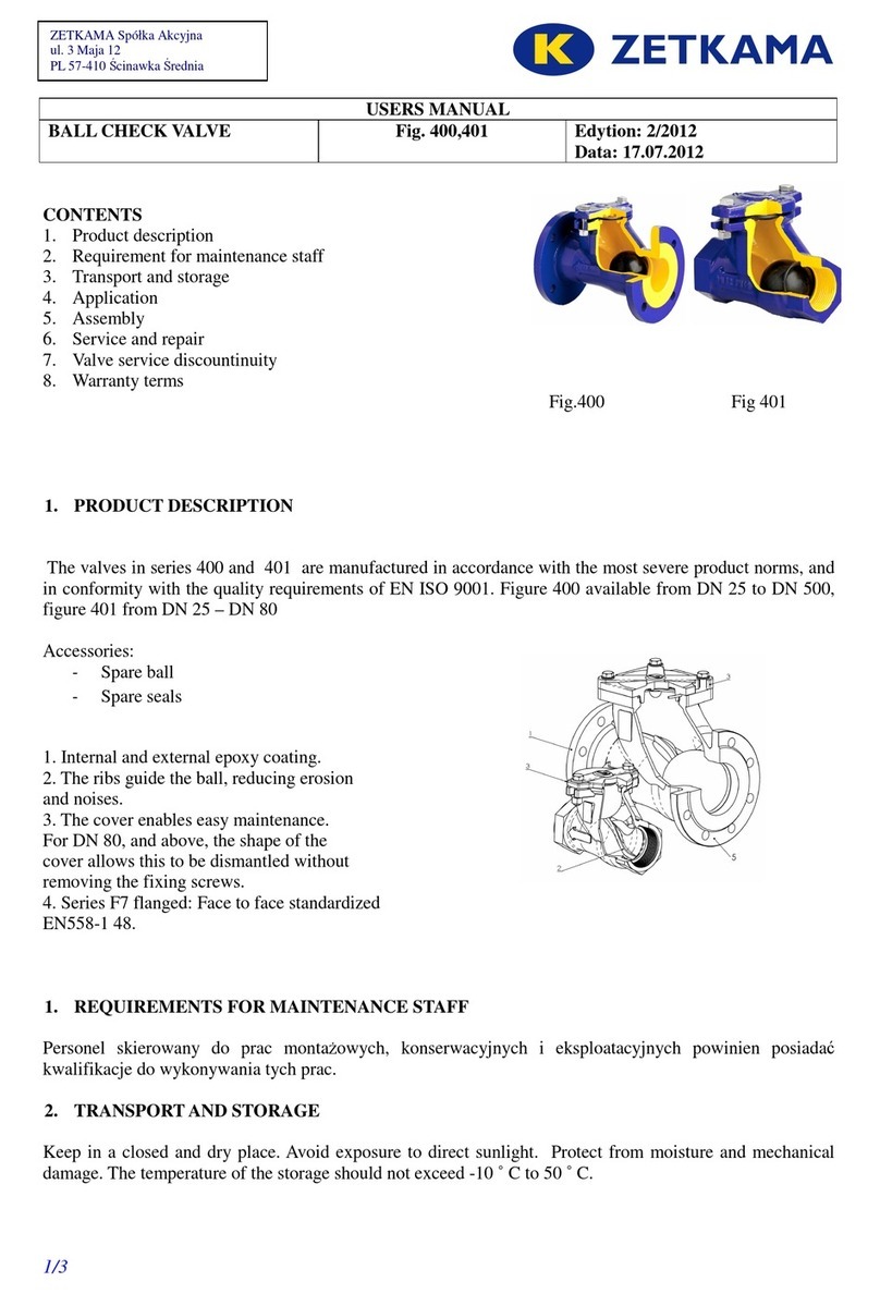
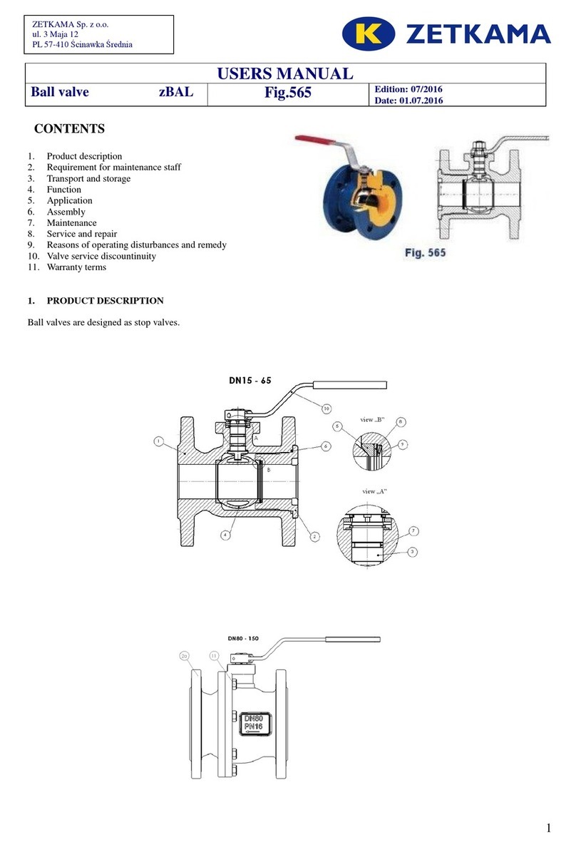
1. PRODUCT DESCRIPTION
Balancing valves Fig.221 are globe valves with threaded connections and an oblique body. They are used for
medium flow control. The medium flows in the direction indicated on the valve.
Differential pressure measurement takes place in measuring orifice. The advantage of this solution is, inter alia,
the possibility of direct flow measurement. Kv factor of the measuring orifice, where the measurement of the
differential pressure is made, is constant and does not change during flow adjustment. In practice, this means that we
can balance the system much more easily and faster. When measuring the flow rate, Kv is entered to the measuring
device only once (for the specific measuring orifice), and then the flow can easily be adjusted by observing the varying
flow on the measuring device. In this way making a flow adjustment is easy and very accurate.
H version (brass)
ZETKAMA Sp. z o.o.
ul. 3 Maja 12
PL 57-410 Ścinawka Średnia

2/12
Body material H
Type 60
1 Body CuZn36Pb2As
2 Disc CuZn36Pb2As
3 Stem CuZn36Pb2As
4 Hand-wheel Poliamid
5 Pressure tap CuZn36Pb2As + EPDM
Max. temperature 120°C
Fittings manufactured by ZETKAMA, including balance valves, have a permanent marking in accordance
with the requirements of the PN-EN19 standard. Marking facilitates technical identification and includes:
•nominal diameter DN (inch),
•nominal pressure PN (bar),
•identification of the body and cover material,
•arrow indicating the direction of flow,
•symbol of the manufacturer,
2. REQUIREMENTS FOR OPERATORS
Staff assigned to assembly, operating and maintenance should be qualified to perform this work.
During valve operation hot parts of the valve, e.g. body or cover parts could cause burn. If necessary the user should fit
insulation shields and warning signs..
3. TRANSPORT AND STORAGE
Transport and storage should be carried out at temperatures from –20
0
to 65
0
C, and the valves must be protected against
external forces. The valves must be stored in dirt-free and weather protected rooms. In humid areas drying agent or
heating should be applied to prevent formation of condensation. The valves should be transported in a manner that does
not damage the handwheel.
4. FUNCTION
Balancing valves are used to control the hydraulic system. The valves can be installed in either the supply or the
return pipelines.

3/12
5. APPLICATION
•heating
•refrigeration and air conditioning
•glycol
•industrial water
•neutral fluids
Operating medium requires or prohibits the use of certain materials. The valves are designed for normal conditions of
use. In case that operating conditions exceed these requirements, e.g. in the case of aggressive or abrasive mediums, a
user should make an inquiry to the manufacturer before ordering.
Operating pressure should be adjusted to the maximum temperature of the medium, as shown below.
Balancing valve Fig. 221 H (brass)
Acc. to EN 1092-2 Temperature [º C]
Material PN -10 to 120
CuZn36Pb2As 25 25 bar
6. INSTALLATION
The following rules must be observed during installation of balance valves:
-before installation, determine whether the valves are not damaged during shipment or storage,
make sure that the valves to be used are suitable for working conditions and media in the given plant,
-remove plugs if there are any,
-check whether the valve inside is free from foreign objects,
-for welding the valves must be protected from splashes and the used plastics from excessive heat
The pipeline to which the valves are fitted should be arranged and mounted in a way that the valve body
is not subjected to bending moment and stretching.
- use compensators in order to reduce the impact of thermal expansion of pipelines,
While installing,
pay attention to the direction of flow, indicated by an arrow on the body.
-correct operation of the valve requires suitably long straight sections: 5 x DN up and 2 x DN downstream,
-during pipeline painting valve, parts made of plastic and scale of the valve must be protected,
-valves can be mounted in any position, recommend position of the valve is wheel down,
-before starting the installation, especially after carried out repairs, rinse the pipeline through with the valve
fully open
-installation of settling tank - strainer before the valve increases certainty of its correct functioning
Use Teflon tape to seal the valves of composite material
The responsibility for correct selection of the valve to the operating conditions, distribution and
installation is borne by system designer, contractor and user.
7. OPERATION
The following rules must be observed during operation:
-start-up process – commissioning should be carried out in a way that eliminates the occurrence of sudden
changes in temperature and pressure,
-close the valve by turning it to the right, looking down on the wheel (in the direction marked on the wheel)
-open the valve by turning it to the left

4/12
the use of additional leverage when turning the wheel is prohibited
the closing cannot exceed the value of "0 -0" on the wheel
–operation of installed valves can be checked by repeated opening and closing
To ensure the safe operation of each valve, especially of the ones that are rarely used, they should be
regularly monitored. Inspection frequency should be determined by the user.
8. MAINTENANCE AND REPAIR
The balancing valves fig. 221 do not require any maintenance provided that they are used in accordance with
their intended use.
Before taking up any maintenance actions, make sure the flow of medium in the pipeline was cut off, the
pressure was reduced to ambient pressure, medium was removed and the system was cooled down.
–all maintenance and repair work should be performed by qualified personnel using suitable tools and
original spare parts.
–during maintenance and servicing use personal protective equipment appropriate to the risk involved,
–after removing the valve, replace the seals with which the valve is connected to the pipeline system,
–each time when the cover is removed, clean the valve sealing surface and apply new gasket of the same type
as previously used
–tightening the cover to the body must be made with the valve opened (disc in the upper position)
– before reassembling the valve in the pipeline it is necessary to check valve operation and tightness of all
connections. Tightness test should be carried out with water pressure of 1,5 x nominal pressure of the valve.
9. VALVE SETTING Fig. 221
The valve opening degree can be read on the dial and its lateral part
Number of turns between the closed and fully open positions is: – 4
Locking the setting
–
for the proper adjustment of valve opening tables and flow charts drawn up for each valve size should be used,
So adjusted balancing valve can be closed many times now, but its opening is only possible to the set value.

5/12
Kv values for various settings for the valve Fig. 221 version H (brass):
10. Causes of operating malfunctions and their elimination
When searching for the malfunctioning of the valve safety rules must be observed
Malfunction Possible cause Solution
No flow Valve closed Open the valve
Low flow Valve not sufficiently open Open the valve
Contaminated filter Clean or replace the strainer
Clogged pipeline system Check the pipe line
Difficult valve control Dry stem Oil the stem
Leakage on the stem Damaged o-rings Replace the o-rings
Leakage on the seat Improper closing Tighten the hand wheel without using
auxiliary tools
Damaged seat or disc Replace the valve. Contact the supplier or
manufacturer
Too high pressure difference Check that the valve is installed in
accordance with the flow direction
marked on the valve.
Medium contaminated with solid objects Clean the valve. Install a strainer upstream.
11. Decommissioning
After decommissioning and dismantling the valves must not be disposed of with household waste. Valves are made of recyclable
materials. Deliver them to a recycling centre.
DN 15 20 25 32 40 50
Type 60
Body material H
Wheel position
Valve flow Kv coefficient [m
3
/h]
0,5 1,00 2,71 2,4 4,52 5,13 7,07
1,0 1,27 3,55 3,35 6,50 7,76 9,67
1,5 1,43 3, 3,91 7,72 9,32 11,37
2,0 1,60 4,12 4,35 ,5 10,62 12,9
2,5 1,76 4,33 4, 0 9,44 12,01 14,57
3,0 2,00 4,53 5,40 10,31 13,74 16,29
3,5 2,22 4,75 6,17 11,09 15,1 1 ,26
4,0 2,34 4,94 6, 0 12,32 16,53 20,34
K
sig
2,2 7,79 11,91 21 33,66 49, 1

6/12
12. Warranty conditions
ZETKAMA grants warranty for proper operation of its products, provided that they are installed in accordance with the instruction
manual and operated in accordance with the technical specifications and parameters described in the ZETKAMA data sheets.
Warranty period is 18 months from the date of installation, but not longer than 24 months from the date of sale.
The warranty does not cover assembly of foreign parts and design changes made by the user, neither natural wear.
The user should inform ZETKAMA about hidden defects of the product immediately after detection.
Complaint must be in writing.
Address:
ZETKAMA Sp. z o.o.
ul. 3 Maja12 57-410 Ścinawka Średnia
T +48 74 865211
http:// www.zetkama.com.pl
Table of contents
Other Zetkama Control Unit manuals
Popular Control Unit manuals by other brands

Watts
Watts LFMMV Series manual

Siemens
Siemens SIRIUS ACT 3SU14 Original operating instructions

Pilz
Pilz PNOZ m0p operating instructions

Cytron Technologies
Cytron Technologies SHIELD-2AMOTOR user manual

Elnec
Elnec DIL20W/PLCC20 ZIF manual

National Instruments
National Instruments NI 9251 Getting started guide