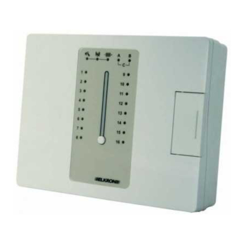
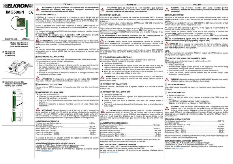
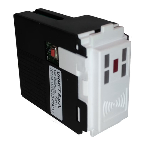
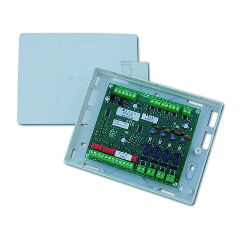
Elkron MP 110 User manual

RemoteControllable
Controlunit
DS80MP1A-005B LBT80426
MP 110
MP110TG
MP 110 M
MP110MTG

(((ELKRON)))- MP110
INDEX
1.0 System Composition ...............................................................................p. 3
1.1 MP110 Control unit....................................................................................p. 4
1.2 KP100D Remote keyboard .......................................................................p. 5
1.3 KP100 Remote keyboard ..........................................................................p. 5
1.4 DK200M Reader........................................................................................p. 5
1.5 Input/Output expansions ...........................................................................p. 5
1.6 Accessories ................................................................................................p. 6
2.0 Installation/connections ..........................................................................p. 7
2.1 MP110: Wall installation of Thermoplastic container..............................p. 7
2.2 MP110M: Wall installation of Metallic container .....................................p. 8
2.3 Terminal board description .......................................................................p. 10
2.4 Inputs ..........................................................................................................p. 11
2.5 Outputs .......................................................................................................p. 15
2.6 Dip-switches...............................................................................................p. 16
2.7 Devices description ...................................................................................p. 17
3.0 System running ........................................................................................p. 22
3.1 Factory parameters...................................................................................p. 22
3.2 Access codes .............................................................................................p. 26
3.3 Visualization input status ..........................................................................p. 28
3.4 Exclusion/Inclusion input ..........................................................................p. 30
3.5 Electronic key programming ..................................................................... p. 31
4.0 User functions .......................................................................................... p. 39
4.1 Change of one's code ...............................................................................p. 39
4.2
Enabling/disabling of user 2, Engineer's, Telemonitoring and Key codes ..............
p. 39
4.3 Enabling/disabling of user codes 5,6,7 and 8 .........................................p. 40
4.4 System activation/deactivation by keyboard ...........................................p. 41
4.5 System activation/deactivation by electronic key ....................................p. 43
4.6 Clock LCD Keipad .....................................................................................p. 44
4.7 Clock Segment Keipad .............................................................................p. 45
4.8 System test .................................................................................................p. 47
5.0 Installatorfunctions .................................................................................p. 48
5.1 Reader/sector associations ......................................................................p. 48
5.2 Input programming ....................................................................................p. 49
5.3 Input/sector association ............................................................................p. 50
5.4 Output programming and association to sector ......................................p. 50
5.5 LPA output programming ..........................................................................p. 52
5.6 Input time programming ............................................................................p. 53
5.7 Alarm time programming...........................................................................p. 53
5.8 Prealarm signal enabling ..........................................................................p. 54
5.9 Mechanical key programming .................................................................. p. 54
5.10 Masking programming ..............................................................................p. 55
5.11
Alarm count, commutating lock with open zones, open zone self-bypassing .........
p. 55
5.12 Mains lack time .......................................................................................... p. 56
5.13 Event log ....................................................................................................p. 57
5.14 Direct disply of failures ..............................................................................p. 62
6.0 PC Programming ......................................................................................p. 63
6.1 System requirements ................................................................................p. 63
6.2 Reception of calls ......................................................................................p. 63
6.3 Direct connection via RS232 ....................................................................p. 64
6.4 Remote connection via modem................................................................p. 65
Technical characteristics...........................................................................p. 66
2
(((ELKRON)))- MP110
1. SYSTEM COMPOSITION
INPUT 1
INPUT 1
INPUT 1
INPUT 1
INPUT 1
INPUT 1
INPUT 1
INPUT 1
INPUT 2
INPUT 2
INPUT 2
INPUT 2
INPUT 2
INPUT 2
INPUT 2
INPUT 2
MAX 56 INPUTS - 21 OUTPUTS
RS232
3

(((ELKRON)))- MP110
1.1 MP110Controlunit
• Wire control unit for small and medium size plants
equipped with 8 zones max + 1 tamper input + 1
mechanical key input. Expandable up to 56 zones + 5
zones 24H + 4 AUX
•5programmablealarmoutputs:4opencollectorelectric
outputs and 1 relay output with free exchange.
•Inputs can be partialized into 3 sectors
• Possibility of controlling up to 4 readers, 4 keyboards
and4expansionsforinputs/outputsviadedicatedserial
line ( 4 conductors)
•8 supplementary alarm zones + 1 tamper input + 1
auxiliary input in every input expansion which may be
of parallel type (EP100) or serial type (ES100). Every
expansionisalsoequippedwith4opencollectorelectric
outputs.
•2additionalalarmzones inevery readerand inevery
remote keyboard
•ProgrammablezonessuchasTHEFT(instant,delayed,
last output, GONG), Technologic, Fire, Silent panic,
panic with sirens.
•Activation and deactivation via LCD display remote
keyboard(withclearmessagevisualization), ledremote
keyboard, integrated electronic key, mechanical key.
•Signalling of :general alarm, failure, mains presence,
lowbattery,plantstatus,tamperalarm,inputsopen,inputs
cut off. Signalling is provided by means of leds and/or
display.
•8 user access codes are available: MASTER code,
installercode,remotesurveillancecode,usercode2,5,
6, 7 and 8.
•Max 64 events can be memorized
•Alarm transmission integrated in the control unit
(MP110TGversion)with 6 23-digit telephonenumbers
communicator Multiprotocol digital transmission on 8
programmable channels. Optional voice transmission
(with SV108+KV100 module) with 9 messages (1 base
message + 8 alarm messages)
•Programmable with KP100 led keyboard and KP100D
keyboard.
•Programmable through local/remote PC and Fast Link
software.
•Programmable commutating lock functions with open
zones and zone self-bypassing.
MP110M / MP110M TG
AVAILABLE VERSIONS
MP110
1.5Asupply,12V-6Ahallocable
battery,fixedterminals,designed
fortelephoneinterface.
MP110TG
1.5Asupply,12V-6Ahallocable
battery, fixed terminals,
INTEGRATED telephone
interface.
MP110M
2.8Asupply,12V-5Ahallocable
battery, extractable terminals,
designedfortelephoneinterface.
MP110MTG
2,8Asupply,12V-15Ahallocable
battery, fixed terminals,
INTEGRATED telephone
interface.
METALLICBOX
PLASTIC
BOX
MP110 / MP110TG
4

(((ELKRON)))- MP110
UR1Zmodule
1.2 KP100DRemotekeyboard
•Remotekeyboardconnectedondedicatedserialline,equipped
with 16-character display with clear message signalling and
signalling leds. 2 on-board NC alarm zones. Max 4 keyboard
installable(intotalbetweenthetwoKP100andKP100Dmodels).
1.3 KP100Remotekeyboard
•Remotekeyboardconnectedondedicatedserialline,equipped
with2leddigits andsignalling leds.2on-board additionalalarm
zones.Max 4 keyboard installable (in total between the two
KP100and KP100D models).
1.4 DK2000MReader
•Readerconnectable on dedicated serial line
•Programmablekeyonwhichacoderandomlygeneratedbythe
controlunitistransferred(over4billionsofpossiblecombinations).
The number of programmable keys with the same code is
thereforeunlimited.
•Total or partial activation is possible through DK20 key.
•DK2000Mreaders equippedwith2 additional alarm zones.
1.5
Input/OutputExpansions
•EP100: expansionfrom8alarmzones,Allowstraditionaldetector
connection ( parallel). Inputs of parallel expansions are
programmableasNC,singlebalancing,doublebalancing.
•ES100: expansion from 8 alarm zones,Takes a BUS on output
forconnectingtheinterfacemoduleswhichcanbeplacedinside
the detectors (UR1Z) and capable of taking back to the control
unitthealarmand tamper information for every detector.
•In every expansion a 24h balanced input, an auxiliary input ,a
self-protectingtamperand4freelyprogrammableelectricoutputs
arealsoavailable.
•Expansionsare connectableon thecontrolunit serialline (max
4).
•Forfurthercharacteristicspleaserefertothededicatedtechnical
manual.
5

(((ELKRON)))- MP110
1.6 Accessories
•ILT100: interfacemoduleforconnecting thecommunicator
( for MP110 control unit only) to the telephone line
•SV108:voice synthesis module
•KV100: voice synthesis kit consisting of microphone and
speaker
•MR02:2relaismodulefor TTLoOPENCOLLECTORNH/
NL electrical outputs
•TTL RS232: interface for connection CONTROL UNITS /
PC
ILT100
- +
- +
MIC
SPK
MR02
ATTENTION
Accessories must be connected/disconnected with the
unit completely unpowered.
6

(((ELKRON)))- MP110
240 mm
311,5 mm
3
4
5
,
5
m
m
127,5 mm
2
2
m
m
2.0 INSTALLATION/CONNECTIONS
hole with slot
for wall fixing
breakable
prearrangement
for cable passage
breakable
prearrangement
for cable passage
hole with slot
for wall fixing
2.1 MP110 : Wall Installation of Thermoplastic
container
breakable
prearrangement
for cable passage
microphone
prearrangement
for voice
synthesis
space for future
possible zone
expansion
wall anti-removal
tamper
anti-opening
hole with slot
for wall fixing
Power supply
PS515
IN 230V
N.B.
Incompliancewithelectric
safety regulations, for
230V~ supply a double in-
sulated cable (with double
sheath) must be used.
Moreover an appropriate
switching device must be
installed to protect the
mains,e.g. a bipolar
magnetothermalswitch.
7

(((ELKRON)))- MP110
35mm
VITE DI FISSAGGIO
DEL COPERCHIO
MURO
CONTATTO
ANTIMANOMISSIONE
10.5 mm
2
5
4
m
m
3
3
4
m
m
270mm
36mm
2.2 MP110M:WallInstallationofMetalliccontainer
Wall
Fixing
Wall
fixing
Wall
Fixing
Cable passage
Cable Passage
Lid
closing
totamperconnector
oncentralmother
board
ANTI-OPENING/ANTI-REMOVAL MICROSWITCH
Lid fixing screw
Anti-tamper
contact
WALL
wallanti-removal tamper
anti-opening
8

(((ELKRON)))- MP110
Componentfixingon
containerbottom-wireconnection
N.B.
In compliance with electric safety regulations, for 230V~ supply a double
insulated cable (with double sheath) must be used. Moreover an appropriate
switching device must be installed to protect the mains,e.g. a bipolar
magnetothermalswitch.
-S1
-
S
2
+
S
1
+
S
2
Z
1
Z
5
Z
6
Z
2
Z
7
N
C
N
C
Z
3
Z
8
N
O
N
O
Z
4
T
/
A
C
C
+
-
C
PWR
1 2 3 4
ON
ON
AD0
AD1
AD2
IT0
BATTERY
12V 15 Ah
1 2 3 4
ON
ON
AD0
AD1
AD2
IT0
INPUTS
EXTENSION
EP100/ES100
9
230V~
PS28
GROUND CONNECTION

(((ELKRON)))- MP110
2.3 TerminalBoardDescription
1/2 LA/LB Telephonelineinput
3/4 PA/PB Telephonelineoutput
5Earthterminal forthe
connection of the screen
6 - Negative of supply
7 + Positive of supply
8CBattery test (Only PS515)
9-BAT Batterynegative
10 +BAT Battery positive
11 -SIR Negative of siren supply
12 +SIR Positive of siren supply
13 C
14 NO Relay output 1, max capacity 1 A 24Vdc
15 NC
16 U2 Open Collector electric output 2 (I max 10mA)
17 U3 Open Collector electric output 3 (I max 10mA)
18 U4 Open Collector electric output 4 (I max 10mA)
19 U5 Open Collector electric output 5 (I max 10mA)
20 -SER Devices supply on serial line
21 +SER Devices supply on serial line
22 CK Serial line (synchronism)
23 DSerialline(data)
24 -S Negative of detector supply
25 +S Positive of detector supply
26 Z1 Zone1:programmableinput
27 Z2 Zone2:programmableinput
28 Z3 Zone3:programmableinput
29 Z4 Zone4:programmableinput
30 Z5 Zone5:programmableinput
31 Z6 Zone6:programmableinput
32 Z7 Zone7:programmableinput
33 Z8 Zone8:programmableinput
34 -S Negative of detector supply
35 +S Positive of detector supply
36 TA 24hInput
37 KEY Mechanical key input
The type (NPN/PNP) of electrical
outputs U2,U3,U4,U5 can be
programmedthroughlinks.
Leavingthelinksastheyarefromthe
factory (see figure above) electric
outputisnormallyhigh(+12V)atrest
(PNP)andislostincaseofalarm.The
oppositesettingmakesoutputbecome
NPN,i.e. normally low (0V) at rest,
which is lost in case of alarm.
OUTPUTLEVEL
PROGRAMMING
U2
U3
U4
U5
10
F3-F1A-250V
F1-F1A-250V

(((ELKRON)))- MP110
00 -Station opening tamper
01 -Station input 1 or input tamper (for double balancing)
02 -Station input 2 or input tamper (for double balancing)
03 -Station input 3 or input tamper (for double balancing)
04 -Station input 4 or input tamper (for double balancing)
05 -Station input 5 or input tamper (for double balancing)
06 -Station input 6 or input tamper (for double balancing)
07 -Station input 7 or input tamper (for double balancing)
08 -Station input 8 or input tamper (for double balancing)
09 -Station 24 h input or input tamper (for double balancing)
10 -Tamper expansion 1
11 -Input 1 expansion 1 or input tamper (for double balancing)
12 -Input 2 expansion 1 or input tamper (for double balancing)
13 -Input 3 expansion 1 or input tamper (for double balancing)
14 -Input 4 expansion 1 or input tamper (for double balancing)
15 -Input 5 expansion 1 or input tamper (for double balancing)
16 -Input 6 expansion 1 or input tamper (for double balancing)
17 -Input 7 expansion 1 or input tamper (for double balancing)
18 -Input 8 expansion 1 or input tamper (for double balancing)
19 -Input 24h expansion 1
1A - Auxiliary input expansion 1
20 -Tamper expansion 2
21 -Input 1 expansion 2 or input tamper (for double balancing)
22 -Input 2 expansion 2 or input tamper (for double balancing)
23 -Input 3 expansion 2 or input tamper (for double balancing)
24 -Input 4 expansion 2 or input tamper (for double balancing)
25 -Input 5 expansion 2 or input tamper (for double balancing)
26 -Input 6 expansion 2 or input tamper (for double balancing)
27 -Input 7 expansion 2 or input tamper (for double balancing)
28 -Input 8 expansion 2 or input tamper (for double balancing)
29 -Input 24h expansion 2
2A - Auxiliary input expansion 2
30 -Tamper expansion 3
31 -Input 1 expansion 3 or input tamper (for double balancing)
32 -Input 2 expansion 3 or input tamper (for double balancing)
33 -Input 3 expansion 3 or input tamper (for double balancing)
34 -Input 4 expansion 3 or input tamper (for double balancing)
35 -Input 5 expansion 3 or input tamper (for double balancing)
36 -Input 6 expansion 3 or input tamper (for double balancing)
37 -Input 7 expansion 3 or input tamper (for double balancing)
38 -Input 8 expansion 3 or input tamper (for double balancing)
39 -Input 24h expansion 3
3A - Auxiliary input expansion 3
40 -Tamper expansion 4
41 -Input 1 expansion 4 or input tamper (for double balancing)
42 -Input 2 expansion 4 or input tamper (for double balancing)
43 -Input 3 expansion 4 or input tamper (for double balancing)
44 -Input 4 expansion 4 or input tamper (for double balancing)
45 -Input 5 expansion 4 or input tamper (for double balancing)
46 -Input 6 expansion 4 or input tamper (for double balancing)
47 -Input 7 expansion 4 or input tamper (for double balancing)
48 -Input 8 expansion 4 or input tamper (for double balancing)
49 -Input 24h expansion 4
4A - Auxiliary input expansion 4
A1 - Input 1 READER 1
A2 - Input 2 READER 1
A3 - Input 1 READER 2
A4 - Input 2 READER 2
A5 - Input 1 READER 3
A6 - Input 2 READER 3
A7 - Input 1 READER 4
A8 - Input 2 READER 4
B1 - Input 1 keyboard 1
B2 - Input 2 keyboard 1
B3 - Input 1 keyboard 2
B4 - Input 2 keyboard 2
B5 - Input 1 keyboard 3
B6 - Input 2 keyboard 3
B7 - Input 1 keyboard 4
B8 - Input 2 keyboard 4
Input
Coding
Table
2.4 Inputs
The number of every input
consists of 2 digits.
The left side digit identifies
the group, the right side digit
identifies the group input
number
Example: 1 7
Expansion 1
Input 7
BA -tamper keyboard 1
BB -tamper keyboard 2
BC - tamper keyboard 3
BD - tamper keyboard 4
11

(((ELKRON)))- MP110
PROGRAMMABILITY
CONTROLUNIT EXPANSIONS
READERS KEY
BOARD
PHYSICAL CONNECTION MODE
NORMALLYCLOSED YES YES YES YES
SINGLEBALANCING YES YES NO NO
DOUBLEBALANCING YES YES NO NO
INPUTS ACTIVE 24H
PANICWITHSIREN YES YES YES
SILENTPANIC YES YES YES YES
FIRE YES YES YES YES
TECHNOLOGICAL YES YES YES YES
BURGLARYINPUTASSIGN.
INSTANT YES YES YES YES
DELAYED YES YES YES YES
LASTOUTPUT YES YES YES YES
CHIMEGONG YES YES YES YES
•INSTANT inputs (NC to positive or Balanced. to positive)
Ifopen, theygenerateimmediatealarmiftherelevantsectorisactivated.
•DELAYED inputs (NC to positive or Balanced to positive)
If they are opened during the output delay they generate no alarm. If
they stay open or are opened after the output delay, the input time will
be activated, after which if the system is not placed in OFF, alarm will
begenerated.
•LASTOUTPUTInputs
The opening and the subsequent closing of one LAST OUTPUT input
during the output delay puts this time at about 5s.
2.4.2 Burglary inputs programming
EXAMPLE OF USE OF LAST OUTPUT
INPUTS WITH DELAYED PATH
CM = microcontact (last output input)
IR=infrared(delayedinput)
KP =remotekeyboard
IIRisconnectedtoadelayedinput,CMtoaprogrammed
LASTOUTPUTinput.ByactivatingthestationfromKPIR
measureisnotconsidered,thefollowingCMopeningand
re-closing takes output delay to 5 seconds. If an intruder
gets in from a window there will be an immediate alarm
(evenifIRisdelayed).Ifhegetsinfromthedoorprotected
by CM the entrance delay will be enabled.
window
2.4.1 Input programming table
12

(((ELKRON)))- MP110
•TECHNOLOGICALInputs
Theopening of one of these inputs willactivate the outputprogrammed
as technological alarm for 1 minute and the corresponding telephone
alarm will be sent.
•FIREinput
Theopening of one of these inputs willactivate the outputprogrammed
as Fire for 1 minute and the relay (if enabled for this alarm) and the
correspondingtelephone alarm will be sent.
•PANIC input
An programmed SILENT PANIC input (antirobbery) will activate the
corresponding electric panicoutput for1 minute.AprogrammedPANIC
WITH SIRENS input (antiaggression) will activate the electric panic
outputand the alarmrelay for 1minute and thecorresponding telephone
alarm will be sent.
2.4.3 Programming 24h active inputs
CAUTION:
An input can be programmed as LAST OUTPUT only if programmed as
delayed. By modifying the programming of an input from DELAYED to
INSTANT, the LAST OUTPUT is automatically lost if programmed.
•CHIME/GONGinputs
Aburglaryinput programmed as CHIME/GONGwill activate the output
corresponding to this signalling if the belonging sector is OFF.On the
contrary it will activate the alarm if the belonging sector is ON
EXAMPLE OF USE OF
CHIME/GONG
CM is connected to an input programmed as
GONG. CM opening with plant OFF activates
U2output and will ringthe buzzer of thestation
and the remote keyboards for 5 seconds. CM
openingwithplantONgeneratesgeneral alarm.
CM =microcontact(GONG input)
SHOP
CONTROL UNIT
13

(((ELKRON)))- MP110
Example of connection of a
detector on zones programmed
as balanced
Withtheexceptionofthereaderandkeypadzones,thealarmzonesallrefertothepositiveandmaybeprogrammed
assingleordualbalancingNC.Dualbalancingmakesitpossibletoconnectanddistinguishonthesamezonethealarm
andtampercontactsofthesensorconnectedtothatzone.Singlebalancing,dualbalancingorNCselectionmay be
programmedoneachsingleboard(motherboardandexpansionboards)bydip-switches.
WhenaNC type configuration isselected for these zones,werecommend that they beclosed with positive through
the supplied resistance in order to prevent excessive current consumption while the zone is at rest. An average
consumption of 21 mA (for 8 zones) is obtained by closing the zone directly as positive, whereas consumption is
reduced to about 3.5 mA when the zone is closed with resistor.
Example of connection of a
detector on positive NC
programmed zones
2.4.4 Physical connection of zones
Example of connection of a
detector on zones programmed
as DOUBLE BALANCING
The programming of double
balancinginputsallowstodiscrimi-
nate the 2 events of "zone alarm"
and " zone tamper" with the same
return wire on the station input.
CAUTION
T/A inputs (control unit and ex-
pansions) must be always bal-
anced regardless of the type of
connectionselectedforburglary
inputs.
-
+
TC
AL AL TC TA TA
Zn
2
2
K
2
2
K
CONTROL UNIT
DETECTOR
ALL
-
+
TC
AL AL TC TA TA
Zn
2
2
K
2
2
K
CONTROL UNIT
DETECTOR
ALL
-
+
TC
AL AL TC TA TA
Zn
2
2
K
CONTROL UNIT
DETECTOR
ALL
14

(((ELKRON)))- MP110
2.5 Outputs
2.5.1 Output programming table
BURGLARY YES YES YES
TAMPER YES YES YES
PANIC NO YES YES
TECHNOLOGICAL NO YES YES
FIRE YES YES YES
CHIME/GONG NO YES YES
FAILURE NO YES YES
LPA NO YES YES
TC1 NO YES YES
TC2 NO YES YES
TC3 NO YES YES
ORTC NO YES YES
AND TC NO YES YES
RESET FIRE DET. NO YES YES
BUZZER NO YES NO
SYSTEM STATUS NO YES NO
NH/NL YES YES YES
NPN/PNP NO YES NO
U1-CONTROLUNIT U2, U3, U4, U5
CONTROLUNIT U2, U3, U4, U5
ESP.
NPN OUTPUT PNP OUTPUT
+
+
negative
command
+
positive
command
TC1, TC2, TC3 OR TC1, TC2. TC3 AND
Voltage at the
output is +12V if
atleastoneofthe
TC’s is present
(+12V)
Voltage at the output
is +12V only if all
TC’s are present
(+12V)
15

(((ELKRON)))- MP110
2.6 Dip-switchesdescription
FACTORY PARAMETERS
COUNTRY SELECTION
INPUT MODE
ALWAYS IN OFF
CENTRAL TAMPER CUTTING OFF
DIP 1 FACTORY PARAMETERS
1 2
RST
3WAITING
PHASE:
BIP! BIP!
4
2 sec
IMPORTANT
Once accomplished the
reset to factory
parameters, the station
automaticallysets in ON
(Total activation). To
deactivate it is sufficient
to enter a valid code.
User factory code: 1-
11111
With station OFF shortcircuit PIN RST for a moment
1
ON
1
OFF
1
5
2
6
3
7
4
8
ON
ON
DEF
CO
C1
NU
IT0
IT1
NU
24H OF
F
DIP 2/3 COUNTRY SELECTION
The product software version is indicated on
the control unit Eprom
ITALY
2
3
ON
UK
2
3
ON
FRANCE
2
3
ON
SPAIN
2
3
ON
SOFTWARE
"A"
GERMANY
ITALY
2
3
ON
UK
2
3
ON
2
3
ON
PORTUGAL
2
3
ON
SOFTWARE
"C"
16

(((ELKRON)))- MP110
DIP 5/6INPUTS MODE
DOUBLE
BALANCING SINGLE
BALANCING
NORMALLY
CLOSED
DIP 8 TAMPER EXCLUSION
CENTRAL
TAMPER
EXCLUDED
CENTRAL
TAMPER
INCLUDED
5
6
ON
ON
5
6
ON
ON
5
6
ON
ON
6 7
8
ON
7
8
ON
2.7 Devices Description
2.7.1 READERDK2000M
Z1 Z2
A1 A2
A3 A4
A5 A6
A7 A8
Every READER may assume 4 addressed (1 to 4). According
totheaddressedassignedtheopeningoftheadditionalzoneZ1
(yellow wire) or Z2 (green wire) will be identified on keyboard
display as shown in the table above.
KEYPADSVISUALIZATIONS
READER 1
READER 2
READER 3
READER 4
DO NOT CUT
ADDRESS
Z2 GREEN
Z1 YELLOW
ON = alarms stored, low battery,
absence of mains, system
failures,tampering
SLOWFLASHING=
during key programming and to
signal open inputs. In case of
concomitance of stored alarms,
failure,etc.withopen inputs, the
led flashing will be fast.
ON = ZONE 1 ARMED
OFF= ZONE1 DISARMED
ON = ZONE 2 ARMED
OFF= ZONE2 DISARMED
ON = ZONE 3 ARMED
OFF = ZONE 3 DISARMED
17

(((ELKRON)))- MP110
2.7.2 LCD display keypad description
Indicates the presence of the mains
voltage and the level of battery charge:
OFF = 220V~ mains absent
FIXED LIGHT = 220V~ Mains present
FLASHING=Low battery charge
Thesedisplaythestatusof the three areas
into which the alarm system is divided:
ON= armed zone
OFF= disarmed zone
These Leds flash to indicate the
presence of events to be displayed.
Keys used to arm/disarm the system
These are also used to scroll the
programmingmenu.
Keys used to type in the secret code and
to select certain functions on the alarm
unitprogrammingmenus.
A flashing light indicates that alarms have occurred
A flashing light indicates that burglaries have occurred on one or more
parts of the system.
A flashing light indicates that there are protected zones (doors or
windows protected by contacts) that are still open.
A flashing light indicates that some sensors/contacts are disabled.
TOTAL
TEST
ZONE
TEL
EXIT
SIREN
1
2
3
A
1
2
4
5
7
3
6
9
F
0
8
C
S
O
E
**
3
2
1 3
KP100D
+
-
18

(((ELKRON)))- MP110
2.7.3 Segmented display keypad description
TOTAL
ZONE
TEL
EXIT
SIREN
1
2
3
A
1
2
4
5
7
3
6
9
F
0
8
C
S
O
E
**
3
2
13
KP100
+
-
Indicates the presence of the mains
voltage and the level of battery charge:
OFF = 220V~ mains absent
FIXED LIGHT = 220V~ mains present
FLASHING= Insufficient battery charge
These display the status of the 3 zones
into which the alarm system is divided:
ON= armed zone
OFF= disarmed zone
TheseLeds flash toindicatethepresence
of events to be displayed, see paragraph
“Display of System Status”
Keys used to arm/disarm the system.
These are also used to scroll the
programmingmenu.
Keys used to type the secret code and to
select certain functions on the alarm unit
programmingmenu.
A flashing light indicates that alarms have occurred.
A flashing light indicates that burglaries have occurred on one or more
parts of the system.
A flashing light indicates that there are some protected zones (doors or
windows protected by contacts) that are still open.
A flashing light indicates that some sensors/contacts are disabled.
Segmenteddisplay
19

(((ELKRON)))- MP110
KP100/ KP100D CARD
CLOSEINPUTSZ1,Z2TO
NEGATIVE IF NOT USED
2.7.4 KP100 / KP100D keyboard
ADDRESSES
DISPLAY VISUALISATION
Z1 Z2 TAMPER
KEYBOARD 1
KEYBOARD 3
KEYBOARD 4
KEYBOARD TAMPER
CUTTING OFF
TAMPER
DISABLED
CAUTION
DIP SWITCH N.3
MUST BE ALWAYS
IN ON
KEYBOARD 2 TAMPER
ENABLED
1
2
3
4
-
+
CK
D
Z2
Z1
-
BUS
INPUT 2
INPUT 1
REF.
1
2
3
4
1
2
3
4
1 2
3
4
1
2
3
4
1
2
3
4
1
2
3
4
B1 B2 BA
B5 B6 BC
B7 B8 BD
B3 B4 BB
ADDRESS
TAMPER
EXCLUSION
20
This manual suits for next models
3
Table of contents
Other Elkron Control Unit manuals

Elkron
Elkron MP120 User manual

Elkron
Elkron T600 User manual

Elkron
Elkron MR16 User manual

Elkron
Elkron IO501 User manual

Elkron
Elkron MP 200 Manual

Elkron
Elkron IO500 User manual

Elkron
Elkron PRO MEDEA/32 User manual

Elkron
Elkron DK510M-P User manual

Elkron
Elkron IT700-WIFI User manual

Elkron
Elkron IT500CLOUD User manual
Popular Control Unit manuals by other brands

Voltdrive
Voltdrive voltguard portguard user manual

Bailey
Bailey infi 90 IMASI03 Instruction

Emerson
Emerson ALCO CONTROLS FSE-0 operating instructions

Kemper
Kemper 145 2G Installation and operating instructions

Truma
Truma Panel MES Module A Operating instructions & installation instructions

INSTEON
INSTEON 2635-222 owner's manual