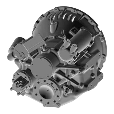
ZF Marine ZF 25 User manual

10
Operating Manual ZF/ZFE 25 A - ZF/ZFE 85 IV
ENGLISH
Section
1.1
Introduction
...............................
10
2.1
Gear Identification
....................
10
3.1
Description
...............................
10
4.1
Installation
.................................
11
5.1
Operation
...................................
11
6.1
Maintenance
.............................
12
7.1
Troubleshooting
........................
13
8.1
Technical Data
..........................
14
9.1
Warranty
...................................
14
10.1
List of recommended fluids
......
61
11.1
Dealer List
................................
62
12.1
Installation layout
.....................
63
13.1
Warranty Card
..........................
73
1.1
Introduction
1.1.1
C
USTOMER
’
S
R
ESPONSIBILIT
Y
The Customer/Operator is responsi
-
ble to perform the necessary safety
checks to ensure that lubrication, cool
-
ing, maintenance and recommended
practices are strictly followed for safe,
enjoyable operation.
All Transmission units are covered by
a guarantee. Therefore: In respect to
the handling of the transmission units
the instructions stated in this manual
are to be strictly followed.
C
AUTION
The manufacturer is not liable for
any damages or losses caused by
faulty installation, wrong handling
of the equipment and/or deficient
maintenance.
The Customer has to make sure,
that any external forces, as well
as vibration caused by torsion and
bending, are avoided.
The interaction between engine,
shaft and propeller may lead to
torsional vibration, producing a
hammering noise of gears and
might damage the engine and/or
transmission.
The Supplier is not liable for such
torsional vibration inherent to the
installation.
This manual includes, among others,
the following three main chapters:
1.1.2
D
ESCRIPTION
This part briefly describes function,
operation and design of the ZF/ZFE
types A/H/IV.
1.1.3
O
PERATION
This part describes the procedures for
Operation and all necessary safety
measures.
1.1.4
M
AINTENANCE
This part contains all maintenance and
service tasks to be performed by the
operator.
Whenever the terms «right, left, star
-
board, port» are used in this manual,
they always refer to the installed
transmission in direction of forward
movement.
Important information related to tech
-
nical reliability and operational safety
are highlighted by the identifying words
as follows:
WARNING
Any procedure, practice, condition,
statement etc., which is not strictly
followed, could result in injury or
death of personnel.
C
AUTION
Any procedure, practice, condition,
statement etc., which is not strictly
followed, could result in damage or
destruction of equipment.
N
OTE
:
Applies to technical require
-
ment to which the user of the equip
-
ment must pay particular attention.
WARNING,
C
AUTION
and
N
OTE
always precede the text to which they
apply.
2.1
Gear Identification
The identification plate is affixed to the
reverser.
An example of an identification plate
is shown in Fig. 1:
A
Transmission ratio propeller rota
-
tion opposite to a engine rotation.
B
Transmission Serial Number.
C
Every year a new progressive letter
is assigned.
D
Transmission part number.
E
Transmission version.
F
Transmission ratio propeller rota
-
tion same as engine rotation.
G
Transmission Type.
Significance of transmission designa
-
tions:
L
Version of transmission
H
Design of transmission
M
Nominal transmission ratio
I
Size of transmission
Position the control lever (refer to the rela
-
tive figures for the various models):
Figure 2: Type
ZFE 25 A-ZFE 45 A
- ZFE 63 A-ZFE 80 A
- ZFE 80 -1 A-ZFE 85 A
Figure 3: Type
ZFE 25 - ZFE 45-1
- ZFE 63.
Figure 4: Type
ZFE 63 IV - ZFE 80 IV
- ZFE 80-1 IV-ZFE 85 IV.
Figure 5: Type
ZFE
(Electronic
version).
Electric valves pos. «A» and «B» corre
-
spond to shifting lever «A» and «B» pos.
- Electric valves
12 V DC, 24 V DC.
- Version
A / H / IV.
3.1
Description
The ZF / ZFE A/H/IV marine trans
-
mission is a hydraulically activated
helical gear unit, developed for use in
commercial and pleasurecraft and de
-
signed as a three shaft type gearbox.
(Four shafts design for IV type).
The transmission is provided with a
disc-type reversing clutch mounted
on the input shaft and supplied with
hydraulic pressure from a fluid pump.
Operation of the fluid pump is depend
-
ent on the engine speed; the pump is
integrated in the control block.
The transmission is lubricated by
splash and force-feed lubrication.
3.1.1
ZFE OPTION
A head, astern, clutch disengagement
are operated electrically by ON/OFF
electric valves.
Electronic control block includes «get
home» features as well.
A simple mechanical device permits
manual engagement of the clutch.
Figure 6:
1
From cooler
2
Neutral safety switch
3
To cooler
4
Connecting thread for temperature
sensor
5
Control block
6
Connection for shifting pressure
control

11
Operating Manual ZF/ZFE 25 A - ZF/ZFE 85 IV
7
Output flange
8
Side mounting place
9
Fluid filter
10
Name plate
Figure 7:
1
Input shaft
2
Side mounting surface
3
Fluid dipstick
4
Shifting lever
5
Electric valves
6
Get home «Pos. A»
7
Get home «Pos. B»
4.1
Installation
When mounting the ZF Marine Arco
S.p.A. ZF/ ZFE transmissions, the
following items should be specially
noted:
•
Mounting should be done by a spe
-
cialist only.
•
Arrange the transmission and engine
correctly.
•
Align correctly with regard to engine
and propeller shaft.
•
Select a suitable damping coupling
between the engine and the trans
-
mission.
•
Choose adequate cooler.
•
Mount the transmission correctly in
the boat.
For detail information see Installation
on Manual.
Type of fluid:
ATF (Automatic Trans
-
mission Fluid); see chapter 10.1.
5.1
Operation
ll transmissions have been submitted
to a test run before shipment:
During normal operation, the transmis
-
sion should only be shifted with the
engine at idle speed.
In emergency cases it is also admis
-
sible to shift at higher speeds.
Optimum effectiveness of fluid can
only be assured, if fluid and filter are
changed regularly according to sched
-
ule (see chapter 6.1).
Visual checks for leakage should be
made from time to time.
WARNING
Work on the transmission must
only be performed with the engine
and propeller at standstill.
C
AUTION
Before the first start-up, the trans
-
mission must be filled with trans
-
mission fluid. For filling procedure,
fluid type, quantity and level refer to
chapter 6.1.5 fluid change.
C
AUTION
Using the transmission with an in
-
sufficient oil level will damage the
gears. An excessive oil level may
cause leakage at the shaft seals
and the transmission breather, and
raise the operating temperature
considerably.
5.1.1
O
PERATION
P
ROCEDURE
C
AUTION
Before operating the transmission,
check fluid level (see chapter 6.1.1).
C
AUTION
During normal operation, the trans
-
mission should only be shifted with
the engine at idle speed. Shifting at
higher engine speed may lead to
overstress of the friction disks of
the coupling and should be avoided
in normal operation.
N
OTE
:
The transmission may be
shifted from forward to reverse in case
of emergency, even at high engine
speed.
«A»
and
«H» V
ERSIONS
The transmission is shiftet by actuat
-
ing the shifting lever (figure 8) or the
electric valve (figure 9).
S
HIFTING
P
OSITIONS
(figure 8):
A =
Propeller rotation opposite of
engine rotation
N =
Neutral position
B =
Propeller rotation same as engine
rotation
«IV» V
ERSIONS
The transmission is shiftet by actuat
-
ing the shifting lever (figure 8) or the
electric valve (figure 9).
S
HIFTING
P
OSITIONS
:
A =
Propeller rotation same as engine
rotation
N =
Neutral position
B =
Propeller rotation opposite of en
-
gine rotation
WARNING
Start engine with transmission in
neutral only.
Operating temperature of the transmis
-
sion: 55÷80°C.A connection for a tem
-
perature probe has been provided.
C
AUTION
If the fluid temperature is too high,
stop engine immediately and check
transmission fluid level and oil
cooler for proper water flow.
Do not start the engine again until
the malfunction is eliminated.
NOTE:
«Get-home» (ZFE only).
In case of no electric supply to electric
valves; manual engagement of the
clutch «A» or «B» can be operated
manually:
-
Tighten the «get home screw» using
an allen wrench n° 3 (figure 10).
5.1.2
M
OVING
IN
TOW
OR
ANCHORING
When the boat moves in tow or is
anchored, the propeller may turn with
the water current.
This represents no danger for the
transmission. In a boat with two en
-
gines, the propeller of the unused
transmission may idle freely.
When the engine is off, the position of
the shifting lever is irrelevant.
WARNING
Do not work on the transmission
when being towed, or anchoring in
a river because the propeller may
rotate.
WARNING
Do not work on the transmission in
a twin engine boat, when one unit
is under power.
The propeller shaft of the inopera
-
tive transmission will rotate.
WARNING
When the engine runs idle, but the
propeller shaft should not be driven
(such as when charging the battery
with the generator), the shifting le
-

12
Operating Manual ZF/ZFE 25 A - ZF/ZFE 85 IV
ver (figure 12) must be held in the
neutral position (N) to prevent the
boat from moving.
Avoid to run the hydraulic gearbox
in neutral at high engine speed for
a long time.
6.1
Maintenance
6.1.1
F
LUID
LEVEL
CHEC
K
WARNING
Do not work on the transmission
when being towed, or anchoring in
a river because the propeller may
rotate.
Transmission fluid level may be
checked in cold or hot condition.
NOTE
: Always check the oil level be
-
fore operating the reverser. Proceed
as described below.
1)
Loosen fluid dipstick (figure 13, item
1) by turning the grip counterclock
-
wise.
2)
Wipe dipstick with a clean and
dustfree cloth.
3)
Insert dipstick do not screw in (fig
-
ure 14). Remove dipstick and check
fluid level: Fluid level has to be
between minimum and maximum
marks.
4)
Check O-rings (figure 14, item 1)
for damage, replace if necessary.
5)
Insert the dipstick and lock it by
turning the grip clockwise.
C
AUTION
According to the type and arrange
-
ment of the cooler and pipelines
a certain amount of oil will collect
after stopping the engine and will
flow back into the transmission after
a longer rest period. This may cause
the oil level in the transmission
to exceed the max. mark. Do not
remove off the surplus oil but pro
-
ceed according to steps 6 and 7.
6)
Let engine run at idle speed with
shifting lever in neutral position
until fluid cooler and all pipelines
are filled with fluid.
7)
Switch off engine and check fluid
level within a short time. If neces
-
sary, top fluid level off to the dipstick
mark. The fluid level on the dipstick
(figure 14) should be between the
min. and max. marks.The fluid level
must be checked again after a short
driving period.
6.1.2
F
LUID
C
HANGE
C
AUTION
The first change must be performed
after 25 hours of operation. All sub
-
sequent fluid changes to be made
after every 300 hours of operation
or once in a year (according to the
term which is reached earlier).
Note:
The filter element (figure 16,
item 1) must be replaced whenever
the fluid is changed.
C
AUTION
The old lubricant and oil filter
must be treated in the same way
as special waste that pollutes the
environment: they must therefore
be disposed of according to their
differentiated structure.
6.1.3
R
EMOVE
FLUID
FILTER
Proceed as described below to replace
the filter:
1)
Turn the screw that fixes the oil filter
cover in an anticounter-clockwise
direction and remove the filter from
its housing (fig. 15 pos. 1). Use a 6
mm Allen wrench.
2)
Pull filter element (figure 16, item
1) off.
3)
Check O-rings (figure 16, item 2
and 3) for damage, replace if nec
-
essary.
Only ZF 25 A - ZF 25 old version
(Fig. 22)
4)
Unscrew two M8x25 bolts (figure 22
item 1) and remove them together
with washers.
5)
Pull cover (figure 22, item 2), seal,
filter element off.
6)
Check seal for damage and filter for
wear. Replace if necessary.
6.1.4
D
RAINING
TRANSMISSION
FLUID
1)
ZF 45A, ZF 45-1, ZF 63A, ZF 63:
Push hose of suction pump (figure
17, item 1) through suction pipe
(figure 17, item 2) down to bottom of
the housing and remove the fluid.
2)
ZF 25 A
,
ZF 25, ZF 63 IV, ZF 80 A,
ZF 80-1A, ZF 80 IV, ZF 80-1IV, ZF
85 A, ZF 85 IV:
Remove the plug
(Fig. 18, item 1) and let the oil flow
from the proper hole.
N
OTE
:
Maximum outside diameter of
suction hose is 5/8 inch (16 mm).
6.1.5
F
ILLING
UP
WITH
T
RANSMISSION
F
LUID
Fill withATF oil for automatic gearboxes
according to the indicated quantities.
Add the quantity considered necessary
for filling the heat exchanger and rela
-
tive connection pipes (Fig. 19).
ZF 25 A:
........
1.91 US-qts (1,8 liters)
ZF 25:
........
2.12 US-qts (2,0 liters)
ZF 45 A:
........
2.65 US-qts (2,5 liters)
ZF 45-1:
..........
3.2 US-qts (3,0 liters)
ZF 63 A:
.............
4.2 US-qts (4 liters)
ZF 63:
..........
4.0 US-qts (3.8 liters)
ZF 63 IV:
..........
4.6 US-qts (4,4 liters)
ZF 80 A/ZF 80-1A:
.
5.8 US-qts (5.5 lt)
ZF 80IV/ZF 80-1IV:
...
7.4 US-qts (7.0 lt)
ZF 85 A:
................
5.8 US-qts (5.5 lt)
ZF 85 IV:
................
7.4 US-qts (7.0 lt)
Only use oil for automatic gearboxes,
as given in the specification in the «List
of recommended oils» on page 61.
6.1.6
I
NSERT
FLUID
FILTER
INTO
HOUSING
1)
Place new filter element onto cover
(Fig. 20).
2)
Lock the cover in its housing, fixing
it in place with the relative Allen
screw (fig. 21) and using a min. 5
Nm (4 ft/lbs) max 8 Nm (6 ft/lbs)
driving torque. Check the oil level
after a brief period of service.
Only ZF 25 A - ZF 25 old version
(Fig. 22)
3)
Place filter element and seal onto
cover.
4)
Lock filter cover in place by screw
-
ing in bolts (fig. 22 item 1), driving
torque 18 Nm (14 ft/lb);
6.1.7
T
RIAL
RUN
1)
Carry out a trial run after the oil
change.
2)
Set shifting lever to neutral position
(N). Start engine and let it run idle
for a short time to fill the cooler and
pipelines with transmission oil.

13
Operating Manual ZF/ZFE 25 A - ZF/ZFE 85 IV
7.1
Troubleshooting
First of all check, whether all items of operating instructions have been complied with.
SY
MPTOM
P
OSSIBL
Y
OSSIBL
OSSIBL
CAUSED
B
Y
R
EMED
Y
1. High fluid temperature
Fluid level high
Pump out fluid to max.
during operation
mark on dipstick
Fluid level low
Add fluid
Plugged or restricted
Replace cooler and flush
fluid cooler
water system
No water in cooling
Check cooling system
system
and repair
Unknown
Consult service station
2. Fluid on transmission
housing
Loose screws
Tighten to specification
Loose screw connections
Tighten, replace
Loose dipstick
Tighten, replace
Loose fluid filter
Tighten, replace
Fluid level high
Pump out fluid to max.
during operation
mark on dipstick
Unknown
Consult service station
3. Fluid and water mixed
Damaged fluid cooler
Consult service station
4. Shifts hard
Selector control
Consult service station
Linkage
Adjust
Unknown
Consult service station
5. Slow engagement
Selector control
Consult service station
Low fluid level
Add fluid
Linkage
Adjust
Unknown
Consult service station
6. No movement of the boat
Selector control
Consult service station
Improper selector position
Adjust
Low fluid level
Add fluid
Propeller missing
Replace
Propeller shaft broken
Consult service station
Transmission malfunction
Consult service station
Engine malfunction
Consult service station
No electric supply to electric
Plug to be fitted
valves (ZFE only)
Consult service station
In case of emergency
«Get home» feature can be
used (see pag. 10).
3)
Stop the engine and check oil level
again.
If necessary, replenish with oil.
Excessive oil should be removed.
The fluid level on the dipstick
should be between the min. and
max. marks.
The fluid level should be checked
again after a short driving period.
6.1.8
S
TORAGE
If the transmission is stored for longer
time, for example winter storage, it
should be topped off through the dip
-
stick hole with ATF to prevent the unit
from corrosion.
C
AUTION
Change the fluid when putting the
unit into operation again.

14
Operating Manual ZF/ZFE 25 A - ZF/ZFE 85 IV
8.1
Technical Data
Type
ZF 25
ZF 25A
ZF 45 A
ZF 45-1
ZF 63 A
ZF 63
ZF 63 IV
ZF 80 A
ZF 80 IV
ZF 85 A
ZF 85 IV
ZF 80-1 A
ZF 80-1 IV
Shifting pressure bar (psi)
21.5-23.5
21.5-23.5
21.5-23.5
21.5-23.5
21.5-23.5
21.5-23.5
21.5-23.5
21.5-23.5
21.5-23.5
23.5-26.5
23.5-26.5
(312-341)
(312-341)
(341-385)
(341-385)
(312-341)
(312-341)
(312-341)
(312-341)
(312-341)
(312-341)
(312-341)
23.5-26.5
23.5-26.5
(341-385)
(341-385)
Max. input speed
5500
5500
5500
5500
5500
5500
5500
4500
3300
4500
3300
min.
-1
(rpm)
3200
3200
3200
3200
3200
3200
3200
3200
3200
3200
3200
Weight without fluid and fluid
24 (53)
24 (53)
28 (62)
60 (132)
44 (97)
46 (101)
62 (136)
64 (141)
93 (205)
-
-
cooler kg (lb.)
Fluid capacity without
2.0 (2.12)
1.8 (1.91)
2.5 (2.65)
3.0 (3.2)
4.0 (4.2)
3.8 (4.0)
4.4 (4.6)
5.5 (1.5)
7.0 (1.85)
-
-
fluid cooler (Liters) (qts.)
9.1
Warranty
9.1.1
S
TANDARD
W
ARRANT
W
W
Y
ZF Marine Arco S.p.A. warrants its type
ZF / ZFE Reversing Marine Transmis
-
sion to be free from defects in material
and work-manship under normal use
and maintenance, provided that this
warranty shall apply if, and only if, the
equipment has been properly installed
and operated.
The obligation of ZF Marine Arco
S.p.A. under this warranty shall be
limited to the replacement or repair, at
its choice, of any part or parts found to
be defective by ZF Marine Arco S.p.A.
upon its examination of same, provided
that the part or parts are returned to the
nearest official ZF Marine Arco S.p.A.
distributor, freight prepaid, within the
time:
Twenty-four (24) months from date of
commissioning or thirty-six (36) months
from date of delivery to engine manu-
facturer, whichever occurs first.
The obligations of ZF Marine Arco
S.p.A. under this warranty as set forth
herein shall also be subject to com
-
pliance by the distributor or engine
manufacturer who has purchased the
product with the Warranty Procedures
which is made a part of this warranty.
All warranties shall run to distributors
and engine manufacturers who have
purchased the type ZF Reversing Ma
-
rine Transmission. This warranty shall
not apply to any part or parts which
have been repaired or altered, without
the prior written consent of an official
ZF Marine Arco S.p.A. dealer.
This warranty shall not apply if the
product or any of its components or
parts have been subject to misuse,
abuse, negligence, alteration, or ac
-
cident, or have not been operated in
accordance with printed instructions
of ZF Marine Arco S.p.A. or has been
operated under conditions more se
-
vere than, or otherwise exceeding,
those set forth in the specifications for
said product, or has been improperly
installed or reinstalled, or improperly
maintained and operated.
This warranty is expressly in lieu of all
other warranties expresses or implied
including the warranties of merchanta
-
bility and fitness for use and of all other
obligations including without limitation,
consequential damages, and ZF Ma
-
rine Arco S.p.A. neither assumes nor
authorizes any other person to assume
for ZF Marine Arco S.p.A., any other
liability in connection with the sale of
the ZF/ZFE Reversing marine trans
-
mission. ZF Marine Arco S.p.A. shall
in no event be liable for any breach of
warranty in an amount exceeding the
purchase price of the ZF/ZFE Revers
-
ing marine transmission.
9.1.2
TORSIONAL
RESPONSIBILIT
Y
AND
Y
TORSIONAL COUPLINGS
The responsibility for ensuring torsional
compatibility rests with the assembler
of the drive and driven equipment.
ZF Marine Arco S.p.A. can accept no
liability for gearbox noise caused by
vibrations or for damage to the gear
-
box, the flexible coupling or to other
*
Pleasure duty
**
Continuos duty
*
**
parts of the drive unit caused by this
kind of vibration. Contact ZF Marine
Arco S.p.A. for further information and
assistance.
ZF Marine Arco S.p.A. recommends
the use of a torsional limit stop for
single engine powered boats, wherein
loss of propulsion power can result in
loss of control. It is the buyer’s respon
-
sibility to specify this option, which can
result in additional cost and a possible
increase in installation length.
ZF Marine Arco S.p.A. can accept no
liability for personal injury, loss of life,
or damage or loss of property due to
the failure of the buyer to specify, a
torsional limit stop.
ZF Marine Arco S.p.A. selects torsional
couplings on the basis of nominal input
torque ratings and commonly accepted
rated engine governed speeds.
Consult ZF Marine Arco S.p.A. for
details concerning speed limits of
standard offering torsional couplings,
which can be less than the transmis
-
sion limit. Special torsional couplings
may be required for Survey Society Ice
Classification requirements.
This manual suits for next models
12
Table of contents
Other ZF Marine Microphone System manuals