Zhumell Vista 25x100 User manual

V
VISTA
ISTA
C
COIN
OIN-O
-O
PERATED
PERATED
B
BINOCULARS
INOCULARS

WARNINGS
•Bolt all pieces together to ensure stability.
•Do not attach power supply until assembly is completed.
Risk of electric shock.
•When disassembling, disconnect all cables to avoid
breakage or shock.
•Mount only on stable, level ground or platform.
•Secure base to Mounting platform to prevent
injury.
•Mount binoculars in dry area to increase
longevity.
•Maintain a clear pathway around binocu-
lars to prevent user injury.
FEATURES
•Weather Resistant Coating
•Multi-coated Optics
•AC or Battery Power Selection (12V Battery and 110V power
cord supplied)
•Adjustable Viewing Time Setting (0-50 mins./coin)
•Rechargeable 12V Battery for Remote
Mounting Locations.
•External Interpupillary Distance Adjustment
•Coin-operated, Always Open, and service opera-
tion modes
•Tamper-resistant Locking Coin Housing

S
PECIFICATIONS
OPTICAL
25x100 40x100
POWER 25x 40x
EXIT PUPIL 4mm 2.5mm
EYE RELIEF 14mm 8.2mm
FIELD OF VIEW 43.6m@1000m 26.2m@1000m
RESOLUTION 2.4” 2.4”
FOCUS RANGE 30m ~ ∞60m ~ ∞
MECHANICAL
ORIENTAL RANGE: 0~315°
UPRANGE: 0~30°
DOWN RANGE:0~45°
EYEPIECE DISTANCE RANGE: 58~72mm
SIZE OF BINOCULARS: 550x250x240mm
WHOLE HEIGHT: 1.5m (5ft.)
WHOLE WEIGHT: 84kg (185lbs.)
COIN DIAMETER RANGE:18~31mm
COIN THICKNESS RANGE:1.2mm~3.0mm
ELECTRICAL
POWER SUPPLY 85~265VAC (47~440HZ)
DC12V±1.5V
LOW DC POWER INDICATION: BELOW 10.5V
ENVIRONMENTAL
OPERATING ENVIRONMENT:14°F~104°F (-10°C~40°C)

INSTALLATION
Mount the pier base on stable, level ground using the included
mounting bolts. Anchor bolts into concrete or steel base which is
either anchored securely to the ground or a minimum of 10’ in diame-
ter to ensure stability. If improperly mounted, the unit may tip.
BASE INSTALLATION
Mount pier to base by inserting raised ring on pier into base open-
ing and securing with M10X20 mounting bolts (included) through
pre-drilled holes. Tighten bolts to ensure stability.
Secure base to mounting platform where unit will be used. (See
base installation below)
Attach mounting plate to top of control box with raised ring fac-
ing up. Secure mounting plate to control box using M2.5X5 hex
bolts (included). Tighten bolts to ensure stability.
Mount binoculars by setting them atop the mounting plate so
that mounting plate ring is centered in recess on the binocular
base and control cord enters the control box through the center hole
of the mounting plate. Attach binoculars to mounting plate using
M6X20 bolts (included). Tighten bolts to ensure stability.
Thread shutter control cable from binoculars onto shutter connec-
tion being careful not to bend connection prongs.
ASSEMBLY
1
2
3
4
5

IPD ADJUSTMENT
ELEVATION ADJUSTMENT
GENERAL USE
To adjust the elevation
height of the binoculars,
place hands underneath
the binocular body in
front of the eyepieces and
lift up or pull down. The
binocular housing should
swivel up or down. The
elevation adjustment may
be a litttle stiff at first,
but should loosen up
with use.
ELEVATION ADJUSTMENT
To adjust the Interpupillary
Distance (IPD) between
the barrels, grasp the ridged
area of each barrel just in
front of the eyepieces and
spin inward or outward.
The IPD should be set so
that one image circle is seen
and viewing is comfortable
for the user.
INTEPUPILLARY DISTANCE
(IPD) ADJUSTMENT

Contains the switch which actuates
the shutter to allow viewing when a coin is inserted in the coin slot.
COIN ACTIVATION CONTROL
Removeable box in which coins are collected.
COIN DROP BOX
Removeable 12V battery provides an optional power
source for mounting away from AC power sources.
BATTERY
Contains the optional settings which allow for view-
ing time adjustment and power source selection as well as the pri-
mary fuse and on/off switch.
CONTROL BOX
COIN BOX LEGEND
Key-locking door
protects the mechani-
cal controls inside of
the coin box.
DOOR

CONTROLS L
EGEND
Four pronged socket into which the power
cable connects to bring power from the chosen power source to the
control panel.
POWER CONNECTION
Allows you to set the amount of time the shutter
will be open once actuated by a coin and controls all other shutter
settings.
TIMER SETTING
Houses one replaceable 0.75Amp fuse to protect
control panel electronics from power overload.
FUSE SOCKET
Allows you to choose
between 115V AC or 12V DC
power source.
CURRENT SELECTOR
Three pronged socket into which the
shutter control cable connects to the control panel.
SHUTTER CONNECTION
Allows you to turn power on
or off for the unit.
POWER SWITCH
Display the amount of volt-
age being received by the
control panel.
VOLTAGE METER

To open the shutter for
viewing, place coin (quarter unless otherwise set)
in coinslot. Shutter will remain open for the amount
of time set internally (normally 30sec. to 1 min.).
SHUTTER ACTIVATION
To return a coin just inserted, press the silver coin
return button just beneath the coin slot immediately after inserting
coin. the coin will be returned in the slot below the coin return but-
ton.
COIN RETURN
SHUTTER INFO
To set the amount of time you would like
the shutter to stay open for each coin, use the settings on the control
panel timer setting. Using the range setting and timer dial, set the
shutter to be open from 0 - 50 mins.
SETTING SHUTTER TIME
To replace the control box fuse, unscrew fuse hous-
ing by turning counterclockwise. Pull the old fuse out of the fuse
housing and replace with a new 0.75Amp fuse. Replace fuse housing
in socket and tighten by turning clockwise. Be sure to use a 0.75Amp
fuse, as a higher powered fuse may result in electrical damage to the
control panel
REPLACING FUSE

TIMER S
ETTINGS
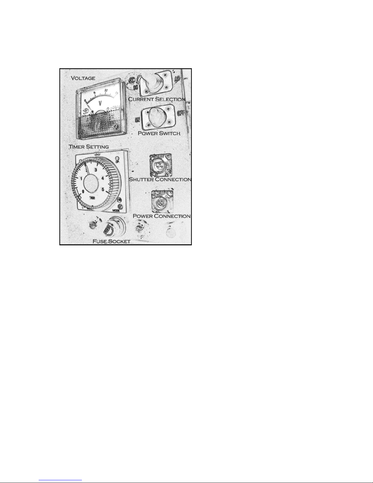
Range adjusts the timer dial to longer or shorter ranges of time
from which to shoose. To choose between smaller increments of time,
use a small screwdriver to turn the range setting counterclockwise.
For larger increments of time, turn the range setting clockwise.
RANGE
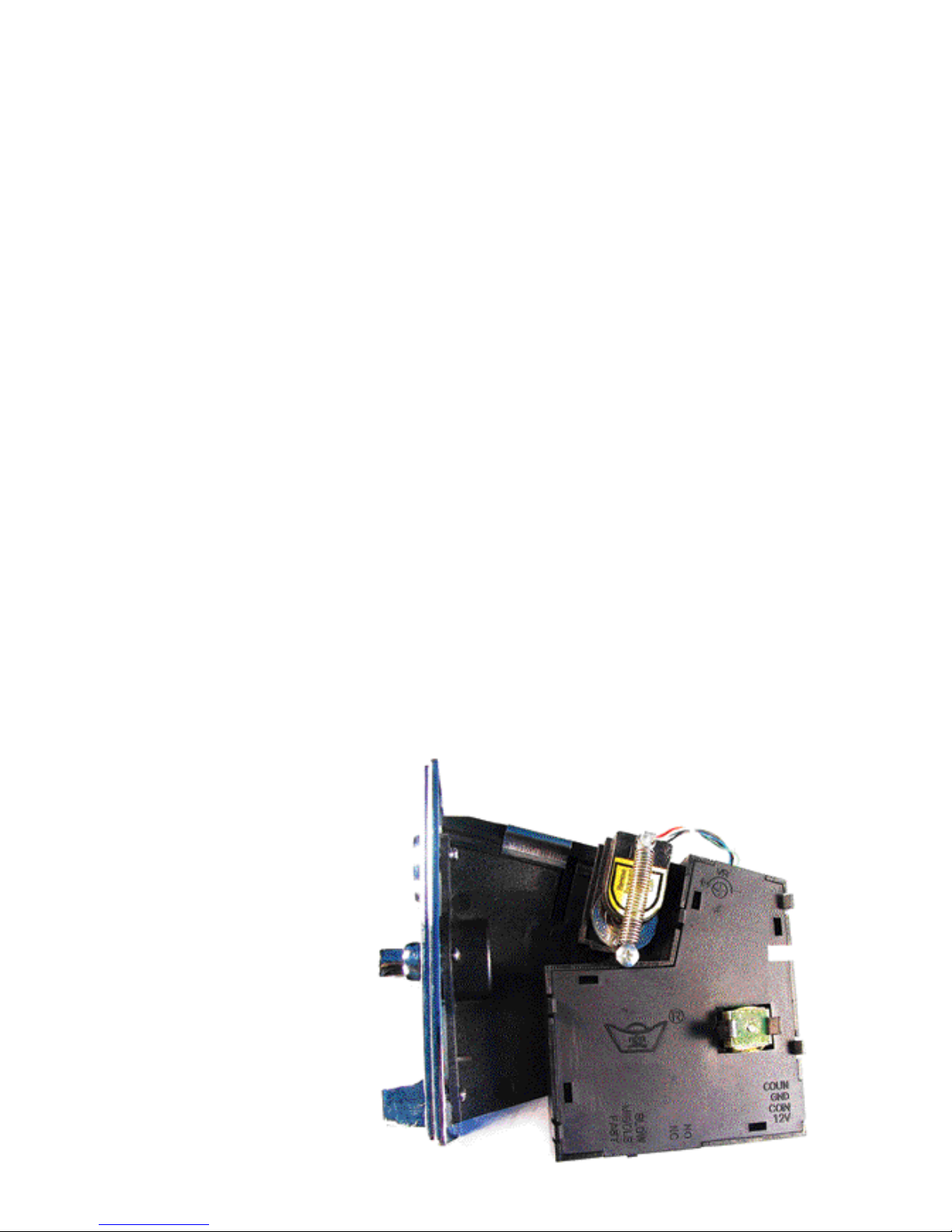
Mode allows you to access the different operating modes for
the Vista. The indicator window directly above the mode dial shows
what operating mode the Vista using a signifying letter. Turn the
mode control to the desired setting using a small screwdriver.
MODE
Once the desired range has been set, the timer dial
allows you to set the amount of time that the shutter will remain open
once actuated by a coin. The lower, central window states what
increment of time the numbers stand for.
TIMER DIAL
MODE SETTINGS
SF, OS, OF1 - Standard Operating
Modes: Shutter is opened when coin is
inserted.
FL, FO - Flash Modes: shutter is alter-
nated between open and closed accord-
ing to time setting.
ON, OF - Open Modes: Shutter is
opened and remains open until
switched to a different mode.
OC - Open/Close Mode: Shutter is
opened and closed quickly at end of
time setting.

COIN SETTING
The shutter release mechanism uses a tem-
plate coin to determine the size coin needed to open the shutter. In
order to set the appropriate coin size, a coin of the type to be used to
activate the shutter (eg. a quarter or token) must be inserted in the
template coin slot. To insert a coin into the template coin slot, first
remove the coin activation control by loosening the four bolts which
hold the coinslot faceplate on and disconnecting the communication
cable from the back of the coin activation control. Once coin activa-
tion control is removed, lift the template coin sensor (the plastic piece
above the template coin with wires attached to it) away from the
template coin slot. Remove the existing template coin and replace
with the type coin which will be used to activate the shutter.
Reinstall the coin activation control and tighten all bolts and the unit
should be ready for use.
SETTING COIN SIZE

V.
REPAIR P
ROCESS
THE ZHUMELL WARRANTY
We have designed Zhumell products to be durable and to offer excellent
value. Because we think it is important to stand behind that statement
what follows are the details of our warranty, one of the best warranties in
the industry.
Your Zhumell has a one-year warranty. For the warranty to be valid, the
Zhumell must be registered. This can be done quickly and easily at
www.zhumell.com or by calling: 800.922.2063.
To obtain warranty service to the damaged Zhumell call to speak with a
service representative at 800.922.2063.
When you return your Zhumell to us please send a letter that explains the
problem. This is important. Sometimes the problem is obvious as when we
open a box and the pieces fall out. However, sometimes Zhumell owners
are particular (that is why we love you) and a flaw that you have noticed
may be hard to find by our technician. A letter will speed up the warran-
ty process and save a phone call. (Oh, yes, please include your phone num-
ber and an address!)
We may have improved or changed our Zhumell products from the
time you first obtained yours, therefore it is our option to repair or
replace the Zhumells you sent us. (Please note that the maximum limit
of liability for losses or damage from any cause shall be the price paid
for the Zhumell. )
Box your Zhumell securely.
ONE-YEARWARRANTY
II.
I.
III.
IV.
Include a note explaining the reason the Zhumell needs repair.
Include your daytime phone number.
Include an address for returning your Zhumell to you.
Include shipping charge amount (from service representative).
We recommend that you send your unit to us by way of UPS or
FedEx. This provides a tracking number should your unit
become lost or damaged.
REPAIR CHECKLIST

Phone: (800)922-2063
Web: www.zhumell.com 30 E. Superior St.
Duluth, MN 55802
Other manuals for Vista 25x100
2
This manual suits for next models
1
Table of contents
Other Zhumell Binoculars manuals

Zhumell
Zhumell Covent 3x25 User manual

Zhumell
Zhumell 7X50 MARINE BINOCULARS User manual

Zhumell
Zhumell 20 x 80 SuperGiant User manual

Zhumell
Zhumell Zoom 12-60x80 User manual

Zhumell
Zhumell SHORT BARREL User manual

Zhumell
Zhumell Marine 7x50 User manual

Zhumell
Zhumell ZHUV002-1 User manual

Zhumell
Zhumell Tachyon 25x100 User manual

Zhumell
Zhumell Vista 25x100 User manual

Zhumell
Zhumell Vista User manual