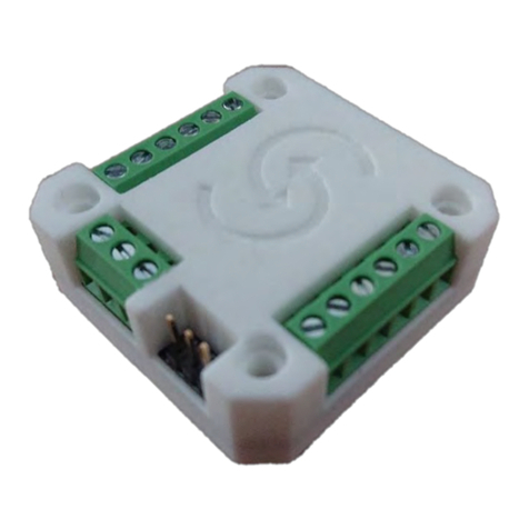
Zikodrive ZDBL50DCUART Series User manual

1
Zikodrive Motor Controllers is a trading name of Round Bank Engineering Ltd
Unit 4B, Top Land Business Park, Hebden Bridge, West Yorkshire, HX7 5RW enquiries@Zikodrive.com –www.Zikodrive.com - +44 (0) 1422
647177
Zikodrive ZDBL50DCUART Series Operating Manual V1.0

2
Zikodrive Motor Controllers is a trading name of Round Bank Engineering Ltd
Unit 4B, Top Land Business Park, Hebden Bridge, West Yorkshire, HX7 5RW enquiries@Zikodrive.com –www.Zikodrive.com - +44 (0) 1422
647177
Contents
Introduction .......................................................................................................................................3
Overview ........................................................................................................................................3
Specifications .................................................................................................................................3
Setting Up...........................................................................................................................................4
Programming Manual ........................................................................................................................6
The UART Protocol .........................................................................................................................6
Protocol Setup................................................................................................................................6
Recommended Software................................................................................................................6
The Zikodrive Protocol ...................................................................................................................7
CheckSum formula .........................................................................................................................7
Shortlist of Commands...................................................................................................................8
0x00 –Speed & Direction Register.................................................................................................9
0x01 –Parameters .......................................................................................................................11
0x02 –Move Distance..................................................................................................................12
0x03 –Emergency Stop................................................................................................................13
0x04 –Motor Mode .....................................................................................................................13
0x06 –Revert to PWM/Analogue Mode......................................................................................13
0x07 –PID Settings.......................................................................................................................14
Additional Information.....................................................................................................................14

3
Zikodrive Motor Controllers is a trading name of Round Bank Engineering Ltd
Unit 4B, Top Land Business Park, Hebden Bridge, West Yorkshire, HX7 5RW enquiries@Zikodrive.com –www.Zikodrive.com - +44 (0) 1422
647177
Introduction
Overview
This manual is intended to be used with the Zikodrive ZDBL50 SERIES UART compatible Motor
controllers running standard firmware (1.0) and includes the following UART Commands that can
also be used over RS232 or RS485 using the relevant Break Out Boards:
Setting up standard running features such as Speed & Direction Commands, Setting Parameters,
setting a move distance, Braking, switching between modes, Position read and setting PID
Specifications
•Up to 28Vdc.
•Up to 50Adc.
•Sensored BLDC trapezoidal/Block commutation control
•Four Optically Isolated Inputs
•Two Power Outputs (24V up to 2A)
•Modular design connects to many Break Out Boards that can provide options such as
420mA, 0-10Vdc etc...
•16bit high speed Microcontroller controlled.
5
Important NOTE:
It is critically important to not exceed the recommended input voltages as this may cause
unrepairable damage to the Zikodrive ZD SERIES UART Motor Driver. The max voltage
recommended for any digital or analogue inputs is 5Vdc. DO NOT APPLY Higher Voltage PWM as
this will damage the board.
All wires must be kept as short as possible to reduce EMC emissions from the motor phase cables
and to reduce noise on both the analogue and digital inputs. If you require more information

4
Zikodrive Motor Controllers is a trading name of Round Bank Engineering Ltd
Unit 4B, Top Land Business Park, Hebden Bridge, West Yorkshire, HX7 5RW enquiries@Zikodrive.com –www.Zikodrive.com - +44 (0) 1422
647177
Setting Up
Wiring Motor Phase Wires
The motor phase wires carry the supply voltage and high currents to and from the motor. It is
important not to get them wired up incorrectly as the motor will not turn may be possibility of
damage to either the motor and/or controller (possibly even PSU due to high currents).
Power Wires
12-28Vdc must be applied to the controller. The controller is NOT protected against reverse
polarity, so utmost care must be taken to ensure the wires are not reversed.
Note –Please ensure that the DC power supply has the proper current supply capability. Care
should be taken to ensure the DC supply signal is clean (keep wires as short as possible, and
shield where required).
Hall Sensor Inputs

5
Zikodrive Motor Controllers is a trading name of Round Bank Engineering Ltd
Unit 4B, Top Land Business Park, Hebden Bridge, West Yorkshire, HX7 5RW enquiries@Zikodrive.com –www.Zikodrive.com - +44 (0) 1422
647177
The hall sensor wires are low power signals coming from hall sensors within the motor, it is
critical that there is no noise on these lines to prevent the motor malfunctioning. Screening the
hall wires and grounding only one end (to prevent GND loops) may be necessary. Also, be sure to
try and keep these wires as short as possible.
UART Connections
The RX and the TX pins must be connected to the Master Controller. I.e., TX (transmitting) from
the
Master controller must be connected to the RX (receiving) pin on the ZDBL50DC controller. The
TX
(transmitting) from the ZD SERIES UART must be connected to the RX (receiving) of the Master
Controller.
The UART lines are low power signal (3V3) and must be kept as short as possible and should be
screened where necessary.
PWM/Analogue Input
The PWM/Analogue input is a standard 12bit analogue input with additional protection and
filters. It is recommended to use a high frequency PWM signal (100Khz+) to ensure a clean signal
and smooth motion of the motor.
Direction Input
The Direction input is only used in PWM/Analogue mode. The input needs to be pulled to the
Control GND to switch direction and released (open circuit) to return to the original direction
(i.e., the input has internal pull up resistors to 3V3).

6
Zikodrive Motor Controllers is a trading name of Round Bank Engineering Ltd
Unit 4B, Top Land Business Park, Hebden Bridge, West Yorkshire, HX7 5RW enquiries@Zikodrive.com –www.Zikodrive.com - +44 (0) 1422
647177
Programming Manual
The UART Protocol
The protocol used is non-standard and derived by the Zikodrive engineers to provide fast and
efficient data transfer.
The Data is transmitted and received in 10 packets of 8bit binary Bytes.
Protocol Setup
BAUD RATE
=
19200
START BITS
=
One
STOP BITS
=
One
PARITY
=
None
Recommended hardware
TTL-232R-3V3
Recommended Software
Realterm serial/TCP Terminal that can be downloaded here from sourceforge
There is ongoing development for Zikodrive own software ZDSoft to incorporate the ZDBL series
of controllers soon.

7
Zikodrive Motor Controllers is a trading name of Round Bank Engineering Ltd
Unit 4B, Top Land Business Park, Hebden Bridge, West Yorkshire, HX7 5RW enquiries@Zikodrive.com –www.Zikodrive.com - +44 (0) 1422
647177
The Zikodrive Protocol
All commands are initiated with a two-byte header, one-byte address code, one-byte register
address, 5 data bytes and then followed with a single Checksum byte. To ensure the correct data
is being transferred, the protocol will send either a confirm (0x06) or a reject (0x15) for a good,
or a bad command. If the ZD SERIES UART has accepted the command, the confirmation will then
be sent to the Master Controller and then process the given command. If the command was
rejected, all data will be disregarded with a NACK (0x15) and error code, and a new command
must be sent.
Example 1 –Basic Command
From Master 0x7A 0x64 0x01 0x02 0x00 0x00 0x00 0x0E 0x10 0xDE
0x7A
=
Header, ASCII code “Z”
0x64
=
Header, ASCII code “D”
0x01
=
Zikodrive Address, Set as 0x01 as default
0x02
=
Register, states which command/action you wish to change
0x00
=
Data byte 0
0x00
=
Data byte 1
0x00
=
Data byte 2
0x0E
=
Data byte 3
0x10
=
Data byte 4
0xDE
=
Checksum
CheckSum formula
Each command sent to the Zikodrive controller must be followed with a CheckSum byte or the
data will be rejected.
CHECKSUM = ((ADDRESS + REGISTER + DATA0 + DATA1 + DATA2 + DATA3 + DATA4) XOR 0xFF) & 0xFF;
The Address, the required register and the data bytes are all added together.
Command is run through an XOR with 0xFF
Command is then run through & with 0xFF

8
Zikodrive Motor Controllers is a trading name of Round Bank Engineering Ltd
Unit 4B, Top Land Business Park, Hebden Bridge, West Yorkshire, HX7 5RW enquiries@Zikodrive.com –www.Zikodrive.com - +44 (0) 1422
647177
We have available a Checksum Calculator on an EXCEL spreadsheet to help calculate the
CheckSum byte if required.
Please note that the Header and the CheckSum bytes are not included in the CheckSum Formula.
Shortlist of Commands
Register
Name
Byte Data
Default
0x00
Speed & Direction
Data 0 = Direction setting
Data 1 = NA
Data 2 = NA
Data 3 = Speed MSB
Data 4 = Speed LSB
0x00
0x00
0x00
0x00
0x00
0x01
Parameters
Data 0 = NA
Data 1 = Max Current
Data 2 = Reaction
Data 3 = Move Distance Speed MSB
Data 4 = Move Distance Speed LSB
0x00
0x0F
0x46
0x00
0x00
0x02
Move Distance
Data 0 = Direction
Data 1 = Distance MSB
Data 2 = Distance LMSB
Data 3 = Distance MLSB
Data 4 = Distance LSB
0x00
0x00
0x00
0x00
0x00
0x03
Emergency Stop
Data 0-4 NA
0x00
0x04
Motor Mode
Data 0 = Mode
0x00
0x05
Read Distance
Data 0 = NA
Data 1 = Distance MSB
Data 2 = Distance LMSB
Data 3 = Distance MLSB
Data 4 = Distance LSB
0x00
0x00
0x0F
0x42
0x40
0x06
Revert to PWM/Analogue
Data 0-4 NA
NA
0x07
PID Settings
Data 0 = PID Enable
Data 1 = Commutation Points
Data 2 = Proportional Value
Data 3 = Integral Value
Data 4 = Derivative Value
0x01
0x0F
0x64
0x00
0x00

9
Zikodrive Motor Controllers is a trading name of Round Bank Engineering Ltd
Unit 4B, Top Land Business Park, Hebden Bridge, West Yorkshire, HX7 5RW enquiries@Zikodrive.com –www.Zikodrive.com - +44 (0) 1422
647177
0x00 –Speed & Direction Register
This register sets the motor running in a set speed and direction.
Register
Name
Byte Data
Default
0x00
Speed & Direction
Data 0 = Direction setting
Data 1 = NA
Data 2 = NA
Data 3 = Speed MSB
Data 4 = Speed LSB
0x00
0x00
0x00
0x00
0x00
The actual motor direction depends on the wiring order and motor windings. However, if “Byte
0” is equal to 0, the direction will be “A”, and if “Byte 0” is equal to 1, the direction will be “B”.
Data Bytes 1 & 2 are not required and will not be read.
The speed refers to the PWM being sent into the motor windings. If a value of 0 is sent, the
motor will stop, and if a value of 1850 the PWM will be at maximum duty cycle.
Example 2
From Master
0x7A
0x64 0x01 0x00 0x01 0x00 0x00 0x03
0x9D
0x5D
0x7A & 0x64
=
Header
0x01
=
Address
0x00
=
Register –Speed & Direction register
0x01
=
Data Byte 0 –Direction –Move in Direction “B”
0x00
=
Data Byte 1 –Not read
0x00
=
Data Byte 2 –Not read
0x03
=
Data Byte 3–Speed Value MSB
0x9D
=
Data Byte 4 –Speed Value LSB
0x5D
=
Checksum
Speed variable
=
0x39D (HEX)
=
925 (Decimal)

10
Zikodrive Motor Controllers is a trading name of Round Bank Engineering Ltd
Unit 4B, Top Land Business Park, Hebden Bridge, West Yorkshire, HX7 5RW enquiries@Zikodrive.com –www.Zikodrive.com - +44 (0) 1422
647177
As 925 is half the max 1850, the motor will move in direction “B” at half the PWM duty cycle. This
varies depending on what motor is used.
If the PID in register 0x07 is enabled, the Speed value is used as a reference speed. This will vary
depending on the number of poles in the motor.

11
Zikodrive Motor Controllers is a trading name of Round Bank Engineering Ltd
Unit 4B, Top Land Business Park, Hebden Bridge, West Yorkshire, HX7 5RW enquiries@Zikodrive.com –www.Zikodrive.com - +44 (0) 1422
647177
0x01 –Parameters
This register is used to set up the Maximum motor current, the reaction speed of the motor and
Move Distance speed setting.
Register
Name
Byte Data
Default
0x01
Parameters
Data 0 = NA
Data 1 = Max Current
Data 2 = Reaction
Data 3 = Move Distance Speed MSB
Data 4 = Move Distance Speed LSB
0x00
0x0F
0x46
0x00
0x00
When the Max Current is measured in the motor phase windings, the PWM supplied to the
windings will be reduced to prevent an over current failure in the motor, application or
controller.
The reaction speed is only used when the PID is NOT enabled. The reaction speed varies the
acceleration and deceleration rate of the motor. Smaller values result in a much more responsive
motor, and higher values result in a more laid-back motor.
The move distance speed refers to the maximum speed the motor will accelerate up to while
performing a Move Distance command (0x03).

12
Zikodrive Motor Controllers is a trading name of Round Bank Engineering Ltd
Unit 4B, Top Land Business Park, Hebden Bridge, West Yorkshire, HX7 5RW enquiries@Zikodrive.com –www.Zikodrive.com - +44 (0) 1422
647177
0x02 –Move Distance
This register sets the motor running for a set distance at a set speed and direction.
Register
Name
Byte Data
Default
0x02
Move Distance
Data 0 = Direction
Data 1 = Distance MSB
Data 2 = Distance LMSB
Data 3 = Distance MLSB
Data 4 = Distance LSB
0x00
0x00
0x00
0x00
0x00
As default (can be changed by Zikodrive) the output is scaled to count every 6-motor
commutation point as a single unit of distance. So, for a 5-pole motor you will get 30
commutation points per revolution (5*3 [hall sensors], *2 [counts both the rise and falls of hall
sensors]) which will result in 5 distance units per motor revolution. Page
Example 3
From Master
0x7A
0x64 0x01 0x02 0x00 0x00 0x00 0x0E
0x10
0xDE
0x7A & 0x64
=
Header
0x01
=
Address
0x02
=
Register –Move Distance
0x00
=
Data Byte 0 –Direction –Move in Direction “A”
0x00
=
Data Byte 1 –MSB
0x00
=
Data Byte 2 –LMSB
0x0E
=
Data Byte 3–MLSB
0x10
=
Data Byte 4 –LSB
0xDE
=
Checksum
This gives us a total move distance of 0xE10 = 3600 move units, which equals 3600/6 = 600
motor revolutions.

13
Zikodrive Motor Controllers is a trading name of Round Bank Engineering Ltd
Unit 4B, Top Land Business Park, Hebden Bridge, West Yorkshire, HX7 5RW enquiries@Zikodrive.com –www.Zikodrive.com - +44 (0) 1422
647177
0x03 –Emergency Stop
This register sets into an abrupt stop
Register
Name
Byte Data
Default
0x03
Emergency Stop
Data 0-4 NA
0x00
This command will stop the motor almost immediately. Care should be taken when using this
command from high speed as it will put many components within the system under a large
amount of stress.
0x04 –Motor Mode
This register sets the power bridge configuration into one of two different modes. Normal
running conditions will resume when the appropriate UART command is received.
Register
Name
Byte Data
Default
0x04
Motor Mode
Data 0 = Mode
0x00
If mode = 0, normal running
If mode = 1, motor will free wheel
If mode = 2, motor will all 3 low side mosfets to use the motor Bemf as an electronic brake.
Page
0x06 –Revert to PWM/Analogue Mode
This register will set the controller back into reading the PWM/Analogue pin. As soon as the
controller received another UART signal, the controller will return to UART mode again.
Register
Name
Byte Data
Default
0x06
Revert to PWM/Analogue
Data 0-4 NA
NA
In this case it does not matter what any of the Data Bytes say as it is all ignored by the controller.

14
Zikodrive Motor Controllers is a trading name of Round Bank Engineering Ltd
Unit 4B, Top Land Business Park, Hebden Bridge, West Yorkshire, HX7 5RW enquiries@Zikodrive.com –www.Zikodrive.com - +44 (0) 1422
647177
0x07 –PID Settings
This register will set PID settings, this register will need to be tuned for most motors and
applications.
Register
Name
Byte Data
Default
0x07
PID Settings
Data 0 = PID Enable
Data 1 = Commutation Points
Data 2 = Proportional Value
Data 3 = Integral Value
Data 4 = Derivative Value
0x01
0x0F
0x64
0x00
0x00
0x06
Revert to PWM/Analogue
Data 0-4 NA
NA
Internally the micro controller will divide the values received by 100. So, the default 0x64 value
for the proportional term gives us a decimal value of 100, which means that the value the micro
controller uses in the PID algorithm is “1”.
Additional Information
If you need any additional information for any of the information in this document, please
contact Zikodrive Motor Controllers at the details on the footer of every page.
Table of contents
Other Zikodrive Controllers manuals
Popular Controllers manuals by other brands

Panasonic
Panasonic ACXF60-03410 installation manual

Altronix
Altronix eFlowNA8 Series installation guide

Husky
Husky HDA707 Operating instructions & parts manual

Emerson
Emerson Bettis SCE300 Installation, operation and maintenance manual

Nortek
Nortek GoControl WT00Z-1 quick start guide

Unipulse
Unipulse F160 Operation manual