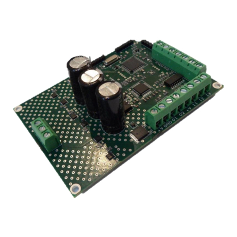
Zikodrive ZDSMUL2-24 User manual

1
Zikodrive Motor Controllers are a product of Round Bank Engineering Ltd
www.zikodrive.com - +44 (0) 1422647177
Zikodrive ZDSMUL2-24 Stepper DC Motor Controller Quick Start Guide
Document Number
Revision
Date
Authorised by
1-0092-A
A
26/10/2021
AC

2
Zikodrive Motor Controllers are a product of Round Bank Engineering Ltd
Floor 2, Clifton Warehouse, Sowerby Bridge, West Yorkshire, HX6 2BY enquiries@Zikodrive.com –
www.zikodrive.com - +44 (0) 1422647177
Contents
Introduction....................................................................................................................................................... 4
Specification ...................................................................................................................................................... 4
Connections on the ZDSMUL2-24...................................................................................................................... 5
Wiring Motor Phase Wires ................................................................................................................................ 6
Connecting the Power....................................................................................................................................... 6
Setting up the ZDA010 Controller Host programme......................................................................................... 7
Things you will need...................................................................................................................................... 7
Getting started .............................................................................................................................................. 7
Using the ZDA010 software to set parameters............................................................................................... 10
Key Values........................................................................................................................................................ 11
Step Size....................................................................................................................................................... 11
Interpolate................................................................................................................................................... 11
Enable Input................................................................................................................................................. 12
Connecting the enable input ................................................................................................................... 12
Direction Input............................................................................................................................................. 12
Connecting the direction input................................................................................................................ 12
Current Setting ........................................................................................................................................ 13
Holding Current ....................................................................................................................................... 14
Set RPM ................................................................................................................................................... 14
Acceleration & Deceleration Scalar............................................................................................................. 14
Voltage Minimum........................................................................................................................................ 15
Read Speed.................................................................................................................................................. 15
Fault............................................................................................................................................................. 15
Analogue RPM Limit .................................................................................................................................... 15
Output ......................................................................................................................................................... 16
Other Inputs/Outputs...................................................................................................................................... 17
Analogue Speed Input ..................................................................................................................................... 18
UART................................................................................................................................................................ 18
Troubleshooting .............................................................................................................................................. 19
Revisions.......................................................................................................................................................... 20
A:.............................................................................................................................................................. 20

3
Zikodrive Motor Controllers are a product of Round Bank Engineering Ltd
Floor 2, Clifton Warehouse, Sowerby Bridge, West Yorkshire, HX6 2BY enquiries@Zikodrive.com –
www.zikodrive.com - +44 (0) 1422647177
B:.............................................................................................................................................................. 20
C:.............................................................................................................................................................. 20
RETURNS.......................................................................................................................................................... 21
WARRANTY...................................................................................................................................................... 21

4
Zikodrive Motor Controllers are a product of Round Bank Engineering Ltd
Floor 2, Clifton Warehouse, Sowerby Bridge, West Yorkshire, HX6 2BY enquiries@Zikodrive.com –
www.zikodrive.com - +44 (0) 1422647177
Introduction
This quick start guide provide an overview of how to setup and operate the ZDSMUL2-24 stepper
motor controller. Please read in full before setting the controller up and if you have any questions
or are unsure anything please contact our customer service team via our website
(www.zikodrive.com) and we will be happy to help.
NOTE; YOU MUST ENSURE THAT YOU CONNECT THE CORRECT POWER AND VOLTAGE TO THE
CONTROLLER. EXCEEDING THESE LIMITS WILL DAMAGE THE CONTROLLER PERMANENTLY AND
VOID ANY WARRANTIES.
Specification
• 5-24Vdc
• Up to 1.8A current
• Up to 1/256 microstepping
• UART connectivity
• Programmable Output pin
• Controllable via Step Input
• Analogue / UART controllable speed
• Controllable direction controlled by input / UART
• -20 to 50C

5
Zikodrive Motor Controllers are a product of Round Bank Engineering Ltd
Floor 2, Clifton Warehouse, Sowerby Bridge, West Yorkshire, HX6 2BY enquiries@Zikodrive.com –
www.zikodrive.com - +44 (0) 1422647177
Connections on the ZDSMUL2-24
NOTE: YOU MUST ONLY CONNECT THE MAIN POWER SUPPLY TO THE VS AND GND PINS ON THE
TOP LEFT (MARKED RED AND BLACK). DO NOT CONNECT THE MAIN POWER SOURCE GND TO ONE
OF THE OTHER GND CONNECTIONS.
VS
GND
B+
A+
B-
A-
DIR
STP
OUT
3V3
FLT
EN
GND
ANL
RX
GND
TX
3V3

6
Zikodrive Motor Controllers are a product of Round Bank Engineering Ltd
Floor 2, Clifton Warehouse, Sowerby Bridge, West Yorkshire, HX6 2BY enquiries@Zikodrive.com –
www.zikodrive.com - +44 (0) 1422647177
Wiring Motor Phase Wires
Please consult the stepper motor datasheet when wiring up the motor to ensure you have the right
connections in place. A typical stepper motor will have the following connections.
Terminal
Wire
A-
Green
A+
Black
B-
Red
B+
Blue
Connecting the Power
5-24Vdc must be applied to the board on the terminals marked in “Connections on the ZDSMUL2-24”
above. Connect the power to VS and the ground to the GND connection next to this. Once all these
connections are complete, the Motor controller can be powered up and the device connected to the
ZDA010 software for setup. If the controller is powered, you will see a green light shining through the
casing.

7
Zikodrive Motor Controllers are a product of Round Bank Engineering Ltd
Floor 2, Clifton Warehouse, Sowerby Bridge, West Yorkshire, HX6 2BY enquiries@Zikodrive.com –
www.zikodrive.com - +44 (0) 1422647177
Setting up the ZDA010 Controller Host programme
Things you will need
1. ZDA010 software (this will either have been supplied on a memory stick or can be downloaded
from www.zikodrive.com)
2. An .ini file to assist with parameter setup.
3. A ZDSMUL2-24 controller with power source.
4. A 3.3V FTDI cable (a TTL-232R-3V3 cable is available for purchase from www.zikodrive.com)
5. A computer or laptop with USB connection.
Getting started
1. Connect the 3.3V FTDI cable to the controller as per the instructions on your FTDI cable and the
connections set out above. For the TTL-232R-3V3 cable the connections are - RX = Orange, TX =
Yellow, GND = Black.
2. Open the ZDA010 software.
When opening the ZDA010 software, you will need to set it up. Please ensure that the inputs are connected
appropriately as per the photo above. You may need to check your FTDI cable instructions to be certain of
the connection, however the above image is a typical example.

8
Zikodrive Motor Controllers are a product of Round Bank Engineering Ltd
Floor 2, Clifton Warehouse, Sowerby Bridge, West Yorkshire, HX6 2BY enquiries@Zikodrive.com –
www.zikodrive.com - +44 (0) 1422647177
3. Upon opening the terminal, You must then load the .ini file for the ZDSMUL2-24 stepper motor
controller. This can be done by going to File > Load Config and then selecting the .ini file supplied.
This file is used to set all the key parameters and varies from controller to controller so it is
important to make sure you have the correct file selected.
4. You must then go to COM > Settings.

9
Zikodrive Motor Controllers are a product of Round Bank Engineering Ltd
Floor 2, Clifton Warehouse, Sowerby Bridge, West Yorkshire, HX6 2BY enquiries@Zikodrive.com –
www.zikodrive.com - +44 (0) 1422647177
Then change the COM port to the one you are using (THIS WILL VARY FROM DEVICE TO DEVICE –contact
us if you are having trouble connecting to the COM port). Set the BAUD rate to 57600, Data bits to 8, and
Parity to none.
5. Once the Communication settings have been changed, you will need to open the port by going to
COM > Open. On the bottom left of the window, you should then see the COM port open with the
settings as below.
If you can see the COM port open and the settings as indicated in the image on the right then you have
now successfully connected to the controller and are able to set key parameters.

10
Zikodrive Motor Controllers are a product of Round Bank Engineering Ltd
Floor 2, Clifton Warehouse, Sowerby Bridge, West Yorkshire, HX6 2BY enquiries@Zikodrive.com –
www.zikodrive.com - +44 (0) 1422647177
Using the ZDA010 software to set parameters
Please note, these settings may change depending on the .ini file you are using but the fundamental
principle remains the same. For each of these settings you will see a “G” and an “S”.
G = Get
S = Set
So, if you would like to check a variable as the motor is currently running now, press G and the software
will request the information from the controller and display it in the window.
If you would like to set the variable, you can enter a value and press S. This will then communicate this to
the controller and set the value as input by you.
Please note, each parameter has present limits. If you send a command that is too big or too small, and you
have not set the ranges properly, do not worry, an error will be sent from the device to the terminal saying
“INVALID!!!” and the device will ignore the command that is out of range.
You can now set and read all the key values required to operate the ZDSMUL2-24. Please read on for details
on how to set these values as required for your project.

11
Zikodrive Motor Controllers are a product of Round Bank Engineering Ltd
Floor 2, Clifton Warehouse, Sowerby Bridge, West Yorkshire, HX6 2BY enquiries@Zikodrive.com –
www.zikodrive.com - +44 (0) 1422647177
Key Values
Step Size
This setting is used to change the microstep resolution of the controller from anywhere between full and
1/256 microstep resolution. For more information on the right microstep resolution for your project, please
visit www.zikodrive.com
Input Value (enter in software)
Microstep Resolution
0
Full step
1
Half step
2
Quarter step
3
1/8 step
4
1/16 step
5
1/32 step
6
1/64 step
7
1/128 step
8
1/256 step
Interpolate
The interpolate setting is used with a step input to determine whether the motor will operate at the step
setting included
Interpolate Value (enter in software)
Setting
0
Motor will run at the microstep resolution
1
Motor will interpolate the microstep to 1/256 for smoother
operation (useful for running with step inputs)

12
Zikodrive Motor Controllers are a product of Round Bank Engineering Ltd
Floor 2, Clifton Warehouse, Sowerby Bridge, West Yorkshire, HX6 2BY enquiries@Zikodrive.com –
www.zikodrive.com - +44 (0) 1422647177
Enable Input
This setting is used to determine the way in which the enable input will function.
Input Value (enter in software)
Setting
0
Motor will run when enable input open.
1
Motor will run when enable input triggered.
Connecting the enable input
If using a switch, connect the switch to the 3V3 line and and the adjacent EN input (see “Connections on
the ZDSMUL2-24”).
Direction Input
This setting is used to determine ithe way in which the direction input will function.
Input Value (enter in software)
Setting
0
Will run clockwise.
1
Will run anti-clockwise.
Connecting the direction input
If using a switch, connect the switch to the DIR input and the 3V3 input on the same terminal block (see
“Connections on the ZDSMUL2-24”).

13
Zikodrive Motor Controllers are a product of Round Bank Engineering Ltd
Floor 2, Clifton Warehouse, Sowerby Bridge, West Yorkshire, HX6 2BY enquiries@Zikodrive.com –
www.zikodrive.com - +44 (0) 1422647177
Current Setting
This setting will determine the main running current for the controller. Take care to match this to the
motor you are using. Setting this value too low can limit the performance of the motor. Setting it too high
can risk overheating and damaging the motor. Check your motor datasheet for guidance on this and
contact us if you are not sure on the correct setting.
Input Value (enter
in software)
Currrent Setting (IRMS)
Current Setting (Peak A)
0
0.04
0.06
1
0.08
0.12
2
0.13
0.18
3
0.17
0.24
4
0.21
0.30
5
0.25
0.36
6
0.30
0.42
7
0.34
0.48
8
0.38
0.54
9
0.42
0.60
10
0.46
0.66
11
0.51
0.72
12
0.55
0.78
13
0.59
0.84
14
0.63
0.91
15
0.68
0.97
16
0.72
1.03
17
0.76
1.09
18
0.80
1.15
19
0.84
1.21
20
0.89
1.27

14
Zikodrive Motor Controllers are a product of Round Bank Engineering Ltd
Floor 2, Clifton Warehouse, Sowerby Bridge, West Yorkshire, HX6 2BY enquiries@Zikodrive.com –
www.zikodrive.com - +44 (0) 1422647177
21
0.93
1.33
22
0.97
1.39
23
1.01
1.45
24
1.06
1.51
25
1.10
1.57
26
1.14
1.63
27
1.18
1.69
28
1.23
1.75
29
1.27
1.81
30
1.31
1.87
31
1.35
1.93
Holding Current
The holding current setting is used to set a holding current for the motor. This is used to enable the motor
to hold itself in a certain position at 0rpm. The values for holding current are exactly the same as the
current settings above. As with the current above, it is important to make sure the settings for this are
acceptable for the motor you choose. Setting this too high will overheat and ultimately damage the motor
and controller.
PLEASE NOTE –HOLDING CURRENT WILL ONLY BE APPLIED AT 0 RPM –IT WILL NOT FUNCTION IF THE
CONTROLLER IS NOT ENABLED.
Set RPM
This input will set a value in RPM and accepts any value between 0 and 2000. Please note, the controller
does not accept decimal places.
Acceleration & Deceleration Scalar
This setting accepts a value between 0 and 100 for acceleration, and between 0 and 100 for deceleration.
100 will adjust the speed in the fastest time, 1 will make a slow change to the speed. This enables you to
directly control the acceleration and deceleration in a range of situations. Whenever, the motor changes
speed or direction it will reference the acceleration and deceleration values and operate accordingly.

15
Zikodrive Motor Controllers are a product of Round Bank Engineering Ltd
Floor 2, Clifton Warehouse, Sowerby Bridge, West Yorkshire, HX6 2BY enquiries@Zikodrive.com –
www.zikodrive.com - +44 (0) 1422647177
Voltage Minimum
This setting can be used to set a minimum voltage threshold at which the controller will cut out. This can be
useful in battery powered applications or a range of applications where input power may vary and could
potentially impact on motor performance. The settings for this range from 50-180 with 50 = 5V and 180 =
18V (and all increments in between).
Read Speed
This setting enables you to read the current speed of the motor.
Fault
If your controller has entered a fault state you can press “Tx” and it will return one of the following values,
enabling you to diagnose the cause of the fault.
1 = Over voltage limit (Gone above 30V)
2 = Under voltage limit (Gone below 5V)
3 = Overtemp limit (80 degrees Celsius)
4 = Drive chip fault (Fault resets after short period)
Analogue RPM Limit
This setting can be used to set a maximum speed that the analogue input will operate to. For example if
you would like the maximum speed to be set at 400rpm, then set the value to 400. This will then mean that
the maximum allowable speed the controller will run at in analogue mode will be 400rpm.

16
Zikodrive Motor Controllers are a product of Round Bank Engineering Ltd
Floor 2, Clifton Warehouse, Sowerby Bridge, West Yorkshire, HX6 2BY enquiries@Zikodrive.com –
www.zikodrive.com - +44 (0) 1422647177
Output
The programmable output enables you to select from the followingoptions which can be used to monitor
the controller performance as required.
Output = 0: Output pin constantly on.
Output = 1: Output goes high for every step.
Output = 2: Output goes high every 4 steps.
Output = 3: Output goes high once every turn.
Output = 4: Output is constantly low.
Output = 5: On when running, off while stopped.

17
Zikodrive Motor Controllers are a product of Round Bank Engineering Ltd
Floor 2, Clifton Warehouse, Sowerby Bridge, West Yorkshire, HX6 2BY enquiries@Zikodrive.com –
www.zikodrive.com - +44 (0) 1422647177
Other Inputs/Outputs
DIR / Direction:
If the direction needs to be reversed, there are two methods of changing the direction; UART or
the direction input pin. The software can be used to alternate the method this will work in by
changing the value from 0-1 (see above for more detail on this setting).
STP / Step:
Input that can be used to drive the motor. Will move one step every time the step input cycles.
You can change the step size to match the inputs step size (page 11), and can interpolate (page 11)
the steps to ensure smoother running.
To use this mode, the analogue input must be 0, the motor must not be moving, and the device
must be enabled.
EN / Enable:
Used to disable or enable the motor. if the input is open / on ground, the motor will be enabled.
If the enable pin is connected to the 3v3 rail, the motor will be disabled. This can be reversed by
changing the value in the software.
3V3:
3v3 output rail used for the inputs.
FLT / Fault:
Output so a fault can be detected. This output will be high if there is a fault.
OUT / Output:
The output pin will go high or low depending on the current location of the motor.
The behaviour of this output pin can be changed using the OUT UART function. (page Error!
Bookmark not defined.)

18
Zikodrive Motor Controllers are a product of Round Bank Engineering Ltd
Floor 2, Clifton Warehouse, Sowerby Bridge, West Yorkshire, HX6 2BY enquiries@Zikodrive.com –
www.zikodrive.com - +44 (0) 1422647177
Analogue Speed Input
The speed of the motor can be controlled by these analogue inputs. The speed can range from 0 –
800RPM. If you do not wish to use analogue inputs, you can also use UART to control the speed.
UART
Using an TTL-232R-3V3 UART lead the colours are as follows:
RX = Orange
TX = Yellow
GND = Black
ENSURE YOU USE A TTL-232-3V3 LEAD OR YOU COULD DAMAGE THE CONTROLLER

19
Zikodrive Motor Controllers are a product of Round Bank Engineering Ltd
Floor 2, Clifton Warehouse, Sowerby Bridge, West Yorkshire, HX6 2BY enquiries@Zikodrive.com –
www.zikodrive.com - +44 (0) 1422647177
Troubleshooting
Problem
Solutions
Motor not spinning
Check wiring of the motor, and check if the on
board fault LED is flashing.
Motor not running smoothly
Reduce the running current of the device
Can’t connect the software to the controller
Try opening and closing the com port. Make sure
which com port is being used by checking the
devices. Check the settings for baud rate are
correct.
Driver or motor getting hot
Reduce the current of the board via the UART,
consider adding a heat sink
UART not working
Contact us, and we will talk you through getting it
working.
Unsure of COM port
Go to Device manager -> Ports (COM & LPT),
unplug/reconnect your UART lead from the
computer and see which COM port is being
removed/added. If you still can’t see the COM
port, you will need to install a driver (contact us)
Motor stopping at low speeds
Increase either the input voltage or the current of
the device using the UART Error! Reference source
not found. (on page Error! Bookmark not
defined.).
If you have any questions, please contact our team on +44 (0) 1422 647177 or visit www.zikodrive.com and
send us a support request.

20
Zikodrive Motor Controllers are a product of Round Bank Engineering Ltd
Floor 2, Clifton Warehouse, Sowerby Bridge, West Yorkshire, HX6 2BY enquiries@Zikodrive.com –
www.zikodrive.com - +44 (0) 1422647177
Revisions
A:
Wrote document based on previous document for the ZDSMUL2-24 for the Program Application V1.00.
B:
Revised to improve user friendliness and general flow.
C:
Altered document for firmware version V1.01
Table of contents
Other Zikodrive Controllers manuals
Popular Controllers manuals by other brands

YASKAWA
YASKAWA MP3000 Series user manual

Heathrow Scientific
Heathrow Scientific Rota-Filler 3000 instruction manual

Argo
Argo IR Series Installation manual and operating instructions

dixell
dixell Wing Series Installing and operating instructions

Oceanled
Oceanled WiFi DMX TOUCH Installation & operation manual

gofanco
gofanco VideoWall33 user guide