Zimmer Z Wave Q User manual

User Manual
Z Wave
Q
USA


Illustrations
Front of the device
Fig. 1
Encoder
Handpiece

Illustrations
Rear of the Device / Rear of the SysCart
Fig. 2
Switches /
Connector
sockets
1
Socket for mains cable
2
Main fuse
3
Identification plate
4
Socket for footswitch
Fig. 3
Switches /
Connector
1
Socket for handpiece
2
Identification plate
3
Socket for water filling / emptying
1 3
2
3

Illustrations
Screens and Displays
Fig. 4 Start Screen
1
Settings
2
Protocols – direct activation of application screen
Fig. 5 Therapy Screen
1
Pulse Energy
2
Frequency
3
Start button
4
Treatment Menu
5
Pulse Mode
1
2
4
5
3
2
1

Illustrations
Screens and Displays
Fig. 6: Maintenance Screen
1
Handpiece Information
2
Footswitch Connection
3
Fill / Empty the water cooling circuit
4
Test Handpiece Button
5
General Settings
6
Maintenance Button
1
2
3
4
5
6

Illustrations
Accessories
Slim Handpiece Accessories
Aesthetic handpiece Accessories
Slim handpiece
Aesthetic handpiece
Silicone cap 15mm
Silicon cap 39mm
Applicator head 15mm
Applicator head 39 mm
Filling funnel with hose and Funnel Holder

Explanation of Symbols
In the instructions for use this symbol indicates “Caution”.
Attention
!
In the instructions for use this symbol indicates "Attention" with regard to possible
damage of the device.
Application Part Typ BF
Instructions for use
Follow instructions for use.
Serial number
Article number
Manufacturer
Date of manufacture
This symbol indicates points of danger on the device.
Connection socket handpiece
Connection socket footswitch

Explanation of Symbols
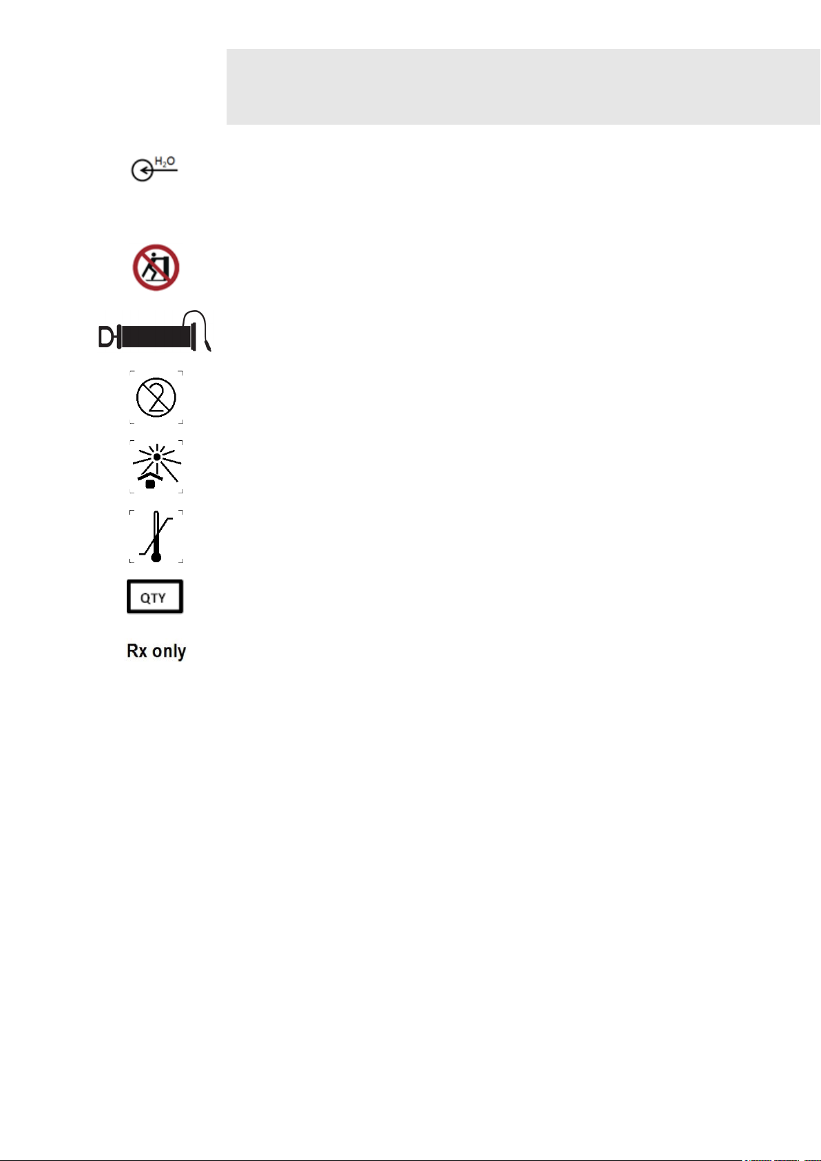
Connection for filling the cooling unit with water (max.1.5L)
The device must not be tilted.
Pump symbol indicating the location of the pump for water evacuation.
Do not reuse. If used more than once, cross infection may occur.
The transport package shall not be exposed to sunlight.
Symbol to indicate the maximum and minimum temperature limits at which the
item shall be stored, transported and used.
Quantity
Federal law restricts this device to sale by or on the order of a (licensed
healthcare practitioner
Max. 1.5L

Contents
Illustrations
Front of the Device
Rear of the Device
Screens / Displays
Explanation of Symbols
Page
1.
Intended Purpose
1
2.
Side Effects 2
3.
Application Information
3
4.
Warnings 4
5.
Device Setup 5
6.
Self-Test 6
7.
Basic Settings 7
8.
Operation Instructions 10
9.
Technical Information 12

Contents
10.
Cleaning / Disinfection 13
11.
Scope of Delivery and Accessories 14
12.
Device Combinations 15
13.
Safety and Maintenance 16
14.
Setup Water cooling Circuit 17
15.
Error Messages Troubleshooting Disposal 21
16.
Manufacturer´s EMC declaration 25
Valid for ZWave Q devices.
This instructions for use is an integral part of the device. It must be stored with the device and kept accessible
at all times for anyone authorized to operate this device.
Information as of June 2019

Intended Purpose
1
Page 1
Intended Use
ZWaveQ is a device for the external application of radial sound waves to
relieve minor muscle aches and pain, for the temporary increase in local
blood circulation and temporary reduction in the appearance of cellulite.
Treatment Patient
Population
a) Age: Only adults,
No teenagers, children, or infants
b) Gender: no restriction
c) Ethnic group: no restriction
d) Skin color: no restriction
e) Conditions for health: The patient must be able to sense heat and
communicate pain.
User Group
a) Restricted to personnel that can operate FDA Class 1 device.
b) Knowledge of the working principle of the shockwave therapy devices
is highly recommended.
Application Principle
Application duration
Radial Pules Therapy typically can last up to 30 minutes
Contraindications
Vascular disorders at or in the vicinity of the treatment area
Open wounds at or in the vicinity of the treatment area
Local infections in the treatment area
Application in the area of malignant / benign tumors
Application directly on cartilage surfaces or in the area of the small facet joints
of the spine
Applications directly over implanted electronic devices, such as a pacemaker,
pain pump etc.
In areas where mechanical energy in the form of vibration could results in
damage to tissue, e.g. metal implants
Following a fracture, in cases of muscle fibre tears or muscle tears
In general, we advise
against treatments
If blood clotting disorders are present or the patient is receiving treatment that
results in a change in the blood clotting behaviour
During pregnancy
On patients with neurological diseases resulting in impairment of the
vasomotoric function in the treatment area
Over air-filled cavities such as treatment on the thoracic spine, etc.
On children, particularly around the epiphyseal plates
Care is required for
patients
with impaired sensitivity
with severe autonomic disorders
under the influence of drugs and/or alcohol
as circulatory stresses and inadequate treatment responses cannot be
excluded

Side Effects
2
Page 2
Treatments with ZWaveQ can occasionally lead to dermatitis, petechiae,
haematoma, swelling or pain.

Application Information
3
Page 3
Attention!
Before using the device on a patient, the user is must be familiar with the instructions
for use and individual treatment methods as well as the intended use /
contraindications, warnings and application information. Additional sources of
information about types of therapy should be consulted.
Attention!
Before use, ensure that the device is powered via a properly grounded plug with a
grounded outlet. The device must only be operated with the supplied power cord.
The power cord must be protected against mechanical stress.
Attention!
Magnetic and electrical fields can affect the function of the device. For this reason,
do not operate ZWaveQ in the vicinity of devices which generate strong
electromagnetic fields (X-ray or diathermy equipment, MRI machines and Radio
Frequency devices). Please keep a safe distance of at least ten feet.
Attention
!
ZWave
Q
is not suitable for use in areas with an explosive, flammable or combustive
atmosphere.
Attention!
Do not place the device adjacent to heat sources (heating, hot mud products, sauna
etc.), and leave a gap of at least 20 inches between the device and a wall (to allow
for adequate ventilation and cooling).
Attention!
During use, the device is to be located in a position allowing direct access to the
device´s central main supply so that it can be disconnected from the main supply at
any time.
Attention
!
Only accessories provided by Zimmer MedizinSysteme GmbH must be used.
Attention
!
The silicon protection cap (15mm) for the handpiece H2O Slim is only for single use.
Attention
!
The silicon protection cap (39mm) for the handpiece H
2
O Aesthetic should be
carefully cleansed and disinfected between each patient.
Attention
!
These instructions for use should always be kept with the device at all times in order
to give access to the persons responsible for the operation of the device.
Attention
!
No changes may be made to the device during the product’s life unless specifically
recommended by the manufacturer.
Attention
!
The complete medical device is suitable for use in the patient environment.
Attention
!
To disconnect the device from the power supply, disconnect the main plug from the
socket.

Warnings
4
Page 4
Users of the device must be instructed in the correct use of the system and have
appropriate skills.
Treatment instructions concerning the place of treatment, duration and extent of
treatment require medical knowledge and may only be given by licensed physicians,
therapists and health professionals. These instructions are mandatory.
During therapy, the user must be able to hear to the patient's feedback.
Use in wet areas is inadmissible and, if disregarded, may result in significant
damage and endanger both the patient and the user.
Do not push the sides of the device that are marked with the warning symbol. Do not
lean on the device.
The silicone protection cap (39mm) for the Aesthetic handpiece must be inspected
for wear and tear after each treatment.
Simultaneous connection of the patient to a high-frequency surgical device is not
permitted. This can lead to burns.
The use of the device outside the settings or applications specified in the instructions
for use may lead to hazards resulting in the uncontrolled release of laser energy.
No maintenance work may be carried out during radial pulsed therapy.
Inspect the device before use. If there is any damage, it must not be used.
To avoid the risk of electric shock; the device´s main plug must be disconnected
from the mains supply before performing any maintenance or cleaning activities.
Dispose packaging materials properly. Make sure that is not accessible to children.

Device Setup
5
Page 5
Note:
Make sure that the power switch on the device is set to "0".
Mains cable
connection
Connect the power cable to the appropriate socket on the device and
connect the cable to the mains.
Note:
The device may only be connected to power outlets with grounding
contact.
Handpiece
connection
Connect the handpiece to the socket on the rear of the SysCart.
Footswitch
connection
Connect the footswitch to the socket and place it on the floor.
Switch on the device
Switch on the device with the main switch on the lower left front of the
monitor.
Filling the water
circuit
See Chapter 14
Switch off the device
The unit is switched off via the main switch (6). To disconnect the unit
completely (all-pole) from the mains supply, the power cord has to be
removed.
Attention
!
All cables must be protected from any mechanical damage.
Attention!
After horizontal transport or assembly, the device must stand upright for
at least 30 minutes prior to being switched on. The compressor might
otherwise be damaged.
Note:
The user is responsible for the use of the device. The device may not be
modified without the consent of the manufacturer. The party combining
the device and thus operating a medical system is independently
responsible for combining the devices correctly.

Self-Test
6
Page 6
Self-Test
After the device is switched on, the ZWaveQ performs a self-test, which checks all
internal components.
In the event of a fault, an error message appears.
In addition, an extended function test can be performed as described below.
This test should be performed monthly or if there are any doubts about the viability of
the device.
Note:
Before performing the functional test, ensure that the handpiece and foot switch are
connected properly to the device.
Check to see whether the power cable is connected properly to the device and
whether it is connected to the network.
Start Screen
From the Start Screen you get to the foolowing settings

Basic Settings
7
Page 7
Setting Screen
Note:
Changes in the basic settings are only possible from the start-up screen
Settings menu
Via the Start Screen you get into the settings menu (general), the factory settings can
be individually changed and adjusted
The setting options are described below.
The default settings are pre-programmed as shown in the screen.
(1) Start Settings
Individual options of the start menu.
(2) Language
Choose language. The selection is made directly in the corresponding line.
(3) Welcome Text
Activation of the “Welcome text” field opens a window with an alphanumeric keyboard
for entering a welcome message on the start-up screen.
Activation of the button with the green arrow saves the entered text.
Activation of the button with the red cross takes you back to the configuration menu.
(4) Volume
Option to adjust the volume of the signal tones when activating the control panels.
The volume is adjusted via the two arrow keys.
(5) Brightness
Option to adjust the brightness of the screen. The brightness is adjusted via the two
arrow keys.
(6) Maintenance
Leads to the “maintenance” screen, see following section.
(7) Version
Activation of the “Version” button opens a window with information about the current
software version.
(8) Load Default
Activation of the “Load default” button restores the default factory settings.
1
2
3 4
5
6
7
8
10
9

Basic Settings
7
Page 8
(9) Colour Scheme
Activation of the “Colour scheme” button changes the display colour from dark to
bright and vice versa.
(10) Handpiece
In this display panel, the counter status for the connected handpiece is illustrated.
By touching the button with the green arrow in the right bottom of the display the
settings are saved and the configuration menu is closed
Maintenance
Screen
(1) Handpiece
detection
The information about the connected handpiece is shown in this display.
(2) Footswitch
The information about the connected footswitch is shown in this display.
(3) Water cooling
circuit
Gives the user the possibility to empty and fill the water cooling circuit.
(4) Pulse Counter
Here the user can activate / stop the pulse counter.
(5) Disconnect the
handpiece
This gives the user the opportunity to disconnect the handpiece. The device pumps
out the water of the handpiece so it can be disconnected by the user.
(6) Test Handpiece
Pressing this button, a test is performed to check if the handpiece is connected and
working properly.
By touching the button with the green arrow in the right bottom of the display the
settings are saved and the configuration menu is closed.
1
2
3
4
5
6

Basic Settings
7
Page 9
Protocol
Screen
(1) Energy
Displays the set pulse energy. When the application is active, the bar graph is filled in.
The pulse energy can be set before and during the delivery of pulses. The pulse
energy is adjustable between 60–185 mJ in 10 mJ steps.
(2) Frequency
(3) Handpiece
Displays the set frequency.
Frequency range: 1–22 Hz, adjustable via the right Encoder. The maximum selectable
frequency depends on the energy level selected.
Connection of handpiece.
(4) Mode
Displays the selected operating mode. When activating the “mode” window, the
selection menu appears with the operating modes:
Series pulses, burst 4 pulses, burst 8 pulses, burst 12 pulses.
The desired mode of operation is selected directly in the corresponding row.
(5) Number of
pulses
Display of the preselected number of pulses and the currently emitted pulses as well
as the total number of emitted pulses if the total number of emitted pulses is not pre-
selected. Display of the counting direction in ascending or descending order.
Activation of the “preselection” field will open the input menu for entering a
preselected number of pulses. The pre-selection can be done in 100 or 1000 steps.
(6) Counting
direction
Activation of the button determines the counting direction (ascending or descending)
of the number of pulses delivered.
(7) Reset
(8) Save
Resets to 0 in the case of ascending counting order and to the pre-set number of
pulses in the case of descending counting order.
Activation of the button opens the field for entering an individual program for storage
in the favorites list.
(9) Title bar
Display of the current program name and the selected handpiece.
9
2
3
4
5
6
7
8
1
Table of contents