Zipp Manufacturing Illusion Instruction Manual

Table of Contents
Introduction 1
S E C T I O N 1 - T H E F R A M E
Supplies needed to build 3
Equipment needed to run 4
Building Surface 4
Parts identification 5
Building Jig 8
Bulkheads 8
Fuselage Sides 9
Chines 10
S E C T I O N 2 - S H E E T I N G
Tunnel Top 10
Side Sheeting 12
Bottom Sheeting 13
Transom Assembly 16
Sealing interior 18
Deck Sheeting 19
Cowling 22
Cowl Mounting 25
SECTION 3- EQUIPMENT
Radio Box 14
Servo Installation 29
Engine Mounting 32
Setup Board 32
Fuel Tank 36
S E C T I O N 4 - P A I N T
Hull prep 37
Sanding and Filling 37
Primer and Paint 38
S E C T I O N 5 - A S S E M B L Y
Final Assembly 38
Setup 39
Balance 39
S E C T I O N 6 - R U N N I N G
Running 40
A L S O S E E :
Tuning Tools
Troubleshooting
Lawless Drilling Template

I L L U S I O N
1
Introduction
Thank you for purchasing this kit. We are sure that it will
provide you with many hours of enjoyment.
Please take the time to read this entire manual before building this
boat. You will become familiar with the building order, and less likely
to make mistakes.
This kit is not a toy. Although R/C boating is a fun and rewarding hobby, it can be
dangerous if not done with common sense and safety in mind. Just about anyone
should be able to build this kit, but it should not be operated by children without close
adult supervision.
Here are a few safety tips:
Never operate your boat alone. If you get hurt, you may not be able to
drive for help.
Never, ever operate your boat in an area where there are full size boats
or swimmers. If something happens, a 15 pound object traveling at 50+
mph can do serious damage.
Always use a failsafe. This shuts the engine off in the event of radio
signal loss. Test the failsafe each day of running, by shutting off your
transmitter.
Always carry a fire extinguisher, as gasoline is extremely flammable.
The manufacturer assumes no liability for damages or other loss in the use of
this product, as we have no control over the construction or end use of this
product.

I L L U S I O N
2
Purpose
This boat was created as a race boat, designed for the Gasoline outboard
tunnel class.
The boat is currently legal in all Gas Tunnel classes.
The Illusion was designed specifically for the Lawless®“G” Drive, and a
Zenoah® Gasoline engine.
It has not been tested with any other drives or engines.
Note:
Some images have been
removed for this PDF web
version.
The printed manual supplied with
the kit is complete.

I L L U S I O N
3
Tools and supplies needed to build:
Small wood plane (mini plane)
Sanding blocks with 80 and 220 grit paper
Drill with bits
Square
12x48 FLAT plywood or bench (the thicker the better)
Thin and Medium CA glue and accelerator
Good quality 30 minute epoxy
Epoxy finishing resin or West Systems Epoxy
Screws or nails
Lots of clamps! Spring clamps, paper clamps, c clamps, etc.
Weights. Bricks, etc.
Razor saw
Wood filler
Primer
Paint

I L L U S I O N
4
Additional items needed to complete:
Zenoah Gasoline engine
Lawless “G” Drive outboard drive unit
Tuned pipe or canister muffler (check the rules)
2 channel surface radio with 1 standard and 2 heavy duty servos (300 in/oz minimum
each)
Throttle pushrod
Steering pushrod (at least “4-40” size with carbon of fiberglass tubes)
3 pushrod seals (Zipp #3404 )
16-24 ounce fuel tank or IV bag and tubing (gasoline compatible)
Zipp 470 prop (starting point)
Cable grease (Aeromarine # 7145 )
2 feet large silicone tubing (water line)
Before we can start building, we need to do some prep work. Good prep work
will pay off later with a straight, true running boat.
First, we need a flat work surface. Nothing else will do.
If you don’t have a perfectly flat bench, you can make one with your piece of
12x48 plywood.
Simply screw a couple of 2x4’s lengthwise to the bottom. Make sure the 2x4’s
are straight!
You can then put this on a bench, and shim the corners to make it steady.
Or, if you are really pressed for space, you can set it on a couple of saw
horses.

I L L U S I O N
5
The Build
We are ready to start the build!
Remember- The boat is being built upside down. Any reference to the top or
bottom refers to the boat’s top or bottom. If you are going to attach something
to the top, it would be closest to the bench. Right and left are always as you
are sitting in the boat, or from the rear.
Got it? If not, stand on your head as you build…
Let’s identify the parts in the sheets. Don’t remove the parts until you actually
need them, as some look similar, but are not the same.
Before you do anything, carefully sand both sides of each sheet. This makes it
much easier to sand each part later. If any parts fall out of the sheets, tape
them back in place.

I L L U S I O N
6
Take the time to mark all the parts, as there are a few parts that are similar,
but not the same.

I L L U S I O N
7
We like the Great Planes 11 inch bar sanders
Use good quality epoxy and finishing resin
Your life will be much easier with one of these
Acid brush trimmed for fast epoxy application

I L L U S I O N
8
Stringers and half-bulkheads being glued.
Note that the sponson sides are mirror images.
Sponson insides and all bulkheads in place on jig.
Let’s get started.
Attach the jig board to your FLAT bench (or 12x48
ply) with screws, nails, clamps or whatever you
need, to make sure it’s attached to the surface.
Make sure the “F” is so that you can read it.
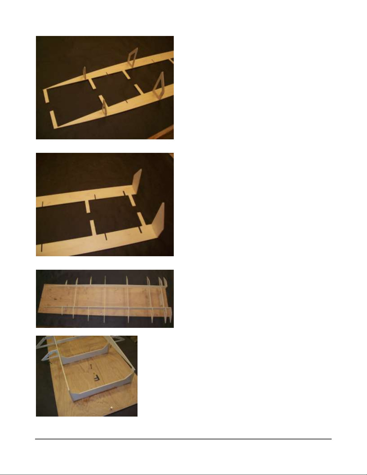
Remove bulkheads R, 4, 6 and the (2) sponson
sides.
Sand the edges with 80 grit to remove the fuzz, as
well as the little tabs that held them in the sheet.
Lay each sponson side on your bench so that they
are mirror images of each other.
Test fit the half bulkheads R, 4 and 6 into the sides.
Be sure that you understand which is the bottom of
the sponson sides and bulkheads. Put pieces of
waxed paper under the areas you are gluing so that
you don’t attach the parts to the bench.
If all is well, glue the half bulkheads in place with
medium CA and accelerator.
Use a square to be sure that all bulkheads are 90
degrees to the side.
Remove all remaining bulkheads from their sheets,
and sand the edges smooth as before. Make sure
all parts are marked before you remove them.
Assemble the bulkheads into the slots in the sides,
including the ¼ inch transom bulkhead. Be sure that
all are in the correct slot. Don’t glue anything yet.
Put this whole contraption on the jig, and carefully
insert each tab into its jig slot.
You can use a small hammer to tap each bulkhead
to be sure it is seated.
Don’t let the tabs extend below the jig, but make
sure that all tabs are fully inserted.
Once you are happy with the way everything goes
together, start gluing the tabs into the jig.
Tap each tab to be sure it is fully seated.
Remove and sand the jig supports, and glue them
to the jig at bulkheads 6 and the nose. The
supports glue into slots in the jig.
Using thin CA and accelerator, glue the bulkheads
to the sponson insides. Don’t glue the ¼ inch
transom yet. Be sure that all bulkheads are flush
top and bottom, and fully inserted in their slots.
Try to keep everything as straight and square as
possible.

I L L U S I O N
9
Fuselage sides being installed in framework.
Rear radio box mounts.
Note blind nuts glued to bottom of mount.
When done, check to make sure everything is flat,
flush and square, and then reglue all joints with thin
CA.
Fuselage sides
Remove and sand the two fuselage sides, and
carefully slip them up into the bulkheads from the
bottom.
You will have to lay them into position, and “rock”
them into place.
The fuselage sides start at the transom and go to
bulkhead 7. Do not glue in place yet.
Locate the two radio box mounts with holes in them.
Glue the two mounts together, aligning the holes.
Glue the two 6-32 blind nuts into the assembled
mount. The blind nuts go in the part of the mount
without tabs. Use the 6-32 screws and washers to
draw them into place. Use medium CA to fix them in
place.

I L L U S I O N
10
Radio box mounts installed.
Tunnel bottom being glued into place.
Side chine in place. Payclose attention to how the
chine fits at the nose
Glue in the front and rear radio box mounts.
These go into slots in the sides as they are
assembled. The radio box mount with the blind
nuts goes in the rear, with the blind nuts facing up.
Slide one side (at the front) out of place and insert
the radio box mounts. While holding the mounts in
place, slide the side back up.
Glue the fuselage sides to the framework, the RB
mounts and the transom to the fuselage sides with
30 minute epoxy. Glue the transom to the
framework at this time as well.
Coat the tops of the mounts with epoxy, as this area
will be difficult to seal once the tunnel top is in
place.
Tunnel Top
Once all the frame work is glued, we can move on
to the tunnel top.
Remove the tunnel top sheet and sand the edges
smooth. Test fit this on the center framework,
sanding the framework slightly if it is not flat.
Glue the tunnel top in place with epoxy. Be sure
that it is centered fore and aft. Weight down until
cured.
Side Chines
Remove the side chines from the sheet and lightly
sand. Put these in place on the bulkheads and glue
with thin CA and accelerator.
The front of these chines should be centered on the
sponson inside, and flush with the bottom of the
side (see photos).

I L L U S I O N
11
Side chine flush with the bottom of the sponson
side.
Side chine centered at tip.
Bottom chine in place.
Be sure that the side chine is not hanging down
below bulkhead 6 also.
Use thin CA and accelerator to glue the side chine
in place.
Repeat on the other side.
Bottom Chines
Remove the bottom chines from the sheets and
sand lightly.
Press the bottom chine into the slits in the
bulkheads.
Fit the tab into the slot at the nose of the side chine.
The fit should be tight. You may have to tap this
part in place. Be careful, as the chine is somewhat
fragile until it is glued in place.
When the bottom chine is fully seated in all slots,
glue with thin CA and accelerator.
Repeat on the other side.
Reglue the chines with thin CA.

I L L U S I O N
12
Bottom chine detail.
Side chine sanded to match angle of bulkheads.
Forward end of sanded chine. Note bevel.
Sponson side sheeting
Plane and sand the side of the framework so that
the side sheeting will sit flat on the framework.
Time to get intimate with your wood plane. If you
don’t have one, stop here. Go to the store and buy
one. Really.
The mistake most people make with wood planes is
trying to take off too much wood.
If you try to plane with the blade too deep, you will
gouge and split the wood.
Adjust your plane to remove about 1/64 of an inch
of material or so.
What we are trying to do with the plane is to shave
the side chine to match the angle of the bulkheads.
When you have it close, use your sanding block
with 80 grit paper to finish.
Dry clamp the side sheeting in place.
Clamp and adjust the sheeting so that it overhangs
an equal amount on the top and bottom. Leave a
little hanging off of bulkhead R as well.
If all Is well, remove the clamps.
Mark the inside of the sheeting.
Using 30 minute epoxy, mix up about 1/2 ounce.
Stir very well.
Using a small stick or acid brush, coat the chines
and bulkhead edges. Work quickly.
Make sure that all surfaces that will touch the
sheeting are coated. Try not to use so much that it
runs all over. Brush epoxy on the front 6 inches or
so of the side, to help strengthen the high stress
nose area.

I L L U S I O N
13
Side sheeting clamped and glued in place.
Bottom sanded and ready for bottom sheeting.
Bottom sheet clamped and weighted.
Start clamping, adjusting the sheeting for equal
overlap on the top and bottom.
Clamp thoroughly, but be careful not to distort the
chines.
Using a new mixing container and applicator, do the
other side.
Allow to cure at least 3 hours. Repeat on other side.
Bottom Sheeting
When the side sheeting is fully cured, plane and
sand the side sheeting even with the bottom of the
bulkheads. Be careful not to change the shape or
angle of the bottom.
When you are satisfied that the side sheeting and
bulkhead bottoms are flush, glue the bottom sheets
on the same way you did the sides, using 30 minute
epoxy.
Use a couple of clamps and some heavy weights to
hold them in place.
Check to make sure that nothing has shifted, then
let it sit for at least 3 hours.

I L L U S I O N
14
Radio box sides being glued.
Radio box sides glued as two assemblies.
Let’s build the radio box while the glue cures on the
hull.
Radio Box
Remove all of the radio box parts: Two long sides,
two short sides, the top and bottom, as well as the
1/8 ply top.
Sand all the parts smooth with 80.
Lay a piece of plastic wrap or waxed paper on your
bench.
Using CA, glue the two small sides to the two long
sides.
The small sides go between the long ones.
Use a square.
Put glue on the edges, and join the two box halves
on the bench.
Lightly sand the bottom of the box.
Glue on the bottom.
Lightly sand the top.
Skip ahead to the section on installing the
servos.
It is much easier to glue in the servo mounts
now, rather than after the radio box top is glued
on.
Once all servo mounts are in place, go to the
next steps.

I L L U S I O N
15
Radio box spacer installed 2 inches from front.
Radio box tongue in place.
Tongue is really a lip…
Draw a line 2 inches from the end of the radio box.
Make sure it’s the end without mounting holes.
Using medium CA, glue the radio box spacer to the
bottom of the radio box, along the line you drew.
Glue the radio box tongue to the spacer with
medium CA. Try not to get any glue under the lip,
as it will interfere with the mounting of the radio box.
The back of the tongue should be flush with the
back of the spacer, and centered side to side.
The tongue is wider than the radio box so that the
front will self center in the hull.
The tongue and spacer serve as the front mount of
the radio box.
The rear is held in place with the two 6-32 screws,
into the blind nuts.

I L L U S I O N
16
Hull trimmed and sanded.
Cutting the hull free of the jig.
Installing transom top and doubler with epoxy.
Back to the boat:
Make sure that it has been at least 3 hours since
you glued the bottom sheeting to the hull.
Trim the excess bottom sheeting flush. You can use
your small plane to get close. Finish with an 80 grit
sanding block.
With your razor saw, cut all the tabs that are holding
your hull to the building jig.
Ditch the jig. We don’t need it any more.
Hey, this is really starting to look like something
now!
After you finish admiring your cool new hull, let’s
move on.
Transom Assembly
Test fit and glue the ¼ inch transom doubler and
the ¼ inch transom top to the front of the transom
with 30 minute epoxy. Use clamps, and check to be
sure it doesn’t slip or slide while it cures.
Try not to get too much glue in the corner, as we
will be gluing transom braces in place next.

I L L U S I O N
17
Side extensions in place.
Transom brace being installed.
Transom braces in place.
When the transom assembly is cured, install the
side extensions with medium CA. Do not use
accelerator. Repeat on other side.
When the transom assembly is cured, install the
transom braces with medium CA. Do not use
accelerator, and glue in one brace at a time.
Glue the second brace right over the first. Repeat
on other side.
Use clamps and make sure they are flush with the
top.

I L L U S I O N
18
Lots of strength here…
Sealing interior with epoxy.
Ready for top deck sheeting.
SealingInterior
Now we need to seal the inside. It is vital that all
exposed wood be sealed.
Mix up about 4 ounces of epoxy finishing resin or
West Systems epoxy. You can thin the resin with
about 10% acetone, so that it brushes easily. Go
easy on the acetone, as it will soften the epoxy glue
joints if you use too much.
It’s pretty funny to get the inside sealed, and see
the side pop off the boat because you thinned the
sealer too much…Don’t ask!
Start from the front.
Using a brush, coat all areas of wood inside the
hull. Get inside the holes.
Continue coating the inside with finishing resin.
If you need to mix more, use a new container and
brush. If you don’t, the old resin will mess with the
new resin, and create a problem. Trust me…
You should also mix a little filler with some epoxy,
and use your finger to create a fillet inside the
center section to bottom joints, to prevent leaks in
this high water pressure area.
After you are 100% sure that all exposed wood
inside the hull has been coated, let it sit overnight.
Table of contents
Other Zipp Manufacturing Toy manuals
Popular Toy manuals by other brands

Bachmann
Bachmann Williams E7A instructions

Fisher-Price
Fisher-Price Fun2Learn Teaching Clock Series manual

Tamiya
Tamiya U.S. BATTLESHIP BB-62 NEW JERSEY quick start guide

Fisher-Price
Fisher-Price Baby Smartronics! Storybook Rhymes manual

Hasbro
Hasbro DISNEY STAR WARS OBI-WAN KENOBI FORCE FX... manual

marklin
marklin Alco PA-1 manual

Fisher-Price
Fisher-Price P7629 instruction sheet

Toys for life
Toys for life SYMETRIX instructions

Fisher-Price
Fisher-Price Kasey the Kinderbot Reading Words &... manual

Mattel
Mattel polly pocket instructions

Star Wars
Star Wars 97815 user manual

Walthers
Walthers CORNERSTONE INTERSTATE FUEL & OIL 933-3006 manual