Zipp Manufacturing Bullitt Thunderboat Instruction Manual

Z I P P M A N U F A C T U R I N G
Bullitt
Thunderboat
Zippkits R/C Boats
BUILDING INSTRUCTIONS
2011 Zipp Manufacturing

Table of Contents
Introduction 1
Purpose 2
S E C T I O N 1 - P R E P A R A T I O N
Tools & Supplies needed to build 3
Equipment needed to run 4
Parts identification 5
Useful Tools 7
S E C T I O N 2 - T H E F R A M E
Turn Fin Doubler 8
Frame Assembly 9
Bottom 13
Putting it all together 13
Engine Rails 15
S E C T I O N 2 - S P O N S O N S
Chine Strips 12
Sponson Non Trips 16
Sponson Bottoms 18
Rear Non Trips 26
Sealing Interior 27
SECTION 3- EQUIPMENT
Radio Box 21
Fuel Tank 29
Running Hardware 34
Engine mounting 30
Shaft and Stuffing Tube 32
Exhaust 37
Deck Installation 42
Cowling 39
S E C T I O N 4 - P A I N T
Hull prep 45
Sanding and Filling 45
Primer and Paint 46
Decals 47
S E C T I O N 5 - A S S E M B L Y
Hardware Assembly 47
Setup 48
Center of gravity 49
S E C T I O N 6 - R U N N I N G
Running 50
Also see:
Troubleshooting
Tuning Notes

B U L L I T T
1
Introduction
Thank you for purchasing this kit. We are sure that it will provide you with many
hours of enjoyment.
Please take the time to read this entire manual before building this boat. You will become familiar
withthe building order, andless likely to make mistakes.
This kit is not a toy. Although R/C boating is a fun and rewarding hobby, it can be dangerous if not done with
common sense and safety in mind. Just about anyone should be able to build this kit, but it should not be operated
by children without close adult supervision.
Here are a few safety tips:
Never operate your boat alone. If you get hurt, you may not be able to drive for help.
Never, ever operate your boat in an area where there are full size boats or swimmers. If something
happens, a 15 pound object traveling at 50+ mph can do serious damage.
Always use a failsafe. This shuts the engine off in the event of radio signal loss. Test the failsafe
each day of running, by shutting off your transmitter.
Always carry a fire extinguisher, as gasoline is extremely flammable.
The manufacturer assumes no liability for damages or other loss in the use of this product, as we have no
control over the construction or end use of this product.

R I V E T T / R O C K E T T
2
Purpose
The Bullitt Thunderboat was designed based on our popular Rivett and Rockett hulls.
Thunderboats are scale type hydros specifically designed for gasoline power.
The Rivett/Rockett were designed as easy to build kits that are also easy to setup, and very predictable
to drive. They have excellent stability and turning ability, and handle rough water very well.
The secret to their outstanding performance is the modern design features, such as the sponson angle
of attack, non trip and deck crown. All these elements add up to an aerodynamically sound design.
The Bullitt adds several new design elements that make the boat more efficient (faster) and easier to
build.
The Bullitt is also legal in all Thunderboat classes in both IMPBA and NAMBA.
You can build this boat without having the engine or radio, but it does make it easier to have them
available when you build.
You can use any gasoline engine, as long as it has mounts for 5 inch rails.
Please note that this boat was designed for the Zenoah style marine engines.
Other engines may not fit without cutting, and may not fit under the cowling.

R I V E T T / R O C K E T T
3
Preparation
Toolsandsuppliesneededtobuild:
Small wood plane (mini plane)
Sanding blocks with 80 and 220 grit paper
Drill with bits
Right angle drill or attachment
Square
FLAT Workbench
3 wood blocks ¾ x 2 x 13 (1x stock or ¾ ply)
3/4x 12x 48 MDF or ply
1 ounce thin CA glue and accelerator
Good quality 30 minute epoxy
Epoxy finishing resin
Lots of clamps! Spring clamps, paper clamps, c clamps, etc.
Razor saw
Wide tape
Wood filler
Primer
Paint

R I V E T T / R O C K E T T
4
Additional items needed to complete:
Gasoline engine with 5 inch mounts
.250 Collet for engine (Zipp 3440)
.250 36 inch cable w/welded stub shaft (Zipp 3445)
Tuned pipe (Zipp 2011)
2 channel surface radio with 1 standard and 1 heavy duty servo (100 in/oz minimum)
Throttle pushrod (2-56 or 4-40 Size) with Clevises (Zipp 3462 and 3459)
2- 4-40x12 Pushrods (Zipp 3463)
¼” OD carbon pushrod
2 pushrod seals (Zipp 3404 or 3422)
16 ounce Fuel Tank or IV Bag(gasoline compatible)
.250 strut (Zipp 3416)
.250 drive dog (Zipp 3442 or 3448)
6518/3 or 6717/3 prop (Zipp 4003)
Prop nuts (Zipp 3450)
Engine Mounts (Zipp 3409 for Zenoah)
Cable grease
Large rudder (water pickup type) (Zipp 3413)
5 feet large silicone tubing (water line) (Zipp 3461)
12 inch length of 11/32 brass tubing (Zipp 3453)
36 inch length of 5/16 brass tubing (Zipp 3452)
Floatation (pool noodles, foam, etc.)
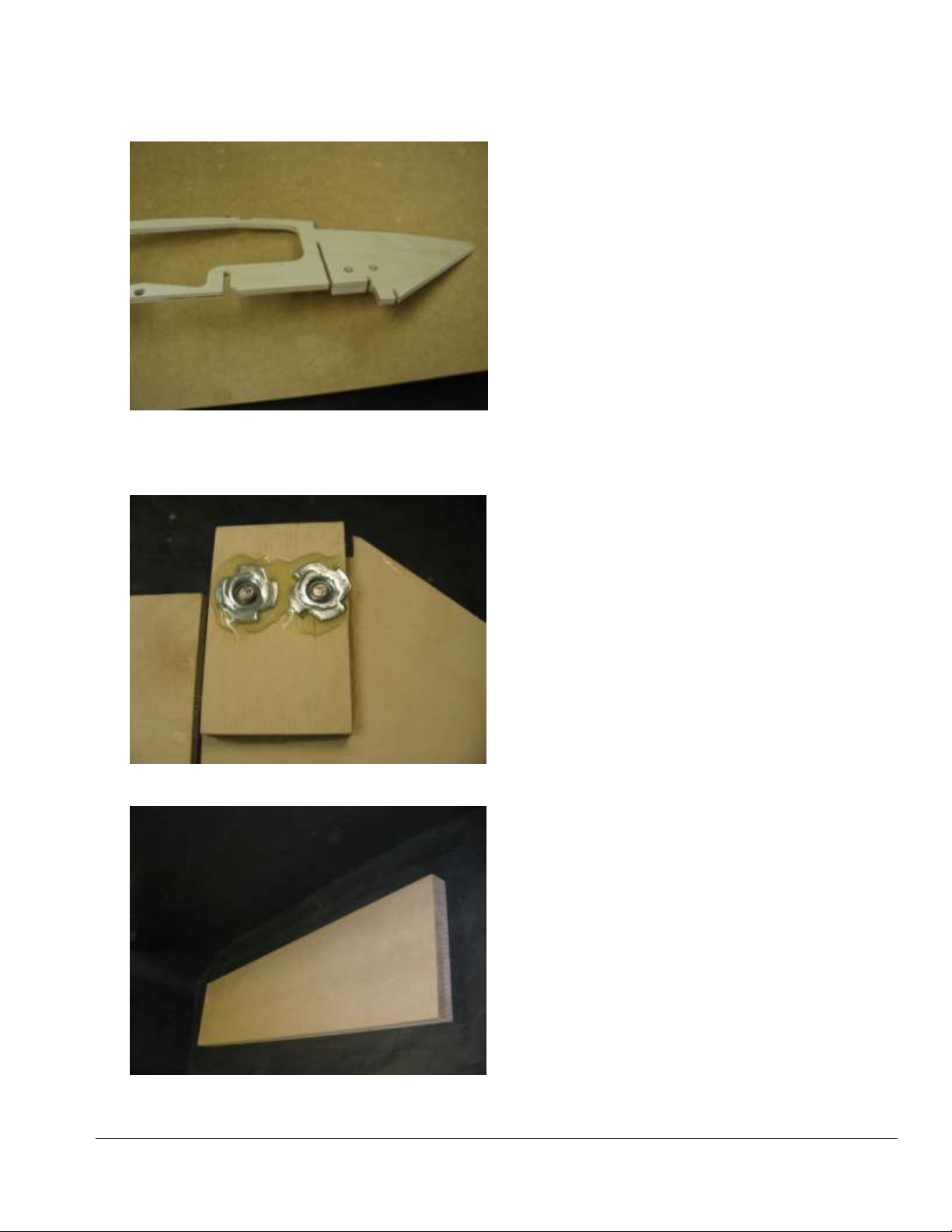
Before we can start building, we need to do some prep work. Good prep work will pay off later
with a straight, true running boat.

R I V E T T / R O C K E T T
5
First, we need a flat work surface. Nothing else will do.
Put your 3/4x13x48 MDF or plywood on the bench. If necessary, screw it down so that it stays flat.
The entire boat will be built on this, so make it right.
We are ready to start the build!
Let’s identify the parts in the sheets. Don’t remove the parts until you actually need them, as some look
similar, but are not the same. This boat is not symmetrical. The right and left are not the same, so it
is critical that you mark the parts correctly, or they will not fit. Note that all reference to right or left are
as if you were sitting in the boat.

R I V E T T / R O C K E T T
6
`
We like the Great Planes 11 inch bar sanders
Use good quality epoxy andfinishing
resin
Your life will be much easier with one of these
Epoxy brush trimmed for fast epoxyapplication

R I V E T T / R O C K E T T
7
Marking parts before removal.
Bulkhead 3 with turn fin doubler in place.
Doubler installation. Note bottom chine slot is
not covered.
Let’s get started
The first thing you should do is to
carefully sand the parts while they are
still in the sheets. Do this with your 80
grit sanding block.
Sand both sides, as this will make it
much easier to sand the parts once they
are out of the sheet.
While the parts are still in their sheets,
use a pencil to mark each part with the
name. Note that the parts only fit
correctly one way.
Turn fin doubler
Sand the edges of bulkhead 3. Sand
inside the holes.
Remove the cutout containing the turn
fin doubler.
Remove and sand the doubler. Toss the
piece it was in.
The doubler only goes on correctly one
way.
Hold the doubler over the matching
holes on bulkhead 3. Make sure you are
on the FRONT RIGHT of the bulkhead.
This will be the forward facing side.

R I V E T T / R O C K E T T
8
Correctly installed doubler. Holes centered
and slot uncovered
Blind nuts epoxied to turn fin doubler.
Our buildingboard is two pieces of 3/4x13x48
MDF Covered with wax paper.
Make sure the doubler will be on the
front (inside) of the bulkhead.
When you are sure you have it correct,
glue the doubler to the bulkhead with 30
minute epoxy. Clamp while it cures.
The doubler will be on the right front
(inside) of the bulkhead when correctly
assembled.
Install the two blind nuts to the turn fin
doubler with 30 minute epoxy.
Frame assembly
Cover your building board with waxed
paper or clear plastic wrap. We don’t
want to glue the boat to the building
board…

R I V E T T / R O C K E T T
9
Fitting bulkheads to stringers before wicking
thin CA into joints.
Be positive that bulkheads are in correctly before
gluing!
Note that air vents are on the leftside.
Start by assembling bulkheads 1, 2 and
3 to the side stringers. Make sure the
bulkheads are in the correct slots, and
facing the correct way. The “R” should be
on the right.
Push the bulkheads all the way into the
stringers, until they are flush at the
bottom of the stringer. You may need to
tap the bulkheads with a block of wood
or a small hammer to get them fully
seated.
Be sure that the cooling slots in the side
stringers are on the left side when viewed
from the rear.
Once you are satisfied with the fit of the
bulkheads in the stringers, wick some
thin CA into the joints. Don’t glue
bulkhead 3 until the others are done.
Don’t use so much CA that it drips off
the part. Thin CA is about as thick as
alcohol, so it runs and seeps everywhere.
Hit each joint with accelerator to harden
it. Only glue once, we will go
over the joints a second time after we fit
this assembly to the bottom. If
needed, we can break the glue joints
pretty easily at this point, but not after
double gluing.
Now glue bulkhead 3, being careful to
align the bottom part flush with stringer.
Also be sure the fin doubler is on the
right.
Fit bulkheads 4 and 5, making sure that
they fit tightly to the side stringers. The
two holes go on the right. Wrap a rubber
band around bulkhead 5 to keep it in the
stringers.
Set this assembly aside for now.

R I V E T T / R O C K E T T
10
Bottom sheets taped together.
Bottom curing.
Gusset glued to bulkhead 6.
Bottom
Place the bottom sheets on the building
board. Align the sheets at the rear. Don’t
worry if the front isn’t perfectly aligned.
Check the fit of the two sheets and sand
the edges if needed.
Tightly tape the bottom sheets together
with masking tape. Tape only one side.
Mix up some 30 minute epoxy and glue
the sheets together by “hinging” them
open and applying epoxy.
Close the gap, wipe away any excess
epoxy and tape tightly closed.
Allow to cure.
Note that the completed bottom has a right
and left. The right side is wider. If you have
trouble figuring this out, slip the bottom in
place on the framework. You will see that
it only fits the framework correctly one
way.
Check the fit of the transom gusset into
the bottom. Make sure it fits tightly to the
bottom. Also check the fit of the gusset
into bulkhead 6.
Once you have identified the correct
orientation of the bottom, glue bulkhead 6
to the bottom.

R I V E T T / R O C K E T T
11
Bulkhead 6 being glued in place with gusset
installed.
Inner chine in place.
Inner and outer chines in place.
Clamp a piece of wood to the rear of
bulkhead 6 to keep it straight if needed,
and then glue it and the gusset to the
bottom with epoxy.
Be sure the back of the bulkhead is flush
with the back edge of the bottom.
Chines
Gather the inner chines and sand the
edges smooth.
The chine for the right side has two holes
in it.
Slip the inner chines in place from the
bottom. Check to see that the bottom is
flush with the bulkheads.
Install the outer chines, be sure they are
flush with the bottom of the bulkheads
and.
Wick thin CA in the joints and hit with
accelerator.

R I V E T T / R O C K E T T
12
Bottom glued to sides. Note broken cinder
blocks as weights.
Bottom doubler in place3/8 inch back from
nose.
Bulkhead 6 and gussets glued in place.
Putting it together
Slip the framework over the bottom.
Place weights on the bottom to keep it
flat against the building board.
Align the bottom with the rear of bulkhead
3. Check both sides.
Using epoxy, glue the bottom to bulkheads
3, 4 and 5. This area of the bottom is flat.
Do not glue bulkhead 1 to the bottom yet!
Glue bulkheads 2 and 3 to the bottom.
Wrap your 3/4x2x13 gluing block with
waxed paper. Slip it under bulkhead 2 to
support the bottom while we glue
Press down on bulkhead 2 and if it is
tight to the bottom, wick thin CA into the
joint, and spray with accelerator.
Do not glue the center area of bulkhead
2, as it will be removed later.
Slide the gluing block forward to
bulkhead 1.
Mark 3/8 inch back from the front edge
of the bottom on both sides. Glue the
forward bottom doubler in place using
these marks as a guide.
Also use the center notch in this doubler
to keep it centered.
Now glue the bottom to the sides only in
the area of bulkhead 1! Do not glue
bulkhead 1 to the bottom yet!
.Epoxy bulkhead 6 to the side stringers.
Be sure bulkhead is 90 degrees to the
bottom. Side stringers may overhang
bulkhead slightly. We will trim these
later. Glue in the two gussets between
the side stringers and bulkhead 6.
Allow to cure

R I V E T T / R O C K E T T
13
Outer non trip chines are glued to both inner
and outer chines.
Bulkhead 3 must be 90 degrees.
Cutting out the middle of bulkhead 2.
Install the outer non trip chines. Note
that the right chine has two holes in it.
The outer non trip chines get glued to
the tops of both inner and outer chines.
Use a square to be sure that the rear of
bulkhead 3 is perfectly square. Repeat
on the other side and glue with thin CA.
This is a critical step as the turn fin bolts
here.
Double glue all bulkheads and chines to
the bottom and sides, except bulkhead 1.
Do not glue bulkhead 1 to the bottom yet!
Use your slitting saw or razor saw to cut
the center out of bulkhead 2.
Leave the top bridge in place for now, as
it keeps the sponsons from twisting until
we can put the deck on.
Lightly sand the cut area so that it is
straight and smooth, as the engine rails
will be glued here.

R I V E T T / R O C K E T T
14
Fitting engine rails. Note front holes and
notch in RH rail.
Rails in place.
Make sure the rails are installed correctly!
Engine Rails
Lightly sand the 2 engine rails.
The engine rails have round holes to
indicate the front. The right rail also
has a cutout for the carb.
Test fit the rails as follows:
Put the right rail in the slot in bulkhead
3.
Push the rail against bulkhead 1 so that it
“bows” forward slightly. The rail will snap
into place. Do the same for the left rail. If
all looks good, carefully remove the rails
by bowing bulkhead 1 back so that you
can get them out, one at a time.
Mix up about ½ ounce of 30 minute
epoxy.
Coat the bottoms of the rails, as well as
the slots in the bulkheads with epoxy.
Coat the drain holes at the rail slots.
Also coat the two vertical surfaces on
bulkhead 2.
Snap the rails in as before. Use any
excess resin to create a fillet where the
rails meet the bottom.
When the rails are fully epoxied in, place
some weights on them, with the gluing
block under bulkhead 2.
Let cure for at least 2 hours.
When cured, press down on bulkhead 1
and double glue in place.

R I V E T T / R O C K E T T
15
Sanding chines for sponson non trip sides.
Ready forsponson side. Note bevel in outer
chine.
Sealing hard to reach areas while gluing.
Rockett hull shown.
Sponson Non Trip
With the hull upside down, use your
wood plane to bevel the side and bottom
chines to match the angle of the
bulkheads.
Sand the chines and bulkheads so that the
non trip sides will fit squarely. Do this in
stages starting from the rear.
Sand from bulkhead 3 to bulkhead 2.
Sand from bulkhead 2 to bulkhead 1.
Sand from bulkhead 1 to the tip.
Note that the outside chine offers very
little surface for the non trip side. This is
normal.
Mix up about ½ ounce of 30 minute
epoxy.
Using your special epoxy brush, put a
coat of epoxy on the chines and
bulkheads where the sides will touch.
Also seal the chines at this time, as they
will be difficult to seal after the sides are
in place.
Brush epoxy on the outer perimeter of
the non trip side.

R I V E T T / R O C K E T T
16
Sponson side with epoxy.
Clamps holding the non trip side in place.
Using the 1/16 overlap gauge to check
the rear overhang..
Place the non trip side on the framework
and adjust it so that it just covers the
(bottom) chine and hangs over 1/16 in
the rear. Use your 1/16 overlap gauge.
Use clamps to hold side against the
frame.
Check that the non trip side is in contact
all the way around.
Double check that everything is still in
place and you have the correct 1/16 inch
overhang in the rear.
Allow to cure at least 2 hours.
Repeat on other side
When the non trip sides have fully
cured, remove the clamps.
Before doing the sponson bottoms, read
ahead so that you understand what we
are trying to accomplish.
Epoxy is hard to remove…

R I V E T T / R O C K E T T
17
Sponson sanded for bottom sheeting .
Forward bottom sanded. Note bevel and inner
chine.
Forward and aft sanded for bottom sheet.
Sponson Bottoms
Plane and sand the sides even with the
sponson bottom. Take your time here,
as this is a critical ride surface.
Note that the bottom is not curved, but
actually two flat, straight running
surfaces. We will refer to these as the
aft bottom and forward bottom.
Also note that the right and left bottoms
are different in width.
Make sure that you sand the sponson
bottom evenly and squarely.
Keep the bottom flat when sanding.
When you reach the front, match the
slope of the inner chine while sanding.
If you have dried epoxy on the inner
chine, and it is preventing the forward
bottom from resting in place at the front,
you can use a single edge razor to
scrape the glue away.
Scraping excess glue with a single edge
razor blade.

R I V E T T / R O C K E T T
18
Aft bottom sheet beveled.
Aft bottom sheet overhang matches non trip side.
Note inside overhang.
Aft sponson bottom sanded to match forward
bottom.
Pre bevel the aft bottom sheets (both
right and left) and carefully sand these
as they will be the finished ride pads.
The bevel should be at one end of the
sheet. Don’t worry too much about
having enough bevel as we will finish
sand this once it is in place.
Make sure that you have the correct
bottom sheet for the side you are
working on ( the wider sheet goes with
the wider bottom).
The sheeting is wider than the sponson
bottom and will overhang both inside
and at the rear.
Use your epoxy brush to coat all areas
that the sponson bottoms will touch.
Do one sponson. This will be bulkheads
2 and 3, as well as the inner chine and
non trip bottom.
Brush epoxy on the outer perimeter of
the bottom. Be sure you do the inside of
the piece (you did mark them as left and
right inside, didn’t you?)
Tape the sponson bottom tightly to the
sponson. Be sure that the inside edge of
the sponson bottom has a 1/16
overhang using your 1/16 tool. Also
make sure that the bottom has the same
1/16 overhang at the rear..
Repeat for the other sponson bottom.
Allow to cure for 2 hours.
Table of contents
Other Zipp Manufacturing Toy manuals
Popular Toy manuals by other brands

Glow Bricks
Glow Bricks Gingerbread House Lego 10267 installation guide

LEGO
LEGO 10665 Juniors Assembly guide

Scorpio
Scorpio Palio pro manual

REVELL
REVELL French Carrier CLEMENCEAU/FOCH Assembly instructions

Airigami
Airigami PAPER AVION SAS SCANDINAVIAN AIRLINES BOEING... manual

Beyblade
Beyblade Driger MS instructions