Zipp RIVETT Instruction Manual

Z I P P M A N U F A C T U R I N G
Zippkits R/C Boats
BUILDING INSTRUCTIONS
2007, 2008 Zipp Manufacturing
750 Ball Road • Frankfort, New York 13340
(866) 922-9477
www.zippkits.com

Table of Contents
Introduction 1
Purpose 2
S E C T I O N 1 - P R E P A R A T I O N
Tools & Supplies needed to build 3
Equipment needed to run 4
Parts identification 5
Useful Tools 7
S E C T I O N 2 - T H E F R A M E
Turn Fin Doubler 8
Frame Assembly 10
Bottom 11
Putting it all together 12
Engine Rails 14
S E C T I O N 2 - S P O N S O N S
Chine Strips 11
Sponson Non Trips 13
Sponson Bottoms 12
Rear Non Trips 17
Sealing Interior 19
S E C T I O N 3 - E Q U I P M E NT
Radio Box 15
Fuel Tank 31
Running Hardware 26
Engine mounting 30
Shaft and Stuffing Tube 30
Exhaust 31
Deck Installation 33
Rivett Deck 43
Rockett Deck 46
Cowling
S E C T I O N 4 - P A I N T
Hull prep 36
Sanding and Filling 36
Cowling 37
Primer and Paint 37
Decals 37
S E C T I O N 5 - A S S E M B L Y
Hardware Assembly 37
Setup 38
Center of gravity
S E C T I O N 6 - R U N N I N G
Running 39
Also see:
Popular Setups
Troubleshooting

R I V E T T / R O C K E T T
1
Introduction
Thank you for purchasing this kit. We are sure that it will
provide you with many hours of enjoyment.
Please take the time to read this entire manual before building this
boat. You will become familiar with the building order, and less likely
to make mistakes.
This kit is not a toy. Although R/C boating is a fun and rewarding hobby, it can be
dangerous if not done with common sense and safety in mind. Just about anyone
should be able to build this kit, but it should not be operated by children without close
adult supervision.
Here are a few safety tips:
Never operate your boat alone. If you get hurt, you may not be able to
drive for help.
Never, ever operate your boat in an area where there are full size boats
or swimmers. If something happens, a 15 pound object traveling at 50+
mph can do serious damage.
Always use a failsafe. This shuts the engine off in the event of radio
signal loss. Test the failsafe each day of running, by shutting off your
transmitter.
Always carry a fire extinguisher, as gasoline is extremely flammable.
The manufacturer assumes no liability for damages or other loss in the use of
this product, as we have no control over the construction or end use of this
product.

R I V E T T / R O C K E T T
2
Purpose
The Rivett and Rockett were designed to fill a void in the gas boat market.
There simply was not a scale type hydro specifically designed for gasoline
power.
The Rivett and Rockett were designed from the ground up as gas boats.
They were literally designed around a Zenoah marine engine!
They were designed as easy to build kits that are also easy to setup, and very
predictable to drive. They have excellent stability and turning ability, and
handle rough water as well as any hydro.
The secret to their outstanding performance is the modern design features,
such as the sponson angle of attack, non trip and deck crown. All these
elements add up to an aerodynamically sound design.
You can build this boat without having the engine or radio, but it does make it
easier to have them available when you build.
You can use any gasoline engine, as long as it has mounts for 5 inch rails.
If you use a Zenoah or similar, you will generally use a collet type of cable
system.
If you use a Homelite, or similar sport engine, you will generally use a square
drive type.
Please note that this boat was designed for the Zenoah style marine engines.
Other engines may not fit without cutting, and may not fit under the cowling.
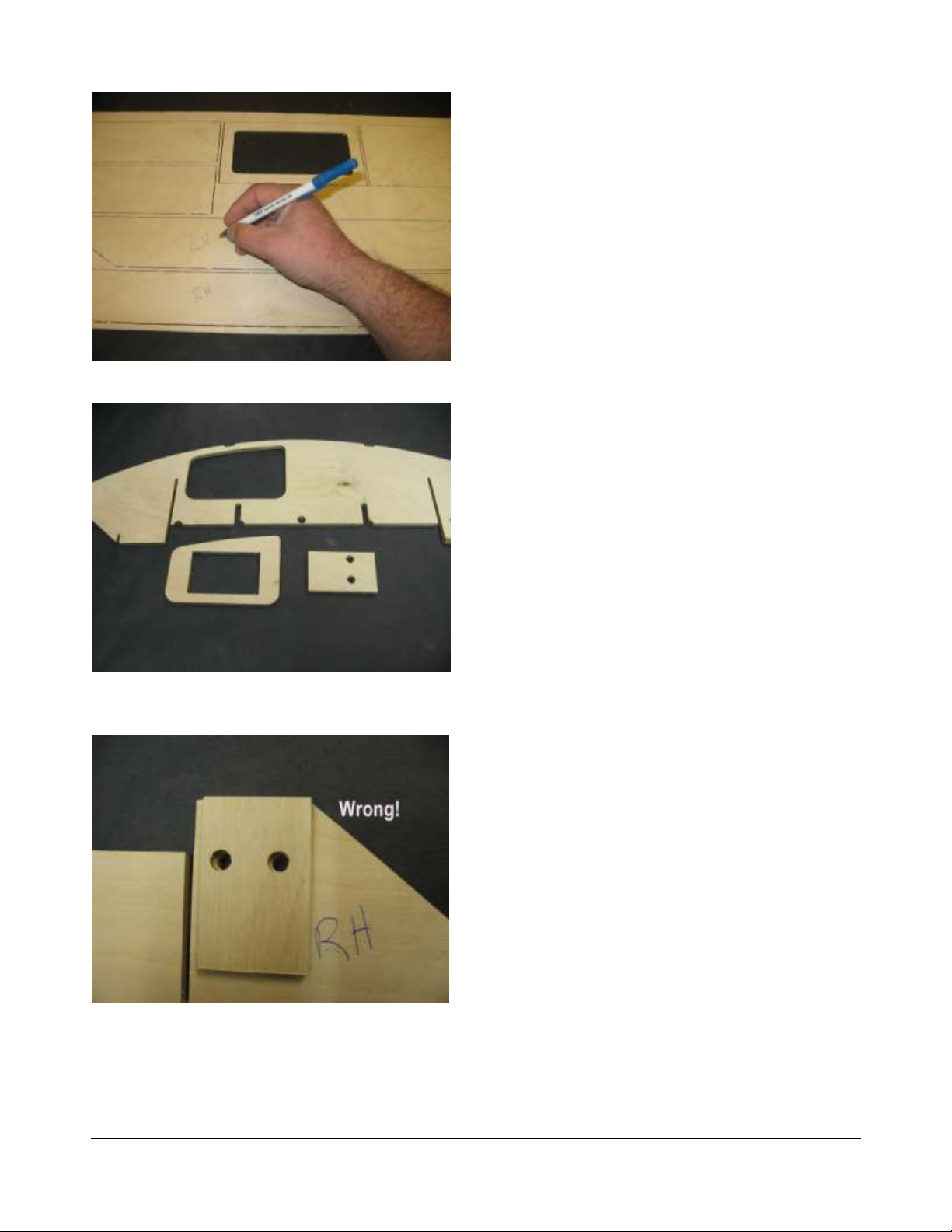
These kits are identical, except for the top decks. Construction is identical,
except for the top decks. Both the Rivett and Rockett are built exactly the same
way, and we show both decks.
This reduces our costs, as we only have to produce one manual for both kits.
You benefit because this keeps the kit price reasonable.

R I V E T T / R O C K E T T
3
Preparation
Toolsandsuppliesneededtobuild:
Small wood plane (mini plane)
Sanding blocks with 80 and 220 grit paper
Drill with bits
Right angle drill or attachment
Square
FLAT Workbench
3 wood blocks ¾ x 2 x 10 (1x stock or ¾ ply)
3/4x 10x 48 MDF or ply
1 ounce Thin CA glue and accelerator
Good quality 30 minute epoxy
Epoxy finishing resin
Lots of clamps! Spring clamps, paper clamps, c clamps, etc.
Razor saw
Wide tape
Wood filler
Primer
Paint

R I V E T T / R O C K E T T
4
Additional items needed to complete:
Gasoline engine with 5 inch mounts
.250 Collet for engine (Zenoah type engines)
.250 30 inch cable w/welded stub shaft (Zenoah type engines)
.250-.250 brass ferrule (sport “trimmer” type engine)
30 inch section of square drive cable (“trimmer” type engine- get from trimmer)
¼ inch stub shaft (“trimmer” type engine)
¼ inch thrust bearing (“trimmer” type engine)
Tuned pipe
2 channel surface radio with 1 standard and 1 heavy duty servo (100 in/oz minimum)
Throttle pushrod (2-56 or 4-40 Size) with Clevises
2- 4-40x12 Pushrods and a ¼” OD carbon pushrod
2 pushrod seals (Zipp 3404)
14 ounce Fuel Tank or IV Bag(gasoline compatible)
.250 strut (Zipp 3403)
.250 drive dog (Zipp 3405)
6518/3 or 6717/3 prop
Prop nuts (Zipp 3450)
Engine Mounts (Zipp 3409 for Zenoah)
Cable grease
Large rudder (water pickup type) (Zipp 3402 or 3413)
5 feet large silicone tubing (water line)
12 inch length of 11/32 brass tubing
36 inch length of 5/16 brass tubing
Floatation (pool noodles, foam, etc.)

R I V E T T / R O C K E T T
5
Before we can start building, we need to do some prep work. Good prep work
will pay off later with a straight, true running boat.
First, we need a flat work surface. Nothing else will do.
Put your 3/4x10x48 MDF or plywood on the bench. If necessary, screw it down
so that it stays flat.
The entire boat will be built on this, so make it right.
The Frame
We are ready to start the build!
Let’s identify the parts in the sheets. Don’t remove the parts until you actually
need them, as some look similar, but are not the same. This boat is not
symmetrical, that is, the right and left are not the same, so it is critical that you
mark the parts correctly, or they will not fit. Note that all reference to right or left
is as if you were sitting in the boat. See back of book for larger pictures,

R I V E T T / R O C K E T T
6

R I V E T T / R O C K E T T
7
We like the Great Planes 11 inch bar sanders
Use good quality epoxy andfinishing resin
Your life will be much easier with one of these
Acid brush trimmed for fast epoxy application

R I V E T T / R O C K E T T
8
Marking parts before removal.
Bulkhead 3 with turn fin doubler removed. Middle
piece gets tossed.
Incorrect doubler installation. Note bottom chine
slot is covered.
Let’s get started.
The first thing you should do is to carefully
sand the parts while they are still in the
sheets. Do this with your 80 grit sanding
block.
Sand both sides, as this will make it much
easier to sand the parts once they are out
of the sheet.
While the parts are still in their sheets, use
a pencil to mark each part with the name,
and which side is right or left, as the parts
only fit correctly one way.
Turnfindoubler
Sand the edgesof bulkhead 3. Sand inside
the holes.
Remove the cutout containing the turn fin
doubler.
Remove and sand the doubler. Toss the
piece it was in.
The doubler only goes on correctly one
way.
Hold the doubler over the matching holes
on bulkhead 3. Make sure you are on the
FRONT RIGHT of the bulkhead. This will be
the forward facing side.

R I V E T T / R O C K E T T
9
Correctly installed doubler. Holes centered and
slot uncovered
Doubler clamped in place.
Be sure the turn fin doubler is glued to the proper
side of bulkhead 3.
Make sure the doubler will be on the front
(inside) of the bulkhead.
When you are sure you have it correct,
glue the doubler to the bulkhead with 30
minute epoxy. Clamp while it cures.
The doubler will be on the right front
(inside) of the bulkhead when correctly
assembled.

R I V E T T / R O C K E T T
10
Blind nuts epoxied to turn fin doubler.
Our buildingboard is two pieces of 3/4x10x48
MDF Cover with wax paper.
Fitting bulkheads to stringers before wicking thin
CA into joints.
Install the two blind nuts to the turn fin
doubler with 30 minute epoxy.
Frameassembly
Cover your building board with waxed
paper or clear plastic wrap. We don’t want
to glue the boat to the building board…
Start by assembling bulkheads 1, 2 and 3
to the side stringers. Make sure the
bulkheads are in the correct slots, and
facing the correct way. The tabs on the
bulkheads are all offset to the right.
Push the bulkheads all the way into the
stringers, until they are flush at the bottom
of the stringer. You may need to tap the
bulkheads with a block of wood or a small
hammer to get them fully seated.

R I V E T T / R O C K E T T
11
Be positive that bulkheads are in correctly before
gluing!
Note that air vents are on the left side.
Bulkhead 6 and transom gusset glued to bottom.
Once you are satisfied with the fit of the
bulkheads in the stringers, wick some thin
CA into the joints. Don’t glue bulkhead 3
until the others are done.
Don’t use so much CA that it drips off the
part. Thin CA is about as thick as alcohol,
so it runs and seeps everywhere.
Hit each joint with accelerator to harden it.
Only glue once, we will go over the joints a
second time after we fit this assembly to
the bottom. If needed, we can break
the glue joints pretty easily at this point, but
not after double gluing.
Now glue bulkhead 3, being careful to align
the bottom part flush with the step in the
side stringer.
Fit bulkheads 4 and 5, making sure that
they fit tightly to the side stringers. Wrap a
rubber band around bulkhead 5 to keep it in
the stringers.
Set this assembly aside for now.
Bottom
Place the bottom sheet on the building
board, so that the right side is facing away,
and is marked.
All slots in the bottom are offset to the right.
Check the fit of the transom gusset into the
bottom. Make sure it fits tightly to the
bottom. Also check the fit of the gusset into
bulkhead 6, and the fit of the bulkhead into
the bottom. If all is well, clamp a piece of
wood to the rear of bulkhead 6 to keep it
straight, then glue it to the bottom and to the
gusset with thin CA. Be sure the back of the
bulkhead is flush with the back edge of the
bottom. Hit this with accelerator. Glue again,
and hit with accelerator again.

R I V E T T / R O C K E T T
12
Nose doubler glued to bottom, 3/8 inchfrom
front. Make sure it is on correctly.
Bulkheads 3 and 4 being glued to bottom. Note
broken cinder block weights.
Gluing bulkhead 6 to the stringers. Be sure it is
not twisted or warped.
Glue the nose doubler to the bottom, 3/8
inch back from the front edge. Be sure that
the nose doubler is installed correctly. If
you are not sure, check it against bulkhead
1.
Putting it together
Slip the framework over the bottom, and
slip the tabs of bulkheads 4 and 5 into the
slots in the bottom.
Place weights on the bottom to keep it flat
against the building board.
If bulkheads 4 and 5 fit tightly to the
bottom, wick thin CA into the joints and hit
with accelerator.
DO NOT glue bulkhead 3 to the bottom!
Glue and double glue bulkhead 6 to the
side stringers. Be sure bulkhead is 90
degrees to the bottom. Side stringers will
overhang bulkhead slightly. We will trim
these later.

R I V E T T / R O C K E T T
13
Bulkheads 4, 5 and 6 glued to bottom and sides.
3/4x2x10 gluing block.Wrap in wax paper.
Push block under bulkhead 1 for support.
Double glue bulkheads 4 and 5 to the sides
and bottom. Use accelerator.
Wrap your 3/4x2x10 gluing block with
waxed paper. Slip it under bulkhead 1 to
support the bottom while we glue.
Press down on bulkhead 1 and if it is tight
to the bottom, wick thin CA into the joint,
and spray with accelerator.

R I V E T T / R O C K E T T
14
Bulkheads 1 and 2 glued tightlyto bottom. Do
not glue center of 2, as it will be cut out.
Bottom glued to sides.
Cutting out center of bulkhead 2.
Slide the gluing block back to bulkhead 2,
and glue it to the bottom the same way. Do
not glue the center area of bulkhead 2, as it
will be removed later.
DO NOT glue bulkhead 3 to the bottom
yet!
Glue the nose portion of the bottom to the
sides, aligning the front tip of the sides to
the bottom.
Use thin CA and accelerator. Double glue.
Double glue bulkheads 1 and 2 to the
bottom and sides.
Use your slitting saw or razor saw to cut
the center out of bulkhead 2.
Leave the top bridge in place for now, as it
keeps the sponsons from twisting until we
can put the deck on.

R I V E T T / R O C K E T T
15
Sanding bulkhead 2 in preparation for the engine
rails.
Test fitting rails by “snapping” them into bulkhead
3.
Rails in place. Note cutout in right rail for carb.
Engine Rails
Lightly sand the vertical parts of bulkhead 2
for the engine rails.
The engine rails have round holes to
indicate the front. The right rail also has a
cutout for the carb.
Test fit the rails as follows:
Put the right rail in the slot in bulkhead 1.
Push the rail against bulkhead 3 so that it
“bows” back slightly. The rail will snap into
place. Do the same for the left rail. If all
looks good, carefully remove the rails by
bowing bulkhead 3 back so that you can
get them out, one at a time.
Mix up about ½ ounce of 30 minute epoxy.
Coat the bottoms of the rails, as well as the
slots in the bulkheads with epoxy. Coat the
drain holes at the rail slots.
Also coat the two vertical surfaces on
bulkhead 2.

R I V E T T / R O C K E T T
16
Engine rails weighted while the glue dries. Gluing
block under bulkhead 2.
Sponson chines in place.
Make sure the sponson transom is square.
Snap the rails in as before. Use any excess
resin to create a fillet where the rails meet
the bottom.
When the rails are fully epoxied in, place
some weights on them, with the gluing
block under bulkhead 2.
Let cure for at least 2 hours.
When cured, press down on bulkhead 3
and double glue in place.
Sponsons
Remove the sponson chines for the
bottoms and sides.
Start with the side chine. Slip it into the
notches in the outside edge of the
bulkheads.
Put the front tab into the side stringer,
seating it fully. If the chine doesn’t seem to
fit correctly, make sure that you marked
them correctly, or simply try the other
chine.
Do not glue yet.
Put the bottom chine in place, making sure
that the front tab is fully seated in the slot in
the side chine.
When satisfied that everything is in place,
wick thin CA at every joint EXCEPT AT
BULKHEAD 3.
Do not glue the chines to bulkhead 3
yet.
Use a square to check the rear of bulkhead
3 (sponson transom). Adjust the bulkhead
at the chine joints. When all is square, glue
the chines to bulkhead 3.
Double glue all chine joints.

R I V E T T / R O C K E T T
17
Adjust sponson transom at chines until square.
Looks like a boat...
Sanding chines for sponson non trip sides.
Repeat on other side. Make sure that you
take the time to get the sponson transoms
square, as the turn fin will be bolted to one
of them. If not square, the boat will not
track straight.
Sponson Non Trip
With the hull upside down, use your wood
plane to bevel the side and bottom chines
to match the angle of the bulkheads.
Sand the chines and bulkheads so that the
non trip sides will fit squarely.
Note that the side chine offers very little

R I V E T T / R O C K E T T
18
Ready for sponson side.
Sealing hard to reach areas while gluing.
Sponson side with epoxy.
surface for the non trip side. This is normal.
Mix up about ½ ounce of 30 minute epoxy.
Using your special epoxy brush, put a coat
of epoxy on the chines and bulkheads
where the sides will touch.
Also seal the chines at this time, as they
will be difficult to seal after the sides are in
place.
Brush epoxy on the outer perimeter of the
non trip side.
Make sure you apply epoxy to the correct
side of the correct part!
Use tape and clamps to hold side against
This manual suits for next models
1
Table of contents
Popular Inverter manuals by other brands

Olimpia splendid
Olimpia splendid MULTIFLEXI 12 HP HE Instructions for installation, use and maintenance

Kaco
Kaco blueplanet 3.0 NX1 M2 Quick installation guide

SMA
SMA SUNNY BOY 7700TL-US user manual

Weco
Weco Multi Power 204T instruction manual

CMS
CMS 4000 Installation and operation manual

Robaux
Robaux 3PT Assembly guide