Zitzi DELFI PRO User manual

In order to use the Zitzi Delfi PRO in its full extent, it is important that you read
this manual. This applies to everyone close to the user.
The product is intended for users with seating problems and fits many dierent
kinds of diagnoses. Adaptation/fitting the Zitzi Delfi Pro must be done by a medi-
cally qualified person.
If you need additional information, please contact Anatomic SITT AB.
User manual
Edition 8 20151021

User manual 2Zitzi Delfi Pro
Table of content
Tillverkare / Manufacturer
Anatomic SITT AB
Box 6137, SE-60006 Norrköping
SWEDEN - Phone +46 (0)11-16 18 00
Check the checkbox if the product is
CUSTOMIZED. The CE Mark is no longer
valid and should be removed.
Check
here!
The product is only intended for use as a seating system together with chassis produced by Anatomic SITT AB.
If other uses are desired, please contact Anatomic SITT AB.
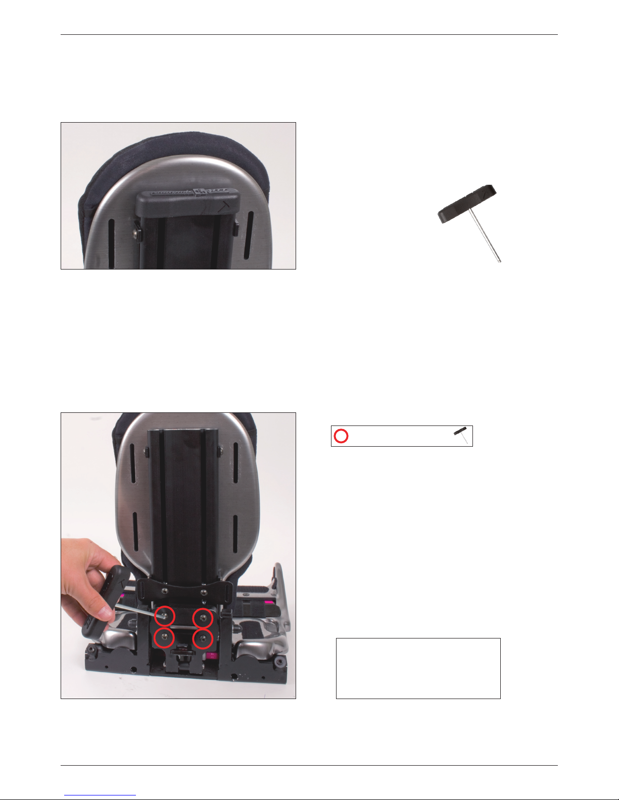
3 Verktyg
3 Mounting of the back
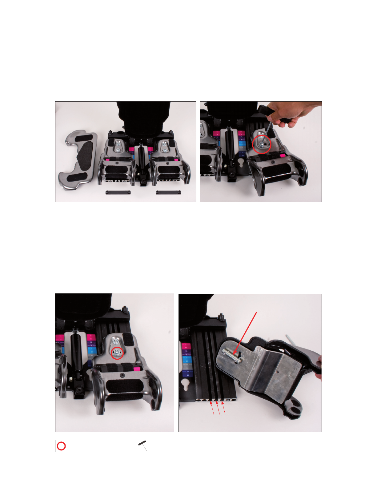
4 Seat adjustments
6 Hip angle adjustments
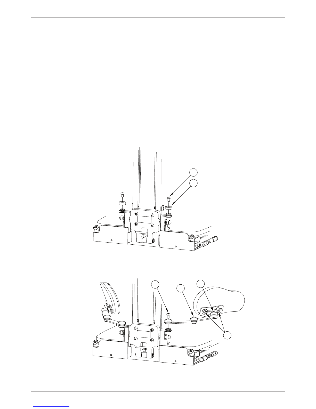
7 Back height adjustments
8 Adjustable back
9 Pelvic support
10 Hip belt
11 Mounting of the Support serie
12 Armrest
13 Upper arm support
14 Table, solid
15 Table, foldable
16 Table, reinforced
17 Footrest
18 Footrest, divided
19 Footrest, whole adjustable
20 Footrest, divided adjustable
21 Footrest, turn-up
21 Footrest, flexible adapter
22 Calf support
22 Ankle holder
22 Lumbar support
23 Driving bow
23 Heating package
24 Foldable headrest bracket
24 Headrest
25 Play bow
25 Sun cover
26 Mounting on a frame
27 Adapter system Pro
28 Headpod Bracket
28 HeadActive Bracket
28 Forehead strap Bracket
29 Footrest high edge, single stay
30 From single stay to double stay/Technical data
31 Drilling instructions whole footrest plate
32 Drilling instructions divided footrest plate
33 Technical data
34 Customer service
35 Reconditioning
36 Summary and follow-ups
37 Adaptation and customization
38 Terms of sale

User manual 3Zitzi Delfi Pro
Tool
The hexa key (4 mm) is integrated in the top of the
back and can be used to make adjustments.
Mounting of the back
The backrest is mounted with 4 bolts. Lock the
back profile by tighten the bolts. The back will
automatically be in the right place.
= Adjustment bolts
Notice!
For high tonus patients, select
reinforced back!

User manual 4Zitzi Delfi Pro
Seat adjustments
Seat depth, leg length dierance and abduction/ adduction of the legs can easily be ad-
justed. Start with take away the lining of the seat plate to get to the adjustment bolts.
Note! Do not loosen the bolt completely, just loosen it up a bit.
Seat width adjustment
To increase or reduce the seat width, the leg parts needs to be adjusted. For maximum seat
width, the rim should be in track 3, and for minimal seat width the rim should be in track 1.
- Loosen the two bolts with the hexa key.
- Move the leg part to desired track position.
- Tighten the bolts when desired position is reached.
(Default track for the leg parts is track 1)
Track 1, 2, 3
Pin
= Adjustment bolts

User manual 5Zitzi Delfi Pro
Seat slope adjustment
When adjusting the seat depth, the seat slope adjustment also should follow.
Example: If the seat deapth is adjusted to 23 cm (grey field), the seat slope also should be in the
grey field to keep an correct seat slope.
Loosen the bolt with the hexa key and move the leg part to desired track position.
Tighten the bolts when desired position is reached.
Leg length dierance
Loosen the two bolts with the hexa key and move the leg part to desired track position.
Tighten the bolts when desired position is reached.
= Adjustment bolts

User manual 6Zitzi Delfi Pro
Abduction och adduction
Loosen the bolt with the hexa key and move the leg part to desired track position. Tighten the
bolts when desired position is reached.
Hip angle adjustments
To activate the lip, pull it straight out and then
up. To adjust the angle of the back, push the lip
downwards and place it in the desired position.
When desired position is reached, let go of the
lip and put it into ”child safe mode”
It is very important that the lip is in the
safety mode, resting downwards, when
the adjustments are done.
!!
Neutral Adduction Abduction
= Adjustment bolts

User manual 7Zitzi Delfi Pro
Adjusting the back height
- Loosen the bolts (A) on both sides of the
back profile (2 on each side)
- Adjust to desired height
- Lock the bolts
Place the back so you can take usage of
the integrated lumber support!
A
= Adjustment bolts

User manual 8Zitzi Delfi Pro
Adjustable back
Adjustments
Loosen the knob (2 on each side, 4 totally)
and move the backrest to the desired
position. Tighten the knobs when
desired position is reached.
Mounting of chest pads
Mount the chest pads with the enclosed car-
riage bolt, washer and knob (see picture). The
distance should be placed between the chest
pads and the back so the fabric isn’t squashed.
Knobs

User manual 9Zitzi Delfi Pro
A
B
E
C
D
B
A
B
E
C
D
B
Mounting the pelvic support
Before you can attach the pelvic support, you must remove the protective cover
(A). Remove the screw (B) and then lift o the hood.
Mount the pelvic support where the protective cover (A) was and fix with the
screw (B).
Adjusting the pelvic support
To adjust the angle of the pelvic support, loosen the screw (B), (C) or (D),
depending on which setting you want to do. To adjust the height of the pelvic
support plate, unscrew the screws (E) and move the plate to the desired posi-
tion. Then tighten the screws (E) again.
Pelvic support

User manual 10 Zitzi Delfi Pro
A
To move the position of the hip belt, loosen the fastening screws (A) slightly and
adjust to desired position. Then tighten the screws (A).
Mounting the hip belt
When mounting the hip belt in the hip belt tracks, use a tri-glide buckle.
For assembly according to the tri-glide method, see picture.
The tri-glide method
Ensure that the belt is not clamped between the abutment and fitting.
Hip belt

User manual 11 Zitzi Delfi Pro
Mounting of the Support serie
Mounting, upper mounting bracket - A
Begin with take away the integrated hexa key that
originally is place in the top of the back profile.
Then push the upper mounting brackets to desired
position in the track of the back profile.
Adjustments of the upper mounting brackets
Loosen the bolts and make desired adjustments.
The height of the upper mounting brackets should
be place so that the pull direction is a bit above the
shoulder area. Tighten the bolts.
Mounting of strap
Pull the strap through the track and into the buckle.
Use attached Triglide buckles E.
Don’t forget to put the headrest bracket back in its
place if removed before mounting of the straps.
Adjusting the pull direction and width
Loosen the bolt of the upper mounting bracket and
adjust to desired height. Tighten the upper bolt.
Adjust the angle to desired position and tighten the
bolt.
E
(A) Upper mounting bracket
(B) Lower brackets included as standard
Alternative lower brackets (optional 285140)
Be sure that there is enough space for the
neck, that the cushions are in the right place
and that the pressure is correct!
!!
= Adjustment bolts

User manual 12 Zitzi Delfi Pro
Armrest
When mounting the armrest, pull the armrest into the bracket on the side of the chair.
Tighten the bolt (A).
Width adjustment: Loosen bolt A and adjust to desired position. Tighten the bolt.
Depth adjustment: Remove bolt B and C and adjust to desired position. Reinsert and
tighten the bolts.
Rotation: Loosen bolt C and adjust to desired position. Tighten the bolt.
Height adjustment, armrest plate: Loosen the knob (D) and adjust to desired position.
Tighten the knob.
Angle adjustment, armrest plate: Loosen the knob (E) and adjust to desired position.
Tighten the knob.
A
C
D
D
E
E
B
= Adjustment bolts

User manual 13 Zitzi Delfi Pro
A B C D E
F
F
Carriage bolt (D)
Washer (B)Finger knob (A)
Justeringsnyckel
Spakvred
Sargsprint, olika storlekar
Vagnsbult
Fingervred utv gänga
Fingervred inv gänga
Ryggbricka
Distanser
Bricka
Justeringsnyckel
Spakvred
Sargsprint, olika storlekar
Vagnsbult
Fingervred utv gänga
Fingervred inv gänga
Ryggbricka
Distanser
Bricka
Justeringsnyckel
Spakvred
Sargsprint, olika storlekar
Vagnsbult
Fingervred utv gänga
Fingervred inv gänga
Ryggbricka
Distanser
Bricka
4 pc
4 pc4 pc
Mounting
Assemble the upper arm support with the help of the finger knob (A), washer (B), and
carriage bolt (D). Note that the carriage bolt in the supports must be replaced with
longer supplied carriage bolt.
Pierce the carriage bolt (D) by the trunk support and the back plate. Then meet up with
armrests fittings (C), washer (B), and finally the finger knob (A).
Height adjustment
To adjust the height of the upper arm support, loosen the finger knob (A) and then
adjust to desired height. Tighten the finger knob (A) When you have reached the desired
position.
Width adjustment
To adjust the width of the upper arm support, loosen the screws (E) and then adjust to
the desired width. Tighten the screws (E) When you have reached the desired position.
Cushion
When the upholstery needs cleaning, you simply pull it from the armrest plate by
stretching the elastic on the back of the padding. To reassemble the upholstery, pull the
padding over the armrest pad and make sure it is centered on the armrest.
Upper arm support
When mounting the upper arm support, the carriage bolt needs to be
replaced with the longer one supplied.
When adjusting the upper arm support, even the chest pads is loosened.
!!
A B C
D
E
F
F
A B C D
E
F
F
A B C D
E
F
F

User manual 14 Zitzi Delfi Pro
Be careful not to lift the
table in the forefront.
!!
Locking lever
Fastening widths
Choose between three dierent
mounting holes
Mounting the table
Put the table on the armrest plates and then rotate the locking lever of the table into position
below the armrest plate. The locking lever must be rotated until it is inside the rim of the raised
armrest plate.
Change of mounting holes
There are 3 mounting widths to choose from. To change the width use any installation hole
under the armrest padding in the rear edge of the table. In the basic model is the locking lever
mounted in the center hole. To change mounting, you must first lift the padding at the rear. The
markings in the outer rear edge of the table only shows the size of the table.
Table, solid

User manual 15 Zitzi Delfi Pro
Position 1
Position 2 Position 3
A
B
C
Mounting the foldable table
To assemble the table push the table mounting pipe (A) through the tube (B) is located under the
armrest. Slide the table to the desired position and let it rest on the armrest plates. Tighten the finger
knob (C) to lock the table.
Using the folding operation
To fold the table aside first loosen the finger knob (C) slightly. Lift the table slightly and pull it
forward. Lift the table further and fold it aside. When the table is in its lowest position, slide it
backwards again and tighten the finger knob (C).
1) Pull the table forward
2) Lift and pull to the side
3) Fold all the way down so that the table hangs and then slide the table back to its original position
Table, foldable
Do not forget to tighten the finger knob (C) after precipitation of the table.
Make sure to pull the table far enough ahead of the side when folding so that the user is not hurt.
!!

User manual 16 Zitzi Delfi Pro
D
D
D
Mounting the reinforced table
To mount the reinforced table, push the table assembly tube (A)
through the pipe (B) located under the armrest. Then slide the table to the de-
sired position and let it rest on the armrest plates.
Tighten the finger knob (C) to lock the table. Then turn the locking lever until it
ends up inside the edge of the armrest pad.
Width adjustment of reinforced table
Instead of adjusting the width of the armrests you can choose to adjust the
width of the table mounting brackets so it fits against the mounting tubes in the
armrests fittings. To adjust the width of the table, loosen the screws (D) slightly
and adjust to desired position. Then tighten the screws (D).
Table, reinforced
If the width adjustment of the table attachment fittings is insucient may
some adjustment of the armrest width may be required.
!!
Locking lever
C
A
B

User manual 17 Zitzi Delfi Pro
8
Mounting the footrest - A
Fit the footrest in the square tube.
Secure the footrest with the locking screw.
Adjusting the knee joint - B
Loosen the knob (B) and adjust to desired position.
Tighten when desired positions is reached.
Important - The ”teeth” have to fit with each other.
Lock the bolt properly!
Angle adjustment, foot joint - C
Loosen the knob (C) and adjust to desired position.
Tighten when desired position is reached.
Height adjustment, foot plate - D
Loosen the knob (D) and adjust to desired position.
Tighten when desired positions is reached.
(D) Bolts for footrest height
(B) Angle adjustment knob,
knee-joint
(C) Bolts for footrest angle
(A) Attachment, foorest
Knob for knee joint
Footrest
= Adjustment bolts

User manual 18 Zitzi Delfi Pro
8
Montering av fotstöd - A
Fit the footrest in the square tube.
Secure the footrest with the locking screw.
Adjusting the knee joint - B
Loosen the knob (A) and adjust to desired position.
Tighten when desired positions is reached.
Important - The ”teeth” have to fit with each other.
Lock the bolt properly!
Height adjustment, foot plate - C
Loosen the knob (C) and adjust to desired position.
Tighten when desired positions is reached.
(B) Angle adjustment knob,
knee-joint
(A) Attachment, foorest
(A) Knob for
knee joint
(D) Screw
(C) Screw
Divided footrest
= Adjustment bolts

User manual 19 Zitzi Delfi Pro
Angle adjustments, knee joint - A
Loosen the bolt (A) and adjust to desired position. Tighten when desired positions is reached.
Height adjustment, foot plate - B
Loosen the knob (B) and adjust to desired position. Tighten when desired positions is reached.
Angle adjustments, foot joint - C
Loosen the bolts (C) and adjust to desired position. Tighten when desired positions is reached.
Adjusting the foot plate - D
The foot plates width and depth can be adjusted. Loosen the bolts (D) and adjust to desired
position. Tighten when desired positions is reached.
(C) Angle adjustments, foot joint
(B) Height adjustment, foot plate
(A) Knob,
knee joint
(D) Adjusting the foot plate
Footrest
attachment
Footrest - whole, adjustable
= Adjustment bolts

User manual 20 Zitzi Delfi Pro
Angle adjustments, knee joint - A
Loosen the bolt (A) and adjust to desired position. Tighten when desired positions is reached.
Height adjustment, foot plate - B
Loosen the knob (B) and adjust to desired position. Tighten when desired positions is reached.
Angle adjustments, foot joint - C
Loosen the bolts (C) and adjust to desired position. Tighten when desired positions is reached.
Adjusting the foot plate - D
The foot plates width and depth (!) can be adjusted. Loosen the bolts (D) and adjust to desired
position. Tighten when desired positions is reached.
(C) Angle adjustments, foot joint
(B) Height ad-
justment, foot
plate
(D) Adjusting the foot plate
Footrest - Divided adjustable
(A) Knob
knee joint
Footrest
attachment
Table of contents
Other Zitzi Wheelchair manuals