ZIV MBPU User manual

Communication solutions for power utilities
1/28
DIMAT
A
ntonio Machado,78-80
08840 Viladecans,
Barcelona-Spain
Tel.: +34 933 490 700
Fax: +34 933 492 258
www.dimat.com
UNIVERSAL POWER-LINE CARRIER SYSTEM
TYPE OPU-1
WHOLE BAND QAM MODEM
MBPU
Rev. 0 - July 2011

Communication solutions for power utilities
UNIVERSAL POWER-LINE CARRIER SYSTEM TYPE OPU-1
WHOLE BAND QAM MODEM MBPU - Rev. 0 (July 2011) 2/28
!
SAFETY SYMBOLS
!
WARNING OR CAUTION:
This symbol denotes a hazard. Do not follow the indicated procedure,
operation or such like, it could mean a total or partial breakdown of the
equipment or even injury to the personnel handling it.
NOTE:
Information or important aspects to take into account in a procedure,
operation or such like.

Communication solutions for power utilities
UNIVERSAL POWER-LINE CARRIER SYSTEM TYPE OPU-1
WHOLE BAND QAM MODEM MBPU - Rev. 0 (July 2011) 3/28
TABLE OF CONTENTS
Page
1INTRODUCTION 4
1.1 GENERAL 4
1.2 CONSTITUTION OF THE MODEM 4
1.3 TECHNICAL CHARACTERISTICS 5
2OPERATING PRINCIPLE 7
2.1 MODULATION STANDARD AND SPEED 7
2.2 DATA TRANSMISSION IN ASYNCHRONOUS MODE 7
2.3 EQUALIZATION AND RECONDITIONING (RETRAIN) 8
2.4 MODEM RESET 8
3INSTALLATION 9
3.1 MODULE ARRANGEMENT 9
3.2 TERMINAL BLOCK 9
4COMMISSIONING 12
4.1 FRONT-PLATE ELEMENTS 12
4.1.1 Optical indicators 12
4.1.2 Button Pl1 14
4.2 INTERNAL ELEMENTS 14
4.2.1 MI1 microswitch 15
4.2.2 Switch 15
4.2.3 Jumpers 15
4.3 LEVELS 16
4.4 CONFIGURATION STORAGE 16
5PROGRAMMING 17
5.1 AT COMMAND 17
5.1.1 Format of the AT commands 17
5.1.2 Group of AT commands 18
5.2 S REGISTERS 22

Communication solutions for power utilities
UNIVERSAL POWER-LINE CARRIER SYSTEM TYPE OPU-1
WHOLE BAND QAM MODEM MBPU - Rev. 0 (July 2011) 4/28
1 INTRODUCTION
1.1 GENERAL
The MBPU is a modem with a programmable modulation scheme, especially designed to
work in point to point Power-Line Carrier (PLC) links for the transmission of synchronous or
asynchronous data at a speed of up to 28800 bit/s in line.
The MBPU modem is capable of operating with frequency-shift keying (FSK) modulation
according to Recommendations V.23 and V.21 of ITU-T, as well as with multi-level
modulations (DPSK, QAM and TCM) according to Recommendations V.34, V.32bis, V.32,
V.22bis and V.22 of ITU-T.
The MBPU modem is made up of a single module, which can be totally incorporated in an
OPU-1 Universal Power-Line Carrier terminal, from which it receives the power supply. It
has two types of interface: V.24/V.28 of the ITU-T (with one clock for emission and another
for reception) and V.11 in accordance with standard ISO 4903 (a single clock).
It is possible to execute AT commands in order to modify the modem programming and
request the state of specific parameters, from a compatible Personal Computer (PC) that
has a communications emulator program, such as for example HyperTerminal. It is also
possible to configure certain parameters of the MBPU by means of the internal
microswitches and jumpers in the module.
1.2 CONSTITUTION OF THE MODEM
The MBPU modem is made up of a single-printed circuit board containing the circuitry of the
modem, all the adaptive circuits necessary for the connection of the transmission and
reception signals of the modem to the corresponding buses associated to the analog
channel of the OPU-1 terminal, the connection circuits associated to the elements on the
front plate, a programmable logic, the voltage stabilizers, as well as the jumpers and
microswitches to be configured by the user.
There is a button on the front plate for carrying out a terminal reset as well as for entering in
programming mode by means of AT commands.

Communication solutions for power utilities
UNIVERSAL POWER-LINE CARRIER SYSTEM TYPE OPU-1
WHOLE BAND QAM MODEM MBPU - Rev. 0 (July 2011) 5/28
There are also optical indicators to display:
−The state of the logic signals of the interface.
−The data interface selected (V.24/V.28 or V.11).
−When a reset is being carried out in the module.
−When the module is in programming mode by means of AT commands.
1.3 TECHNICAL CHARACTERISTICS
Transmission mode Full-duplex point to point link
Transmission speed Between 300 and 28800 bit/s
Modulation
A
ccording to V.34, V32bis, V.32, V.22bis, V.22, V.23
and V.21 standards of the ITU-T, at different line
speeds (see Table 1).
A
specific standard may be configured or it can be
established that a standard is configured automatically
by means of negotiation during connection.
ITU-T standard Speed in line (bit/s) Modulation AT command
AUTO - - ATF0
V.34 28800 SM-TCM of 4 to 1024 points ATF16
V.34 26400(1) SM-TCM of 4 to 1024 points ATF15
V.34 24000 SM-TCM of 4 to 1024 points ATF14
V.34 21600 SM-TCM of 4 to 1024 points ATF13
V.34 19200 SM-TCM of 4 to 1024 points ATF12
V.34 16800 SM-TCM of 4 to 1024 points ATF11
V.32bis 14400 TCM-128 ATF10
V.32bis 12000 TCM-64 ATF9
V.32 9600 TCM-32 ATF8
V.32bis 7200 TCM-16 ATF7
V.32 4800 QAM-4 ATF6
V.22bis 2400 QAM-16 ATF5
V.22 1200 DPSK-4 ATF4
V.23 1200/75 or 75/1200 FSK ATF3
V.21 300 FSK ATF1
Table 1 Operating modes
(1) Only for use in asynchronous mode.

Communication solutions for power utilities
UNIVERSAL POWER-LINE CARRIER SYSTEM TYPE OPU-1
WHOLE BAND QAM MODEM MBPU - Rev. 0 (July 2011) 6/28
Data format Synchronous: bit to bit.
Asynchronous:
Direct mode: V.14 conversion. Character
length of 8, 9, 10 or 11 bits.
With buffer
Data interface
Standard V.24/V.28 of the ITU-T (RS-232) and V.11 according
to ISO 4903
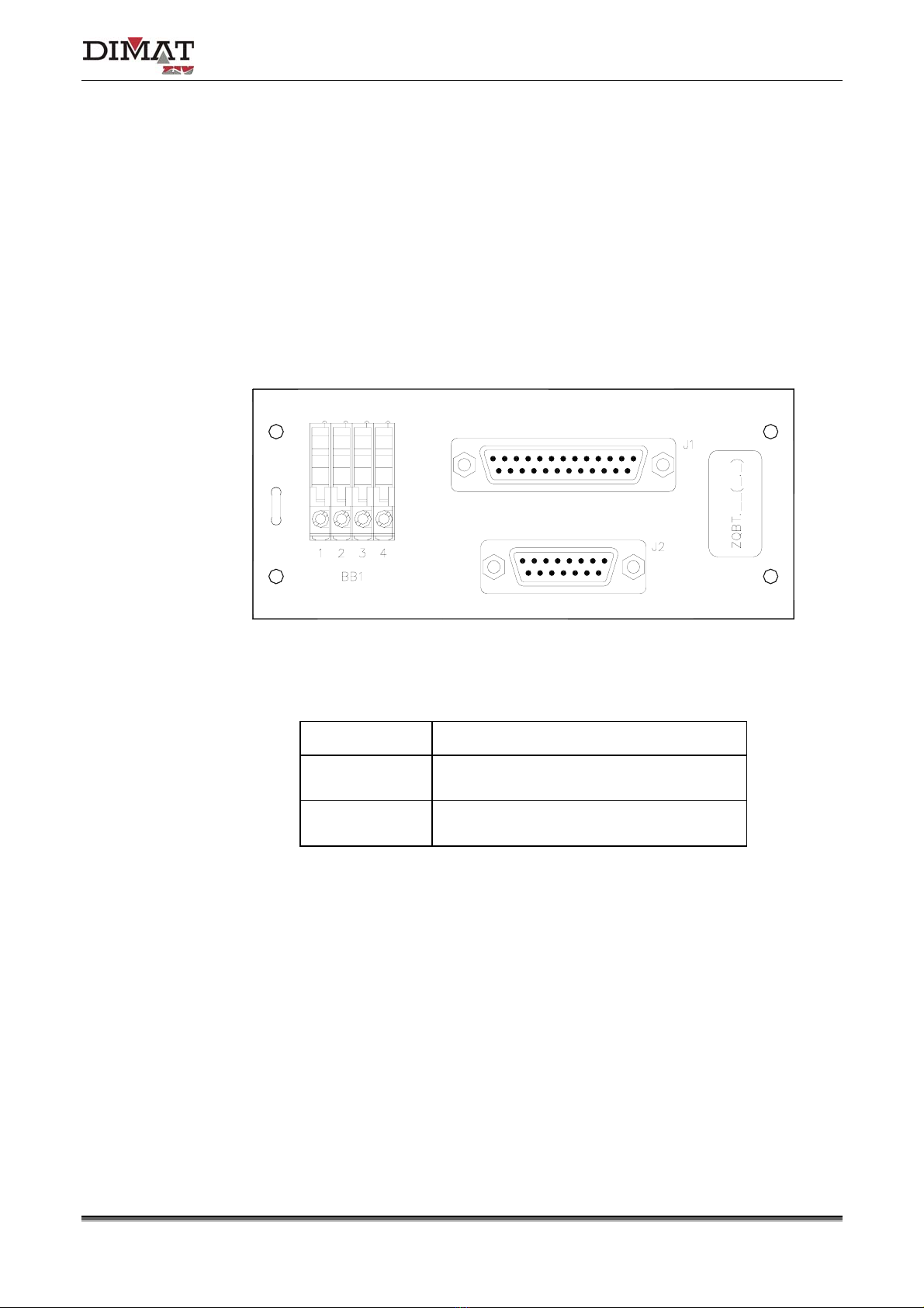
Type of connector 25-pin SUB-D (J1 of ZQBT) for V.24/V.28 and
15-pin SUB-D (J2 of ZQBT) for V.11
Speed with the DTE Asynchronous: 28800, 26400, 24000, 21600,
19200, 16800, 14400, 12000, 9600, 7200, 4800,
2400, 1200 and 300 bit/s.
Synchronous: 28800, 24000, 21600, 19200, 16800,
14400, 12000, 9600, 7200, 4800, 2400, 1200 and
300 bit/s
Speed with the
programming PC
Asynchronous: 38400, 28800, 19200, 14400, 9600,
7200, 4800, 2400, 1200, 600, 300 and 75 bit/s
Optical indications - State of the logic signals of the interface
(TD, RD, RTS, CTS, DSR, DTR and DCD).
- Modem connected to the line (OH).
- Type of interface (V.24 or V.11).
- Hardware reset of module (AUX lights up in red) or
module in programming mode by means of AT
commands (AUX blinks in green)
Connections ZQBT terminal block
Dimensions Height: 262 mm; Width: 30 mm; Depth: 256 mm
(with handles)
Weight 350 g

Communication solutions for power utilities
UNIVERSAL POWER-LINE CARRIER SYSTEM TYPE OPU-1
WHOLE BAND QAM MODEM MBPU - Rev. 0 (July 2011) 7/28
2 OPERATING PRINCIPLE
2.1 MODULATION STANDARD AND SPEED
The MBPU modem has 7 modulation standards: V.34, V.32bis, V.32, V.22bis, V.22, V.23
and V.21, at different line speeds.
It can be programmed by means of commands AT, in order to operate at a predetermined
speed and modulation standard.
Table 1 shows the possible standards, their transmission speeds associated, and the AT
Hayes commands that configure the modem in order for it to operate according to the said
standards and speeds.
The automatic modulation scheme detection mode, that is programmed by means of
command ATF0 or ATN1, must always operate with modulations that comply with the ITU-T
standards (except V.22 at 600 bit/s QAM).
2.2 DATA TRANSMISSION IN ASYNCHRONOUS MODE
There are two asynchronous operating modes: direct or with intermediate storage
(buffering). The modem has a memory storage area (buffer), both in transmission and
reception, so that it can transmit at its own speed without having to depend on that of the
data terminal equipment.
It is possible to disable the intermediate storage mode (buffering), functioning therefore in
direct mode, by means of command AT\N1 or AT&Q0. In direct mode, the speed selected in
the communications program must be the same as that of the line speed.
The character format used by the series interface is selected according to the result of the
automatic speed negotiation or autobauding or, in the opposite case, to the S23 register.
The asynchronous formats permitted are those that include 1 start bit, 7 or 8 data bits, even
parity, odd parity or none, and 1 or 2 stop bits.

Communication solutions for power utilities
UNIVERSAL POWER-LINE CARRIER SYSTEM TYPE OPU-1
WHOLE BAND QAM MODEM MBPU - Rev. 0 (July 2011) 8/28
2.3 EQUALIZATION AND RECONDITIONING (RETRAIN)
The modem has an automatic adaptive equalizer that operates according to standards
V.22bis and higher (V.32, V.32bis and V.34). This equalizer continually supervises line
conditions, adapting it to them in order to guarantee optimum reception. If the equalizer
detects a marked decrease in the line quality, the modem is capable of generating a retrain
request according to the standard that is active. It will also answer a request from the
remote modem if necessary. The terminal will attempt a retraining up to three times before
disconnecting from the line.
2.4 MODEM RESET
Two types of reset, hardware and software, can take place in the MBPU modem.
The hardware reset occurs in the modem when the Pl1 button on the front plate is pressed
for more than 2 seconds (long pressing) or when the activation of the Unavailable link(2)
signal is received, by means of the programming and control bus of the OPU-1 terminal.
The LED AUX on the front plate lights up in red to indicate this type of reset.
The software reset is produced internally in the modem when a training sequence should
begin or when the period of time determined by the S35 register has elapsed.
(2) The conditions that activate the Unavailable link signal are specified in the OPU-1 terminal by means of programming,
Pilot loss, Low S/N ratio, Loss of synchronism and Boosting must at least be programmed.

Communication solutions for power utilities
UNIVERSAL POWER-LINE CARRIER SYSTEM TYPE OPU-1
WHOLE BAND QAM MODEM MBPU - Rev. 0 (July 2011) 9/28
3 INSTALLATION
This chapter describes the installation of the MBPU modem in the 6 s.u. shelf of the
Universal Power-Line carrier terminal type OPU-1, together with the cabinet-mounted
terminal block associated to the modem module.
3.1 MODULE ARRANGEMENT
The MBPU module can be installed in the last five positions of the 6 s.u. shelf, provided the
said positions are not already occupied by other options. It must be kept in mind that the first
shelf position corresponds, seen from the front, to module POWER SUPPLY (FAPU).
The module must only be inserted when the power supply of the OPU-1 is not connected.
The MBPU module has two fixing screws, one at the top and one at the bottom of the
front plate.
To extract the module, turn the two fixing screws anti-clockwise as far as allowed. Then by
means of the handles pull the module out of the shelf.
Inserting the module in the shelf is achieved by carrying out the extraction process in
reverse. Once the module has been inserted, the fixing screws must then be turned
clockwise.
3.2 TERMINAL BLOCK
The terminal block associated to the MBPU module is called ZQBT.
The block is fastened to the OPU-1 cabinet-mounted terminal block by means of screws.
The connection between the block and the equipment is carried out by means of a cable.
The ZQBT terminal block is made up of:
−Four terminals that will allow a filter or an external equalizer to be inserted, provided
jumpers J10 and J11 are in position B.

Communication solutions for power utilities
UNIVERSAL POWER-LINE CARRIER SYSTEM TYPE OPU-1
WHOLE BAND QAM MODEM MBPU - Rev. 0 (July 2011) 10/28
−A 25-pin female SUB-D type connector for connection to a RS-232C interface, provided
microswitch MI1-4 is configured in ON.
−A 15-pin female SUB-D type connector for connection to a V.11 interface according to
Recommendation ISO 4903, provided microswitch MI1-4 is configured in OFF.
Table 2, Table 3 and Table 4 show the use of the BB1 block and the J1 and J2 connectors.
Figure 1 shows the front view of the block. The terminals have disconnect devices and are
suitable for 2.5 mm2flexible conductors and 4 mm2rigid conductors.
Figure 1 Terminal block of the MBPU module
ZQBT-BB1 block Use
1
2 AF XMT signal
3
4 AF RCV signal
Table 2 Signals of ZQBT-BB1

Communication solutions for power utilities
UNIVERSAL POWER-LINE CARRIER SYSTEM TYPE OPU-1
WHOLE BAND QAM MODEM MBPU - Rev. 0 (July 2011) 11/28
SUB-D 25 pin Circuit no. DTE/DCE* V.24/V.28 signal
1 101 - Protective ground
2 103A
⇒TXD
3 104A
⇐RXD
4 105A
⇒RTS
5 106A
⇐CTS
6 107A
⇐DSR
7 102 - GND
8 109A
⇐DCD
15 114A ⇐TXCLK
17 115A ⇐RXCLK
20 108A ⇒DTR
24 113A ⇒EXT CLOCK
* The DTE/DCE column shows the direction of each of the signals involved,
the MBPU modem corresponding to the Data Circuit Equipment (DCE).
Table 3 Signals V.24/V.28 of connector J1 of terminal block ZQBT
SUB-D 15 pin Signal DTE - DCE* ISO 4903
designation
1 Protective ground - -
2 Transmission (A) ⇒T (A)
3 Control (A) - C (A)
4 Reception (A) ⇐R (A)
5 Indication (A) - I (A)
6 Signal timing (A) ⇐S (A)
7 External clock (A) ⇒X (A)
8 Signal ground - G
9 Transmission (B) ⇒T (B)
10 Control (B) - C (B)
11 Reception (B) ⇐R (B)
12 Indication (B) - I (B)
13 Signal timing (B) ⇐S (B)
14 External clock (B) ⇒X (B)
15 Not used - -
* The DTE/DCE column shows the direction of each of the signals involved,
the MBPU modem corresponding to the Data Circuit Equipment (DCE).
Table 4 Signals V.11 of connector J2 of terminal block ZQBT

Communication solutions for power utilities
UNIVERSAL POWER-LINE CARRIER SYSTEM TYPE OPU-1
WHOLE BAND QAM MODEM MBPU - Rev. 0 (July 2011) 12/28
4 COMMISSIONING
This chapter deals with the functions of the elements accessible from the front plate as well
as the internal microswitches, switch and jumpers.
4.1 FRONT-PLATE ELEMENTS
The front view of the module is shown in Figure 2. All the accessible elements are described
below, in a downward order and from left to right.
4.1.1 Optical indicators
TD/103 LED Green. Indicates data input and lights up when a logical level “0” is
applied.
RD/104 LED Green. Indicates data output. This LED lights up when a logical
level “0” is received.
RTS/105 LED Green. Indicates request to transmit and lights up when the signal
is in active state.
CTS/106 LED Green. Indicates the modem is ready to transmit and lights up
when the signal is in active state.
DSR/107 LED Green. Indicates the modem is working correctly.
DTR/108 LED Green. Lights up when the state of the signal is active in the data
terminal.
DCD/109 LED Green. Indicates the detection of line signals and lights up when
the level of the carrier is above a pre-set level. It goes out in the
opposite case.
OH LED Green. When lit indicates line has been taken by the modem.
V.11 LED Amber. This LED lights up when the modem has been configured
with interface V.11.
V.24 LED Amber. This LED lights up when the modem has been configured
with interface V.24.

Communication solutions for power utilities
UNIVERSAL POWER-LINE CARRIER SYSTEM TYPE OPU-1
WHOLE BAND QAM MODEM MBPU - Rev. 0 (July 2011) 13/28
AUX LED The LED lights up in red when a hardware reset is taking place in the
modem (see section 2.4, MODEM RESET) and blinks in green when
the module is in programming mode by means of AT commands.
Figure 2 Front view of the MBPU module

Communication solutions for power utilities
UNIVERSAL POWER-LINE CARRIER SYSTEM TYPE OPU-1
WHOLE BAND QAM MODEM MBPU - Rev. 0 (July 2011) 14/28
4.1.2 Button Pl1
When the button is pressed for more than 2 seconds (long pressing), a hardware reset is
carried out in the modem. The LED AUX remains lit in red during the reset.
When the button is pressed for less than 2 seconds (short pressing), the module enters in
programming mode by means of AT commands. The LED AUX continues to blink in green
whilst the module is in this programming mode. It is necessary to carry out a hardware reset
in order to leave the programming mode by means of AT commands.
4.2 INTERNAL ELEMENTS
This section describes the function of the internal measurement and configuration elements
of the MBPU module, see Figure 3.
Figure 3 Position of the configuration and measurement elements of the MBPU module

Communication solutions for power utilities
UNIVERSAL POWER-LINE CARRIER SYSTEM TYPE OPU-1
WHOLE BAND QAM MODEM MBPU - Rev. 0 (July 2011) 15/28
4.2.1 MI1 microswitch
Microswitch 1: Selection of Master/Slave.
ON Slave (Responder).
OFF Master (Originator).
Microswitches 2 and 3: Selection of synchronism mode.
Microswitch
2 3 Description
ON ON Asynchronous
ON OFF Synchronous internal clock
OFF ON Synchronous external clock
OFF OFF Synchronous slave clock
Table 5 Selection of synchronism mode
Microswitch 4: Selection of data interface.
OFF V.11 interface.
ON V.24 interface.
4.2.2 Switch
CM1 Selection of the Power-line Carrier terminal analog channel.
CH1: Channel 1.
CH2: Channel 2.
4.2.3 Jumpers
J10 and J11 Routing of AF signals.
A: Direct channel (OPU-1 buses associated to analog
channel).
B: ZQBT terminal block
(4-wire input and output terminals).
J5 Activation of the RTS signal.
OFF: According to interface.
ON: Permanent.

Communication solutions for power utilities
UNIVERSAL POWER-LINE CARRIER SYSTEM TYPE OPU-1
WHOLE BAND QAM MODEM MBPU - Rev. 0 (July 2011) 16/28
4.3 LEVELS
The transmit and receive levels must be programmed when the AF signals are routed by
means of the ZQBT terminal block (jumpers J10 and J11 in position B).
The programming of the input and output levels associated to the corresponding option, for
example Digital Transit Filter, is carried out from the OPU-1 Management System, by
means of the Input levels and Output levels options of the basic equipment, by establishing
a level of -7 dBm.
4.4 CONFIGURATION STORAGE
The modem configuration includes the operation options selected for a particular
application. This configuration can be modified locally by means of the AT commands or by
the internal microswitches and jumpers in the module.
The modem has a configuration storage area, known as the user profile, that is situated in
the E2ROM non-volatile memory. The moment it is started up, or after a software reset
(command ATZ), the modem loads the contents of the user profile, using it from then on as
active configuration. In order to modify the user profile it is only necessary to:
−Change the necessary operative parameters of the modem by means of the corresponding
commands, and
−store the resulting active configuration in the user profile available, by means of the
command AT&W.
The modem also has a fixed configuration, known as factory profile, that is stored in the
read-only memory. The user can retrieve this profile (by means of AT&F) and convert it into
the active configuration of the modem, and store it as the user profile by defect (by means of
AT&W).
A factory profile is re-established as an active configuration by means of AT&F command.
The active configuration can be displayed by means of the AT\S command, whilst the AT&V
command shows the factory and user profile.

Communication solutions for power utilities
UNIVERSAL POWER-LINE CARRIER SYSTEM TYPE OPU-1
WHOLE BAND QAM MODEM MBPU - Rev. 0 (July 2011) 17/28
5 PROGRAMMING
The modem configuration includes the operation options selected for a particular
application. When working with the V.24 interface, connector J1 of the ZQBT block, this
configuration can be modified by means of the AT commands, from a compatible Personal
Computer (PC) that has a communications emulator program, such as for example
HyperTerminal.
When working with the AT commands, the modem interface allows the speed, parity and
character length used by the programming PC, according to on the AT header of each
command user, to be automatically adapted. The automatic length and parity adaptive
procedure is capable of detecting characters of 7 and 8 bits and even parity, odd parity, or
none and speeds of between 75 and 38400 bit/s. If this procedure is not carried out the
modem remains configured at the speed and parity specified in the S23 register, or at those
in which the profile recording command AT&W has been introduced.
5.1 AT COMMAND
5.1.1 Format of the AT commands
When working with the AT commands, with the exception of command A/, each command
transmitted by the PC must start with the AT sequence of characters and must end with a
return. The commands can be transmitted in either capital letters or small letters. A
command can be aborted at any time by introducing <CTRL X>.
The AT sequence can be followed by a list of commands in sequence, separated or not by a
space, except for the Z commands, as the commands that follow these last ones will be
ignored. The maximum number of characters in any line of commands is 75, including A and
T. If a syntax error is detected in any command, the rest of the line is ignored and an
ERROR message is sent to the PC. The blank spaces in a command will be ignored.
Before sending another command wait for the result of the previous one.

Communication solutions for power utilities
UNIVERSAL POWER-LINE CARRIER SYSTEM TYPE OPU-1
WHOLE BAND QAM MODEM MBPU - Rev. 0 (July 2011) 18/28
5.1.2 Group of AT commands
The modem accepts the group of AT commands detailed below. The possible values of their
parameters as well as their significance are indicated for each of the commands. If you do
not enter any value, it will be equivalent to 0.
Parameters:
[X] digit
A/ Repetition of the last command
The modem will act as if it has received the last line of commands from the PC
again. This command should not be preceded by the AT sequence, and is carried
out without the transmission of the return.
C[X] Carrier control
C0 Continuous carrier. (by default)
C1 Controlled carrier.
&C[X] RLSD circuit control (CD or 109)
The 109 circuit of the V.24 interface, connector J1, and the corresponding LED on
the front plate will act according to the parameter of this command.
&C0 109 circuit (CD) always ON.
&C1 109 circuit (CD) adapts to the line carrier. (by default)
&D[X] DTR option
This command indicates the modem how it has to treat a fall in the DTR signal
(circuit 108) according to the parameter:
&D0 The DTR signal is ignored. (by default)
&D1 The modem will respond to an ON/OFF transition of the DTR signal as if
it had received an scape sequence in asynchronous format, and will
disconnect from the line in synchronous format.
&D2 The modem will respond to an ON/OFF transition of the DTR signal by
disconnecting from the line.
&D3 The modem will respond to an ON/OFF transition of the DTR signal as if
it had carried out a software reset in asynchronous format, and
disconnecting from the line in synchronous format.

Communication solutions for power utilities
UNIVERSAL POWER-LINE CARRIER SYSTEM TYPE OPU-1
WHOLE BAND QAM MODEM MBPU - Rev. 0 (July 2011) 19/28
%D[X] Autobauding option
%D0 Disables autobauding.
%D1 Enables autobauding. (by default)
E[X] Echo command
The modem will enable or disable the echo of the characters transmitted by the
DTE according to the parameter provided.
E0 No echo.
E1 Echo enabled. (by default)
F[X] Modulation selection
This command selects the modulation scheme in line according to the parameter
provided. The modulation is fixed, except when automatic mode is selected.
F0 Selects the automatic mode.
F1 V.21 at 300 bit/s FSK.
F2 Ignored.
F3 V.23 75TX/1200RX in call mode or 1200TX/75RX in answering mode.
F4 V.22 at 1200 bit/s QAM.
F5 V.22bis at 2400 bit/s QAM. .
F6 V.32 at 4800 bit/s.
F7 V.32bis at 7200 bit/s.
F8 V.32 at 9600 bit/s.
F9 V.32bis at 12000 bit/s.
F10 V.32bis at 14400 bit/s.
F11 V.34 at 16800 bit/s.
F12 V.34 at 19200 bit/s.
F13 V.34 at 21600 bit/s.
F14 V.34 at 24000 bit/s.
F15 V.34 at 26400 bit/s (only for use in asynchronous mode).
F16 V.34 at 28800 bit/s. (by default).
&F Re-establish factory configuration
Re-establish all the configurations by default.
&G[X] Guard tone selection (only DPSK modulations)
&G0 Disable guard tone.
&G1 Select guard tone of 1800 Hz. (by default)

Communication solutions for power utilities
UNIVERSAL POWER-LINE CARRIER SYSTEM TYPE OPU-1
WHOLE BAND QAM MODEM MBPU - Rev. 0 (July 2011) 20/28
\G[X] Modem-modem flow control (XON/XOFF)
\G0 Disable modem-modem flow control. (by default)
\G1 Enable modem-modem flow control.
%G[X] Fallback/Fallforward
%G0 Disabled. (by default)
%G1 Enabled.
&K[X] Selection of the DTE-modem flow control
&K0 Disable flow control.
&K3 Enable RTS/CTS flow control. (by default)
&K4 Enable XON/XOFF flow control.
&K5 Enable XON/XOFF transparent flow control.
&K6 Enable RTS/CTS and XON/XOFF together.
%L Received signal level
Sends back the value of the input signal (in negative dBm).
N[X] Enable automatic modulation detection
N0 Disabled. (by default)
N1 Enabled (equivalent to ATF0).
\N[X] Asynchronous transmission mode
\N0 Bufferized mode (equal to AT&Q5). (by default)
\N1 Direct mode (equal to AT&Q0).
%O[X] Overspeed option
The overspeed allows a higher speed tolerance in the V.24 interface in
asynchronous mode.
%O0 Disables overspeed (±1%).
%O1 Enables overspeed (±2.5%). (by default)
&Q Transmission mode
&Q0 Direct asynchronous mode.
&Q1 Selects synchronous on-line operating mode and asynchronous in
commands. (by default)
&Q2 Selects synchronous on-line operating mode and asynchronous in
commands.
Table of contents
Other ZIV Modem manuals