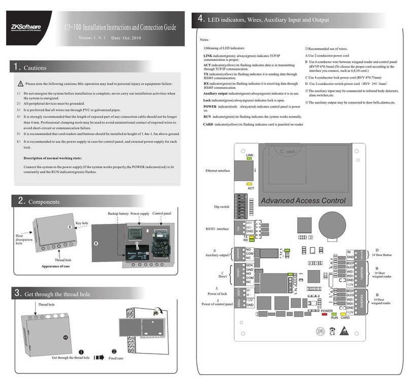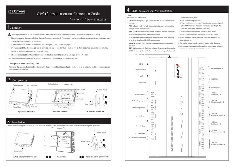
8.Equipment Communication
P C
P C
485+
485-
GND
485+ 485+ 485+
485- 485- 485-
GND GND GND
1. TCP/IP Communication
2. RS485 Communication
The PC software can communicate with the panel according to the communication protocols (RS485 and TCP/IP) for data exchange and
remote management. The communication cable should be away from high-voltage lines as far as possible. Do not keep the communication
cable in parallel with power cords or bind them together.
Switch
n# control panel
serial line
1# control panel 2# control panel
485
Converter
DIP Switch
8# Control panel
2# Control panel
1# Control panel
1) Internationally accepted RVSP (shielded twisted-pair) wires should be used for communication to effectively avoid interference. RS485
of bus cascade connection. communication wires should be connected by means
3) One RS485 bus may hold 63 control panels, but it is not recommended to connect with less than 32 .access control panels
Notes:
5) When the wire is longer than 300 meters, to enhance the stability of communication, it is necessary to keep number 8 switch of
2) Considering stability of communication, it is recommended that the RS485 bus should be less than 600 meters.
system. As shown in the figure above, turn number 8 of the DIP switches of the 1# and 8# at "ON” status.
the first and the last control panel at “ON” status. That is add the RS485 terminal resistance (120 ohm) of the two devices to the
1 2 3 4
O
5 6 7 8
N
STATE
PWR
EXT
RS48 5
PC
RS48 5
SWIT CH
STATE
PWR
EXT
RS48 5
PC
RS48 5
SWIT CH
STATE
PWR
EXT
RS48 5
PC
RS48 5
SWIT CH
STATE
PWR
EXT
RS48 5
PC
RS48 5
SWIT CH
STATE
PWR
EXT
RS485
PC
RS485
SWITC H
STATE
PWR
EXT
RS485
PC
RS485
SWITC H
STATE
PWR
EXT
RS48 5
PC
RS48 5
SWIT CH
STATE
PWR
EXT
RS48 5
PC
RS48 5
SWIT CH
1
2
4
8
16
32
+
+
+
-
-
NC
NO
GND
COM
SEN
+
+
-
-
FR 10 7
FR 10 7
6.Lock Connection
-
LED
1
2
3
4
5
5. DIP Switch Settings
1) Number1-6 switch are used to set the number in communication: control panel RS485 It is adopted binary coding and little endian, the address
corresponding desired status, and the address number should not be repeated in the network. switches to the
2) Number7 switch is used to restore factory default settings:
3) Number 8 switch is used to set terminal resistance in RS485
Restore Factory Settings
RS485 Terminal Resistance
3) When the Electrical Lock is connected to the access control system, you need to parallel one FR107 diode (equipped in the package) to prevent
1) The control panel provides lock control output interfaces. For NO lock, it is normal open when power is on, so COM and NO terminals should
2) The control panel supports “dry mode” and “wet mode” by using the jumper. It is recommended to use “wet mode” when you connect “V+”
NO Lock
LOCK
LOCK
Enlarged diagram
of lock terminals
NC Lock
Lock Power
Diode
Diode
Jumper
terminal
1 2 3 4
O
5 6 7 8
N
number setting by place these 6 switches are shown as figure below. Before setting the address, please keep the system power off. Place the
For example: Set the device number as 39 (39=1+2+4+32), the switches status is 111001, that is set number 1, 2, 3 and 6 switches at “ON”.
the system restores factory default settings.
be used. For NC lock, it is normal closed when power is off, so COM and NC terminals should be used.
and “ V-” terminals for lock power supply. That is short 2-3 and 4-5 terminals. The factory default setting is dry mode. For “dry mode” and
“wet mode” settings, please refer to the Access Control Panel Installation Guide.
The following is the lock connection of “wet mode” with external power supply .
the self-inductance EMF affecting the system, do not reverse the polarities.
Stick the screw driver to the rectangular hole on the four corner of the panel back, switch it from outside to inside. After hearing the "click"
sound, you can remove the case from the panel.
7. 485 Reader (inBIO Reader) Connection
P C 48 5+
485-
GND
#1 Reader # 1 Reader #8 Reader
communication: Switch it to“ON” status, that is add a
terminal resistance of 120 ohm between 485+ and 485-.
Switch it for three times within 10 seconds and restart the
system, then all data in control panel will be cleared and
The control panel supports inBIO biometric verification
for reader changing. Realize the real biometric reader
485 reader connection: First of all, set the 485 address
(device number) of reader by software, DIP switch or
keypad method. Such as the reader 1, 2 (the odd number
is for enter reader, and the even number is for exit reader),
the 485 address is 1, 2, and the door number is 1. Such as
refer to the software user manual.
the right figure connection. For more information, please
reader and Wiegand reader. In use of inBIO reader, all
in control panel. No need to re-register the fingerprints
operations including storage, verification, etc. execute
connection.
4) When EXT485 terminals connected with inBIO Reader, it is recommended that the wire should be less than 100 meters.


