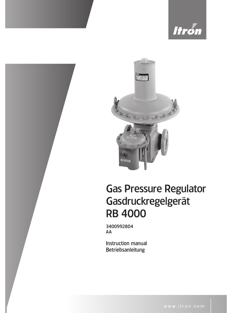
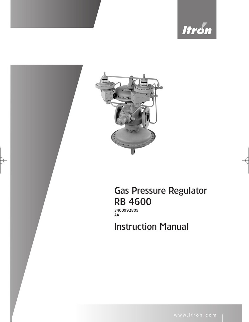
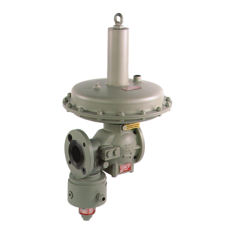
ITRON RR 16 User manual

RR16
Gas Pressure Regulator
Gasdruckregelgerät
Régulateur de pression
Ðåãóëÿòîð äàâëåíèÿ ãàçà
Regulátor tlaku plynu
Instruction Manual
Betriebsanleitung
Mode d’emploi
Ðóêîâîäñòâî ïî ýêñïëóàòàöèè
Náod k obsluze
GAS
EN
DE
FR
RU
CZ
111-099-2801-AD

2

3
CONTENTS PAGE
Schematic section regulator/ Material.................................................................................................................................................... 5
Description / technical data / Type-Selection ........................................................................................................................................ 6
Spring range regulator and SSV .......................................................................................................................................................7 – 8
Safety instructions and EU Declaration of Conformity ....................................................................................................................9 – 10
Instruction of installation regulator and SSV / Service and repair..................................................................................................11 – 12
Damping precautions / Flow disc .................................................................................................................................................12 – 13
Installation silencer / SSV-Position indicator .........................................................................................................................................14
Description of manipulation-valve (selfe closing).................................................................................................................................. 15
Start-up instruction of SSV 033, SL-IZ.., 022 and SID...................................................................................................................16 – 19
Dimension / Weight / Excample of installation ..............................................................................................................................76 – 79
INHALTSVERZEICHNIS SEITE
Schematische Darstellung Regelgerät / Materialangaben .................................................................................................................... 5
Beschreibung / Technische Daten / Typ-Auswahl ............................................................................................................................... 20
Führungsbereiche Regler und SAV...............................................................................................................................................21 – 22
Sicherheitshinweise und EU Konformitätserklärung .....................................................................................................................23 – 24
Einbauanleitung Regler und SAV / Wartung und Reparatur..........................................................................................................25 – 26
Dämpfungsmaßnahmen / Strömungsscheibe..............................................................................................................................26 – 27
Einbau Schalldämmeinrichtung / SAV-Stellungsanzeiger.................................................................................................................... 28
Beschreibung selbstschließendes Druckausgleichsventil.................................................................................................................... 29
Inbetriebnahme SAV 033, SL-IZ.., 022 und SID ........................................................................................................................... 30 – 33
Abmessungen / Gewichte / Installationsbeispiel ..........................................................................................................................76 – 79
CONTENU PAGE
Représentation schématique régulateur / Matériaux ............................................................................................................................. 5
Description / Caractéristiques techniques / Choix du type.................................................................................................................. 34
Gammes de pression régulateur et vanne de sécurité................................................................................................................. 35 – 36
Conseils de sécurité et certificat de conformité UE ..................................................................................................................... 37 – 38
Instructions de montage régulateur et vanne de sécurité / Entretien et réparation ...................................................................... 39 – 40
Mesures d’amortissement / Rondelle d’écoulement ....................................................................................................................40 – 41
Montage équipement d’insonorisation / Indicateur de position vanne de sécurité .............................................................................. 42
Description soupape compensatrice de pression à fermeture automatique ....................................................................................... 43
Mise en service SAV 033, SL-IZ.., 022 et SID................................................................................................................................44 – 47
Dimensions / Poids / Exemple d’installation .................................................................................................................................76 – 79
Ñîäåðæàíèå Ñòðàíèöà
Ñхåмàòèчåñêîå ïðåäñòàâëåíèå УÐДГ / Уêàçàíèÿ ê мàòåðèàëàм.......................................................................................5
Оïèñàíèå / Тåхíèчåñêèå хàðàêòåðèñòèêè / Выбîð òèïà .................................................................................................48
Дèàïàçîíы âыхîäíîãî äàâëåíèÿ ðåãóëÿòîðà è ПКО ................................................................................................49 – 50
Уêàçàíèÿ ïî òåхíèêå бåçîïàñíîñòè è Дåêëàðàöèÿ ñîîòâåòñòâèÿ ЕÑ .......................................................................51 – 52
Ðóêîâîäñòâî ïî мîíòàæó ðåãóëÿòîðà è ПКО / Тåхíèчåñêîå îбñëóæèâàíèå è ðåмîíò ..............................................53 – 54
Мåðы äëÿ äåмïфèðîâàíèÿ / Ñïðÿмëÿющèй äèñê ...................................................................................................54 – 55
Мîíòàæ шóмîïîãëîщàющåãî óñòðîйñòâà / Иíäèêàòîð ïîëîæåíèÿ ПКО ........................................................................56
Оïèñàíèå êëàïàíà âыðàâíèâàíèÿ äàâëåíèÿ àâòîмàòèчåñêîãî ïåðåêðыòèÿ...................................................................57
Пóñêî-íàëàäêà ПКО òèïîâ 033, SL-IZ.., 022 è SID .....................................................................................................58 – 61
Гàбàðèòíыå ðàçмåðы / Мàññы / Пðèмåð èíñòàëëÿöèè ............................................................................................76 – 79
OBSAH STRANA
Schematická znázornění regulátoru / materiál ...................................................................................................................................... 3
Popis, technické údaje a volba typu .................................................................................................................................................... 62
Rozsah pružiny regulátoru a bezpečnostního rychlouzávěru ...................................................................................................... 63 – 64
Bezpečnostní pokyny a ES Prohlášení o shodě .......................................................................................................................... 65 – 66
Pokyny k montáži, údržbě a opravám regulátoru a bezpečnostního rychlouzávěru.................................................................... 67 – 68
Tlumící opatření / vyrovnávací disk .............................................................................................................................................. 68 – 69
Instalace tlumiče / ukazatele polohy bezpečnostního rychlouzávěru................................................................................................... 70
Popis manipulace s ventilem (samočinné uzavírání) ............................................................................................................................ 71
Pokyny k uvádění do provozu bezpečnostního rychlouzávěru 033, SL-IZ, 022 a SID...................................................................72 – 75
Rozměry, hmotnost, příklad instalace...........................................................................................................................................76 – 79
EN
DE
FR
RU
CZ
4

5
RR 16
SCHEMATIC SECTION / SCHEMATISCHE DARSTELLUNG / REPRÉSENTATION SCHÉMATIQUE / СХЕМАТИЧЕСКОЕ
ПРЕДСТАВЛЕНИЕ / SCHEMATICKÉ ZNÁZORNĚNÍ
No. / №Werkstoffe / Materials / Matériaux / Мàòåðèàë / Materiály
1Nirosta / Stainless steel / Inox / Нåðæàâåющàÿ ñòàëь / Nerezavějící ocel
2EN-GJS-400-15 (GGG 40)
3Stahlblech 37-2 / Sheet steel St 37-2 / Tôle d’acier 37-2 / Ñòàëьíîй ëèñò St 37-2 / Ocelový plech St 37-2
4Alu + Stahl / Alu + Steel / Alu + acier / Аëюмèíèй + ñòàëь / Al + ocel
5Stahl + NBR / Steel + Nitrile rubber / Acier + caoutchouc NBR / Ñòàëь + íèòðèëьíый êàóчóê /
Ocel + nitrilová pryž Ocel + nitrilová pryž
6Stahl + NBR / Steel + Nitrile rubber / Acier + caoutchouc NBR / Ñòàëь + íèòðèëьíый êàóчóê /
7NBR / Nitrile rubber / Caoutchouc NBR / Нèòðèëьíый êàóчóê / Nitrilová pryž
8EN-GJS-400-15 (GGG 40)
Adjusting screw
Justierschraube
Vis de tarage
Þñòèðîâîчíый
âèíò
Regulační šroub
G ½“
Breather line connection
Atmungsanschluss
Raccordement évent
Пðèñîåäèíåíèå
äыхàòåëьíîй ëèíèè
Přípojka odvzdušňovacího
vedení
G ¼“- EO 12
Sensing line connection
Messleitungsanschluss
Prise d’impulsion
Пðèñîåäèíåíèå
èçмåðèòåëьíîй ëèíèè
Přípojka impulzního vedení
Body
Ventilkörper
Corps
Кîðïóñ êëàïàíà
Těleso
Membrane
Diaphragm
Мåмбðàíà
Membrána
Orifice
Düse
Buse de régulation
Ñîïëî
Tryska
Actuator
Stellantriebgehäuse
Actionneur
Кîðïóñ èñïîëí.
ïðèâîäà
Ovládací prvek
Valve seat, SSV
Ventilteller, SAV
Clapet de sécurité SAV
Тàðåëьчàòый çàòâîð
êëàïàíà ПКО
Sedlo bezpečnostního
rychlouzávěru
Actuator SSV
Stellantriebgehäuse SAV
Actionneur SAV
Кîðïóñ èñïîëí. ïðèâîäà
ПКО
Ovládací prvek bezpečnostního
rychlouzávěru
Valve seat, regulator
Ventilteller, Regler
Clapet de régulation
Тàðåëьчàòый çàòâîð
êëàïàíà ðåãóëÿòîðà
Sedlo regulátoru
Inspection plate
Inspektionsplatte
Plaque d’inspection
Кîíòðîëьíàÿ ïëèòà
Inspekční deska
G ¼“- EO 12
Breathing connection, SSV
Atmungsanschluss SAV
Raccordement évent / SAV
Пðèñîåäèíåíèå äыхàòåëьíîй
ëèíèè ПКО
Přípojka odvzdušňovacího vedení
bezpečnostního rychlouzávěru
G ¼“- EO 12
Sensing line connection, SSV
Messleitungsanschluss SAV
Prise d’impulsion SAV
Пðèñîåäèíåíèå èçмåðè-
òåëьíîй ëèíèè ПКО
Přípojka impulzního vedení
bezpečnostního rychlouzávěru
1
2
3
4
5
6
7
8

6
DESCRIPTION
The RR 16 is a direct-acting, spring loaded gas pressure regulator. With different actuators and orifices, the regulator is used for gas
supply networks, industries, heating plants and for all installations with continuous consumption or rapid variations of flow-rate.
TECHNICAL DATA
»Inlet pressure pu: 0.05 – 16.0 bar
»Outlet pressure pd: 10 mbar – 1.1 bar
»Accuracy & Lock-up pressure 10 – 20 mbar: AC 20 / SG 30
20 – 100 mbar: AC 10 / SG 20
> 100 mbar: AC 5 / SG 10
»Lock-up zone SZ 10 to SZ 2,5
»Accuracy class (SSV) AG 30 – AG 1
»Operating temperature Gas -20°C to + 60°C
Ambient -30°C to + 60°C
»Medium Natural gas, town gas, propane, butane, air, nitrogen and all non-corrosive gases.
»Safety shut-off valve alternatively with OPSO or OPSO & UPSO
»Command range see type selection
»Options Flow disc,
Noise reducer, noise reduction up to 15 dB (A),
SSV-Position indicator.
»Size DN 25, DN 50, DN 80
»Flange PN16 (ANSI150), conform to ISO 7005
»Length in accordance with EN 334, see page 61
»Type-selection RR 16 -> Example: RR 16-50-31-12N-SL-IZN.1
RR16 DN OrificeØ
(mm)
Actuator SAV* Type Options
25
50
80
Balanced version (inlet pressure compensation),
with external pulse
24
31
42
54
82
apply to DN 25 and DN 50
apply to DN 50 and DN 80
8 N
8 H
12 N
wd = 10 – 480 mbar
wd = 300 – 1100 mbar
wd = 10 – 225 mbar
033
SL- IZN.1
SL- IZM.1
022
SID
SSV OPSO, wdo = 40 – 450 mbar
SSV OPSO, wdo = 35 – 800 mbar
SSV OPSO, wdo = 0.6 – 1.7 bar
SSV OPSO and UPSO
wdo = 0.02 – 1.7 bar / wdu = 10 – 220 mbar
SSV OPSO and UPSO
wdo = 0.02 – 1.7 bar / wdu = 5 – 500 mbar
* SSV = Safety shut-off valve
EN

7
SPRING RANGE OF REGULATOR
Regulator RR 16…
Actuator / DN / wds Spring-No. Colour Wire-Ø (mm)
8N
DN 25
12N
DN 50, 80
-
10 – 25 mbar -955-202-70 red 3.0
20 – 55 mbar 10 – 25 mbar -955-202-77 brown 3.8
45 – 110 mbar 20 – 55 mbar -955-202-78 blue 4.5
8N
DN 25, 50, 80
12N
DN 50, 80
8H
DN 25, 50, 80
90 - 230 mbar 45 – 115 mbar -955-202-79 green 5,6*
200 - 330 mbar 100 – 160 mbar -955-202-80 orange 6.3
300 - 450 mbar 150 – 225 mbar -955-202-81 black 7.0
- - 130 – 350 mbar 955-203-73 red 8.0**
- - 300 – 650 mbar 955-202-82 yellow 9.5
- - 600-1100 mbar 955-202-83 grey 11.0
* for 8N, DN 50 and DN 80 with orifice Ø54 respectively Ø82, the max. flow rate subject to AC 20
** Special spring
Regulator RR 16… KF (short spring-housing)
Actuator / DN / wds Spring-No. Colour Wire-Ø (mm)
8N KF
DN 25
12N KF
DN 50, 80
-
19 – 30 mbar -955-203-91 red 3.0
28 – 64 mbar 19 – 32 mbar -955-203-92 brown 3.6
50 – 110 mbar 25 – 54 mbar -955-203-56 yellow 4.25
8N KF
DN 25, 50, 80
12N KF
DN 50, 80
-
90 - 140 mbar 45 – 70 mbar -955-203-68 red 4.75
130 - 230 mbar 65 – 115 mbar -955-203-77 orange 6.3
210 - 480 mbar 100 – 240 mbar -955-203-76 black 7.0
Regulator RR 16 Ü (Relief regulator)
Actuator / DN / wds Spring-No. Colour Wire-Ø (mm)
8N
DN 25
12N
DN 50, 80
-
10 – 20 mbar -955-202-70 red 3.0
20 – 45 mbar 10 – 22 mbar -955-202-77 brown 3.8
45 – 95 mbar 20 – 48 mbar -955-202-78 blue 4.5
8N
DN 25, 50, 80
12N
DN 50, 80
8H
DN 25, 50, 80
90 - 200 mbar 45 – 100 mbar -955-202-79 green 5.6*
200 - 290 mbar 100 – 140 mbar -955-202-80 orange 6.3
300 - 400 mbar 150 – 200 mbar -955-202-81 black 7.0
- - 130 – 310 mbar 955-203-73 red 8.0**
- - 300 – 580 mbar 955-202-82 yellow 9.5
- - 600-900 mbar 955-202-83 grey 11.0
* for 8N, DN 50 and DN 80 with orifice Ø54 respectively Ø82, the max. flow rate subject to AC 20
** Special spring

8
SPRING RANGE OF INTEGRATED SSV
SAV 033 OPSO (wdo = 40 – 450 mbar)
Type Spring range wdso Spring-No. Colour Wire-Ø (mm)
SAV 033
40 – 70 mbar
50 – 150 mbar
140 – 450 mbar
955-200-22
955-200-23
955-200-24
red
blue
green
1.4
1.6
2.6
SAV SL-IZN.1 / M.1 OPSO (wdo = 0,035 – 1.7 bar)
Type Spring range wdso Spring-No. Colour Wire-Ø (mm)
SL- IZN.1 35 – 250 mbar
200 – 800 mbar
955-202-36
955-202-37
red
green
1.8
2.5
SL- IZM.1 0,6 – 1,7 bar 955-202-38 yellow 3.6
SAV 022 OPSO & UPSO (wdo = 0,020 – 1.7 bar and wdu = 10 – 220 mbar)
Type Spring range wdso Spring range wdsu Spring-No. Colour Wire-Ø (mm)
SAV 022,
OPSO
pdso
20 – 60 mbar
50 – 120 mbar
100 – 450 mbar
0,35 – 1,0 bar
0,8 – 1,7 bar
955-200-22
955-200-23
955-200-24
955-203-41
955-203-42
red
blue
green
black
yellow
1.4
1.6
2.6
3.2
4.0
SAV 022,
UPSO
pdsu
10 – 50 mbar
40 – 120 mbar
100 – 220 mbar
955-200-32
955-203-51
955-203-76
red
brown
yellow
0.8
1.25
1.6
SAV SID-N and -M OPSO & UPSO (wdo = 0,020 – 1.7 bar and wdu = 5 – 220 mbar)
Type Spring range wdso and wdsu Spring-No. Colour Wire-Ø (mm)
SAV SID-N
OPSO & UPSO
pdso + pdsu
5 – 110 mbar
80 – 250 mbar
955-201-65
955-201-66
black
green
3.2
4.0
SAV SID-M
OPSO & UPSO
pdso + pdsu
100 - 230 mbar
200 – 470 mbar
0,45 – 1,5 bar
1,0 – 1,7 bar
955-201-65
955-201-66
955-201-67
955-201-68
black
green
brown
black
3.2
4.0
5.6
6.0
LIMITING VALUES OF SET POINTS FOR SSV SL-IZ…; 033; 022 AND SID*
With RR 16 gas pressure regulators, only the diaphragm size of the regulator actuating drive determines the highest shut-off pressure
pdo of the SSV.
Actuating Drive Body-Ø Maximal set point pdso of SSV
12“ diaphragm housing 0.3 bar above pds
8“diaphragm housing 0.6 bar above pds
* In combination low-pressure / medium-pressure measuring unit (SSV-SID-NM) the upper switching point must not exceed 1,5 bar!

9
SAFETY INSTRUCTIONS AND EU DECLARATION OF CONFORMITY:
»This “Instruction manual” has to be kept on the place, which can be easy reached.
»The regulator has to be used only for dry and clean gases. Never use with oxygen: risk of explosion.
»The national norms and standards about installation, start-up and maintenance of the devices and gas installations have to be
strictly respected.
»The handling with the device has to be done carefully, specially by the installation works. The pick up has to be made by using the
stretcher eyes or belts.
»The device should be examined before the installation for possible transport damages and be mounted only if it is in perfect state.
Possible lacquer damage should be improved. The sealing surfaces of the threaded connections or flanges must be damage-free
and clean.
»For reading off the device and its serving are sufficiently space to designate.
»For the protection of the device is recommendable to install a filter.
»The device is to be installed in such a way that it is not impaired in its function by other installation components.
»The regulator has to be mounted in the pipe line without any tension.
»The mentioned below torque‘s values for screws (property class 5.6) must be respected by tighten of the flanged connections:
DN 25 DN 50 DN 80
PN 16 35Nm
(M12)
85Nm
(M16)
85Nm
(M16)
ANSI 150 40Nm
(1/2-13 UNC)
85Nm
(5/8-11UNC)
85Nm
(5/8-11UNC)
These torque‘s values are mentioned per screw and are valid for metal soft material gaskets
(specified as k0xKD=45bD und k1=2,2bD). Other gaskets can require another torque‘s values.
»The screws used for the flange connection must be according to the flange size and must be adapted to the temperature range of
the regulator. Please tighten the screws crosswise.
»After the installation works are completed, the tightness of the connections (threaded or flanged) must be checked with appropriate
means.
»The operating conditions indicated on the name plates must be respected; if necessary appropriate safety devices have to be
designated.
»Repairs of the device are allowed to be made only by trained or qualified personal. Afterwards a tightness test with 1.1 X PS must be
performed. When changing pressure containing parts their compliance with PED must be assured. After guarantee only with repair
by Itron.
»The device has to be regularly examined for corrosion danger in the interior and external area and be taken from use if noticeable
corrosion is discovered.
»The inner chamber volume of the RR 16 regulator amounts to:
Size 25 50 80
Type 8N 8H 12N 8N 8H 12N 8N 8H
V in liters 6.4 7.4 10.6 7 8 13.6 10 11
»The device must be cleaned with a wet cloth only.Please don’t use solvent or alcohol containing products to clean the regulator.
»The device is not appropriate for floods and loads by earthquakes.
»The pressure has to be completely discharged before to take the device from the pipe line. The rest of gas can withdraw; therefore
the required ventilation has to be insured.
»The appropriate measures for noise reduction have to be seized depending on the installation place and work conditions.

10
REMARKS FOR USE IN POTENTIALLY EXPLOSIVE ATMOSPHERES (ATEX):
»If film of rust is possible (flying rust in the immediate product surroundings), all outer aluminium parts have to be protected
accordingly (e.g. by varnish).
»The product must be electrically connected to adequately earthed installation.
»For installation, removing or repair of the product on site, only tools allowed for the corresponding explosion area can be used.
»The product shall not be exposed to: flames, ionised radiation and ultrasound.
»Ambient temp. conditions must be considered, including possible additional heating effects due to other devices in immediate
vicinity.
EX-PROTECTION
The device does not have any potential ignition sources and thus ATEX 95 (94/9/EG) does not apply to it (applied electronic
accessories comply with the ATEX requirements).

11
INSTALLATION
»Check that the maximum inlet pressure is not higher than the
design pressure of the regulator.
»Regulator should be lifted only with belts around the body.
»Arrange enough room for the serving of the regulator.
Before installing the pressure regulator in the piping, the
following must be checked:
»The upstream and downstream flanges must be parallel so as
to install the regulator without undue stress.
»The upstream piping must be cleaned from all impurities
(sand, welding slag, etc.)
»The pressure regulator must not be visibly damaged.
»The inlet and outlet chambers of the pressure regulator must
be perfectly clean.
»Make sure that the direction of gas flow corresponds to the
arrow on the pressure regulator body.
INSTALLATION POSITION
For ease of operation, we recommend performing installation
with the valve body in horizontal alignment, with actuator
upwards.
SENSING LINE
»The sensing line must be connected to a section reasonably
free from turbulences, preferably in a straight section of the
downstream piping (approx. 5D).
»Connection: G½“/EO 12 (Regulator)
»Connection: G¼“/EO 6 (SSV)
»Recommended pipe:
Ermeto-pipe EO-12 / -6, Steel, zinc protected
BREATHING LINE
»Breathing connection G ½“
»To realize fast load changes of the regulator, the following
cross sections of breathing line are to observe:
• Up to 3 m breathing line, min. size DN 20
• Longer than 3 m breathing line, Size DN 25 or larger.
START UP- INSTRUCTIONS
»To start-up the regulator after installation properly, proceed as
follows:
»(1) Check that the upstream- and downstream valves are
closed;
»(2) If the regulator is fitted with the shut-off valve, the shut-off
valve must be closed;
»(3) Open the upstream valve;
»(4) Reset the shut-off valve slowly and check that the
downstream pressure is rising slowly on the downstream side
manometer. The downstream pressure should stop at the
closing pressure (see also page 29 to 32);
»(5) Open the downstream valves slowly to control the even
flow.
REGULATOR- AND SSV-SET POINT
»The regulator is delivered according to the specifications,
specified in the purchase order. If the adjusted outlet- / SSV
shut off- pressure is to be changed, proceed as follows:
• Increasing the outlet- / shut off pressure:
The adjusting screw is to turn clockwise;
• Decreasing the outlet- / shut off-pressure:
The adjusting screw is to turn anti-clockwise

12
SERVICE AND REPAIR
All work on the regulator is to carry out only in the pressure-
free condition. The safety regulations, in particular the UVV‘s,
as well as the DVGW papers G 491 and G 495 are to be
considered:
»Valves on the upstream- and downstream side are to
closed.
»The pressure must be reduced by the relief valve on the
outlet side, up to zero level.
Caution!
Before disassembling the regulator,
the loading spring has to be released fully!
SERVICE AND REPAIR
Actuator unit 8”- / 12”-N -> 1/2“- Square hole SSV 033 -> Adjusting tool a/f 13 (Hexagon)
Actuator unit 8”-H -> 1/2“- Square head SSV 022 -> Adjusting tool a/f 13 (Hexagon)
SSV SL-IZ.. -> Adjusting tool a/f 13 (Hexagon)
SSV SID -> Adjusting tool a/f 13 (Hexagon)
DAMPING PRECAUTIONS
DAMPING UNIT 1” No. 955-182-11
vent
Ø3
Actuator unit H
½”-Square head
955-168-12
cross slot washer
Actuator unit N
½“-square hole
Connection part with restrictor
No. 955-164-34
Pull out the restrictor by a srew M4
G ½“
G ¼“ sensing
line connection

13
Actuator unit H
½”-Square head
FLOW DISC FOR FLOW VOLUMES < 10 % OF QMAX (< 1:10)
DN 25 DN50 DN 80
Design framework till April 1998
111-163-10 orifice ø 24
Design framework till April 1998
111-163-10 orifice ø 24
Valve disk assy. 111-360-20
orifice ø 54
Design framework from Mai 1998
onwards (recess at the bottom)
111-363-10 orifice ø 24
- Design framework from Mai 1998 onwards
(recess at the bottom) 111-163-10 orifice ø 24
- 111-163-15 for orifice ø 31
-111-363-15 for orifice ø 42
- 111-363-15 for orifice ø 42
- Valve disk assy. 111-560-20 orifice ø 82
-
111-163-15 orifice ø 31 Valve disk assy. 111-360-20 orifice ø 54 -
NOTE
For orifice ø 24 / ø 31 / ø 42, instead of an Oring or a
compensation disk, install the flow disk between the valve disk
and the collar at the valve rod.
Remove the O-ring (valve disk seal) before assembling the flow
disk and then reinstall it.
FLOW DISC INSTALLATION.
Remove inspections plate from body (Pos. No 8 of material list). Loosen hex nut; insert a screwdriver into the slot of the thread to
counter hold the valve rod. Remove valve disk, washer and lock washer. Remove O-ring or compensation disk and install flow disk
(pay attention to correct position!).
Insert valve disk, washer and lock washer. Fasten hex nut (max 5 Nm), counter hold with a screwdriver (blade: 8 x 1.2or 9 x 1.4 mm).
Reassembling inspections plate on body, check tightness after assembly!
The valve disc assemblies are used for orifice ø 54 & 82. You
don‘t need remove the compensation disk.
MODEL WITH FLOW DISC
FOR ORIFICE Ø 24 / Ø 31 / Ø 42
O-Ring
Orifice Ø24
Compensation disc
(Orifice Ø31,
Ø42 and Ø54)
SW 17
SW 17
SW 17;
SW 19 (DN80)
Pay attention
to correct position
Model with valve disk assy
for orifice Ø54 & Ø82
SW 17
STANDARDMODEL WITH

14
ASSEMBLY (OPTIONAL) OF SILENCER, RESPECTIVELY SSV POSITION INDICATOR:
Silencer
Plug
Reset shaft
Initiator
Assembly aid:
3 M 4 x 10
DIN 912
For assembly/disassembly, screw in Allen screws M 4 x 10 and screw out sound insulation with tool no. 74-11-381.01 (DN 50 only),
DN 25 und DN 80 directly with SW 22 hex spanner.
SSV position indicator for assembly* at the reset shaft (SL, 022, 033) or at the gear (SID)
*order Technical Info 142-099-6001

15
SELF-CLOSING MANIPULATION VALVE, TYPE BV
For mounting on gas pressure regulators with integrated
SSV:
The BV manipulation valve consists of a rectangular aluminium
profile with a pressure-compensated pis-ton, which is installed
horizontally. The enclosed lever is used to press in the protruding
end of the piston. Thus, a chamber sealed by orings is opened
and the gas overflows.
The valve closes automatically if the force is reduced or if the
lever is re-moved. The manipulation valve is fastened by means
of two banjo bolts, which are directly screwed in the threaded
manipulation bores of the valve body.
Two distance bushes with seals at the front keep the distance
between the manipulation valve and the valve body. Additionally,
they provide a seal to the outside.
For installation it is important that the arrow directions (= flow
direction) of the valve body and of the manipulation valve are the
same.
Technical Data:
Nominal width:
DN 5, with G¼” connection
Max. operating pressure:
pmax = 16 bar
Temperature range:
- 20°C to + 60 °C
Max. operating force: (at pmax)
Fmax = 50 N
Manipulation valve
open closed
Box spanner (included in delivery)

16
SAFETY SHUT-OFF VALVE 033
START-UP INSTRUCTIONS
2
3
6
8
Stopper
Control line connection
The sequence of start-up the SSV 033 is to be observed!
If the sequence is not considered, the valve disc arm contacts the inside of valve body and the chamfered edge of valve
disc arm (3) can be deformed.
a) Pressure compensation by opening the manipulation valve (self closing) slowly, up to closing pressure of regulator.
b) Unscrew cap (8) of shut-off valve and pull the valve stem (2) by the aid of cap (8), to open the SSV (only possible if pd smaller than
OPSO).
c) Unscrew cap of reset shaft on valve body. Turn the reset shaft (6) in direction of arrow*) until valve disc arm (3) engages into latch
lever.
d) Screw on cap of reset shaft and valve stem.
* For turning reset shaft (6), the maximum torque value is 5 Nm to engage valve disc arm (3) into latch lever.

17
SAFETY SHUT-OFF VALVE SL-IZ...
START-UP INSTRUCTIONS
Control line
Connection “A“
Exhaust-/
Breathing-Connection “B“
3
6
The sequence of start-up the SSV SL-IZ is to be observed!
If the sequence is not considered, the valve disc arm contacts the inside of valve body and the chamfered edge of valve
disc arm (3) can be deformed.
a) Pressure compensation by opening the manipulation valve (self closing) slowly, up to closing pressure of regulator.
b) Unscrew cap of reset shaft on valve body.
c) Turn the reset shaft (6) in direction of arrow*) until valve disc arm (3) engages into latch lever (only possible if pd smaller than
OPSO).
d) Screw on cap of reset shaft.
* For turning reset shaft (6), the maximum torque value is 5 Nm to engage valve disc arm (3) into latch lever.

18
SAFETY SHUT-OFF VALVE 022
START-UP INSTRUCTIONS
Stopper
Stopper
3
2
8
6
The sequence of start-up the SSV 022 is to be observed!
If the sequence is not considered, the valve disc arm contacts the inside of valve body and the chamfered edge of valve
disc arm (3) can be deformed.
a) Pressure compensation by opening the manipulation valve (self closing) slowly, up to closing pressure of regulator.
b) Unscrew cap (8) of shut-off valve and pull the valve stem (2) by the aid of cap (8), to open the SSV (only possible if pd smaller
than OPSO and higher than UPSO).
c) Hold the valve stem (2) for some seconds (it’s necessary, that diaphragm and lever system can be locked into operating position).
d) Unscrew cap of reset shaft on valve body. Turn the reset shaft (6) in direction of arrow*) until valve disc arm (3) engages into latch
lever.
e) Screw on cap of reset shaft and valve stem.
* For turning reset shaft (6), the maximum torque value is 5 Nm to engage valve disc arm (3) into latch lever..

19
Stopper
SAFETY SHUT-OFF VALVE SID
START-UP INSTRUCTIONS
Breathing connection
Test lead connection
EMERGENCY
SHUTOFF
Stopper
3
2
6.1
6
The sequence of start-up the SSV-SID is to be observed!
If the sequence is not considered, the valve disc arm contacts the inside of valve body and the chamfered edge of valve
disc arm (3) can be deformed
a) Pressure compensation by opening the manipulation valve (self closing) slowly, up to closing pressure of regulator.
b) Stem (2) of the SID-gear mechanism will be retracted by turning the reset shaft (6.1) in direction of arrow. The rocking lever is
catching into the shift dog (only possible if pd smaller than OPSO and higher than UPSO).
c) Hold the valve stem (2) for some seconds (it’s necessary, that diaphragm and lever system can be locked into operating position).
d) Unscrew cap of reset shaft on valve body. Turn the reset shaft (6) in direction of arrow*) until valve disc arm (3) engages into latch
lever.
e) Screw on cap of reset shaft.
* For turning reset shaft (6), the maximum torque value is 5 Nm to engage valve disc arm (3) into latch lever.

20
DE
BESCHREIBUNG
Der RR 16 ist ein direkt wirkender, federbelasteter Gasdruckregler. Durch unterschiedliche Stellantriebe und Düsengrößen kann
der Regler für alle Aufgaben der Gasversorgung im Kommunal-, Gewerbe-und Industriebereich jeweils optimal an die geforderten
Durchflussleistungen angepasst werden.
TECHNISCHE DATEN
»Eingangsdruck pu: 0.05 – 16.0 bar
»Ausgangsdruck pd: 10 mbar – 1.1 bar
»Regel- /Schließdruckgruppe 10 – 20 mbar: AC 20 / SG 30
20 – 100 mbar: AC 10 / SG 20
> 100 mbar: AC 5 / SG 10
»Schließdruckzonengruppe SZ 10 bis SZ 2,5
»Abschaltdruckgruppe AG 30 – AG 1
»Temperaturbereich Gas -20°C bis + 60°C
Umgebung -30°C bis + 60°C
»Medium Erdgas, Stadtgas, Propan, Butan, Luft, Stickstoff oder andere, nicht korrosive Gase.
»Sicherheitsabsperrventil wahlweise mit Abschaltung pdo oder pdo & pdu
»Abschaltdrücke siehe Typ-Auswahl
»Zusatzeinrichtungen Strömungsscheibe
Schalldämpfer / Schallreduzierung bis zu 15 dB(A).
SAV-Stellungsanzeiger
»Nennweite DN 25, DN 50, DN 80
»Flansche PN16 (ANSI150), entsprechend ISO 7005
»Baulängen entsprechend EN 334, siehe Seite 61
»Typ-Auswahl RR 16 -> Beispiel: RR 16-50-31-12N-SL-IZN.1
RR16 DN DüsenØ
(mm)
Stell-
antrieb
SAV* Typ Ausführungen
25
50
80
Vordruck ausgeglichene Ausführung mit externem
50 Impulsanschluss
24
31
42
54
82
einsetzbar bei DN 25 und DN 50
einsetzbar bei DN 50 und DN 80
8 N
8 H
12 N
wd = 10 – 480 mbar
wd = 300 – 1100 mbar
wd = 10 – 225 mbar
033
SL- IZN.1
SL- IZM.1
022
SID
SAV für obere Abschaltung, wdo = 40 – 450 mbar
SAV für obere Abschaltung, wdo = 35 – 800 mbar
SAV für obere Abschaltung, wdo = 0.6 – 1.7 bar
SAV für obere und untere Abschaltung
wdo = 0.02 – 1.7 bar / wdu = 10 – 220 mbar
SAV für obere und untere Abschaltung
wdo = 0.02 – 1.7 bar / wdu = 5 – 500 mbar
* SAV = Sicherheitsabsperrventil
Other manuals for RR 16
1
Table of contents
Languages:
Other ITRON Controllers manuals

ITRON
ITRON RR 16 User manual

ITRON
ITRON 133 User manual

ITRON
ITRON MLOG User manual

ITRON
ITRON RB1700 How to use

ITRON
ITRON RB 4000 User manual

ITRON
ITRON RB 4000 User manual

ITRON
ITRON RB 4000 Instructions and recipes

ITRON
ITRON RB 3200 User manual

ITRON
ITRON RB 4700 Series User manual

ITRON
ITRON RB 4600 User manual
Popular Controllers manuals by other brands

Spirax Sarco
Spirax Sarco FR Series Installation and maintenance instructions

EuroLite
EuroLite DMX LED Operator 2 user manual

Hamron
Hamron 002-832 operating instructions

York
York YK-SMU2x0-0 installation instructions

Beckhoff
Beckhoff CU8890-0000 Installation and operating instructions

LG
LG MASTER-K200S user manual