ZKTeco ZKB200 User manual

USER MANUAL
ZKB200 Handheld Image Scanner
Version:1.0 Date: April, 2018

Notice
Ensure that the optional DC adapter works at +5 VDC, especially for the RS-232 interface
cable.
1. All software, including firmware, furnished to the user is on a licensed basis.
2. The right is reserved to make changes to any software or product to improve reliability, function, or
design.
3. The material in this manual is subject to change withoutnotice.
4. A standard packing includes a scanner, a USB cable and a CD (or a user manual). Accessories
include a stand, a RS-232 cable, and a 5 VDCadaptor.

Contents
1
Specifications..........................................................................................................................................1
1-1
Technical specifications
.......................................................................................................................1
1-2
Defaultsettingforeachbarcode
...........................................................................................................3
2
Get started
.................................................................................................................................................4
2-1 Dimensions.......................................................................................................................................4
2-2
Partsofthescanner
............................................................................................................................5
2-3
Cable connector pin-outs descriptions
..................................................................................................6
2-4
Installation and uninstallation of cable
..................................................................................................7
2-4-1
Installation -USB
...........................................................................................................................7
2-4-2
Installation - RS-232
......................................................................................................................7
2-4-3
Uninstallation of cable
....................................................................................................................8
2-5 Assembling the stand
...........................................................................................................................8
2-6 Auto-detection
......................................................................................................................................9
3Programming.........................................................................................................................................10
3-1
Example1:Single-parametersettingbyscanning1Dbarcodes
...........................................................10
3-2
Example2:Multiple-parametersettingbyscanningaQRcodebarcode
..............................................11
3-3
Operatethescannerby receivingcommandviaUART
.......................................................................12
3-4
Interface selection
............................................................................................................................13
3-5
RS-232 interface
..............................................................................................................................14
3-6
USBinterface
...................................................................................................................................17
3-7
Scanmode&someglobalsettings
.....................................................................................................20
3-8 Indication........................................................................................................................................27
3-9
Decodeilluminationanddecodeaimingpattern
...................................................................................28
3-10
Other settings
.....................................................................................................................................3
3-11 UPC-A.............................................................................................................................................33
3-12 UPC-E.............................................................................................................................................35
3-13 UPC-E1 ..........................................................................................................................................37
3-14 EAN-13(ISBN/ISSN)......................................................................................................................39
3-15 EAN-8.............................................................................................................................................41
3-16 Code39(Code32,TriopticCode39)................................................................................................43
3-17 Interleaved2of5..............................................................................................................................46
3-18 Industrial2of5(Discrete2of5).........................................................................................................48
3-19 Matrix2of5......................................................................................................................................49
3-20 Codabar..........................................................................................................................................50
3-21 Code128.........................................................................................................................................52
3-22 UCC/EAN128.................................................................................................................................54
3-23 ISBT128.........................................................................................................................................56

3-24 Code93...........................................................................................................................................57
3-25 Code11...........................................................................................................................................58
3-26 MSI/Plessey....................................................................................................................................60
3-27 UK/Plessey.....................................................................................................................................62
3-28
ChinaPost
.......................................................................................................................................63
3-29 GS1DataBar(GS1DataBarTruncated)...........................................................................................68
3-30
GS1 DataBar Limited
.......................................................................................................................69
3-31
GS1 DataBar Expanded
..................................................................................................................70
3-32 PDF417 ..........................................................................................................................................71
3-33 QRCode.........................................................................................................................................72
3-34
Data Matrix
......................................................................................................................................73
3-35 HanXinCode...................................................................................................................................74
3-36
Aztec Code
......................................................................................................................................75
3-37
MicroQR Code
.................................................................................................................................76
3-38
G1-G6&C1-C3 & FN1 substitution string setting
...............................................................................77
3-39
G1-G4stringposition&CodeIDposition
............................................................................................82
3-40
String transmission
............................................................................................................................83
4Maintenance...........................................................................................................................................86
5
Barcode representing non-printable character
........................................................................................87
6
ASCII Table
.............................................................................................................................................88
7
Testbarcode
............................................................................................................................................89
8
Quicksettingtoenable/disableAuto-detection
........................................................................................92
9
Returndefaultparameters&listfirmwareversion
...................................................................................93
10
Configuration alphanumeric entry barcode
...........................................................................................94

1
1
Specifications
1-1
Technical specifications
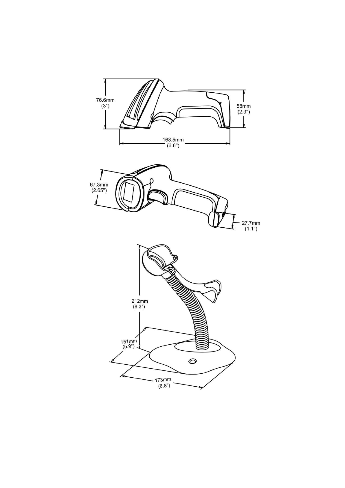
Dimensions
Height ×Width ×Depth:76.6 mm ×67.3 mm ×168.5 mm
Weight
116 g, without cable
Cable
Straight 2.0 m
Connector Type
RJ-45 phone jack connector
Case Material
ABS
Exit Window Material
PC
Indicator
Beeper, LED
Interface Supported
RS-232, USB Keyboard, USB virtual COM
Operating Mode
Hand-held, Auto-detection
Programming Method
Manual (reading special barcode)
Firmware Upgrade
Online
Input Voltage
3.8 –5.5 VDC
Current
85 mA (standby) @ 5 VDC, 265 mA (working) @ 5 VDC
Image Size
640 × 480 pixels
Imager Field of View
Horizontal: 40°, vertical: 30°
Scanning Angle
±60°, ±40°,
360
° (skew, pitch, roll)
Print Contrast
20% minimum reflective difference
Decoding Capability
1D: UPC-A, UPC-E, UPC-E1, EAN-13, EAN-8, ISBN (Bookland EAN),
ISSN, Code 39, Code 39 full ASCII, Code 32, Trioptic Code 39,
Interleaved 2 of 5, Industrial 2 of 5 (Discrete 2 of 5), Matrix 2 of 5, Codabar
(NW7), Code 128, UCC/EAN 128, ISBT 128, Code 93, Code 11 (USD-8),
MSI/Plessey, UK/Plessey, China Post, China Finance, Telepen, GS1
DataBar (formerly RSS) variants
2D: PDF417, QR Code, DataMatrix, Han Xin Code, Aztec Code, MicroQR
Code
Minimum Resolution
5 mil, 1 mil = 0.0254 mm
Decoding Depth
4 mil Code128 (9 chars):
40 mm –70 mm
10 mil Code39 (3 chars):
20 mm –185 mm
13 mil UPC (6 chars):
15 mm –190 mm
20 mil Code39 (1 char):
45 mm –320 mm
6.7 mil PDF417 (20 chars):
28 mm –90 mm
10 mil QR (20 chars):
18 mm –115 mm
10 mil DM (20 chars):
18 mm –115 mm
20 mil QR (20 chars):
20 mm –245 mm
Temperature
-10° to 50°C (14° to 122°F), operating; -20° to 60°C (-4° to 140°F), storage
Humidity
5% to 95% (non-condensing)

2
Safety
EMC: EN55022, EN55024
Electrical Safety: EN60950-1
Photobiological Safety: EN62471:2008
Illumination: 0 ~ 100,000 LUX
ESD Protection: ± 4 KV (contact discharge), ± 8 KV (air discharge)
Drop Resistance: Withstands multiple 2. 0 m (6.6 ft.) drops to concrete
Sealing: IP50

3
1-2
Defaultsettingforeachbarcode
Code type
Read
enable
Check digit
verification
Check digit
transmissio
Min. code
length
Proprietary
code ID
AIM
code ID
UPC-A
√
√
√
(12)2
A
]Em
UPC-E
√
√
√
(8)2
D
]Em
UPC-E1
-
√
√
(8)2
D
]Em
EAN-13
√
√
√
(13)2
A
]Em
EAN-8
√
√
√
(8)2
C
]Em
ISBN (Bookland EAN)
/ ISSN1
√
√
√
(13)2
B
]Em
Code 39
√
-
-
1
M
]Am
Interleaved 2 of 5
√
-
-
6
I
]Im
Industrial 2 of 5
-
-
-
4
H
]Im
Matrix 2 of 5
√
-
-
6
X
]Im
Codabar
√
-
-
4
N
]Fm
Code 128
√
√
-
1
K
]Cm
UCC/EAN 128
√
√
-
1
K
]Cm
ISBT 128
√
√
-
1
K
]Cm
Code 93
√
√
-
1
L
]Gm
Code 11
-
√
-
4
V
-
MSI/Plessey
-
-
-
4
O
]Mm
UK/Plessey
-
√
-
1
U
]Mm
China Post
√
-
-
(11)2
T
]Im
China Finance
-
-
-
(10)2
Y
-
Telepen
√
√
-
1
P
]Em
GS1 DataBar
√
-
-
(16)2
R
]em
GS1 DataBar
Truncated3
√
-
-
(16)2
R
]em
GS1 DataBar Limited
√
-
-
(16)2
R
]em
GS1 DataBar Expanded
√
-
-
1
R
]em
PDF417
√
-
-
-
p
]Lm
DataMatrix
√
-
-
-
d
]dm
QR code
√
-
-
-
q
]Qm
Han Xin Code
-
-
-
-
h
]X0
Aztec Code
-
-
-
-
a
]zm
MicroQR Code
-
-
-
-
q
]Qm
Note: 1The settings for ISBN/ISSN and EAN-13 must be the same except the code ID.
2 Fixed-length barcodes.
3The settings for GS1 DataBar Truncated and GS1 DataBar must be the same.
4
2
Get started
2-1 Dimensions
5
2-2
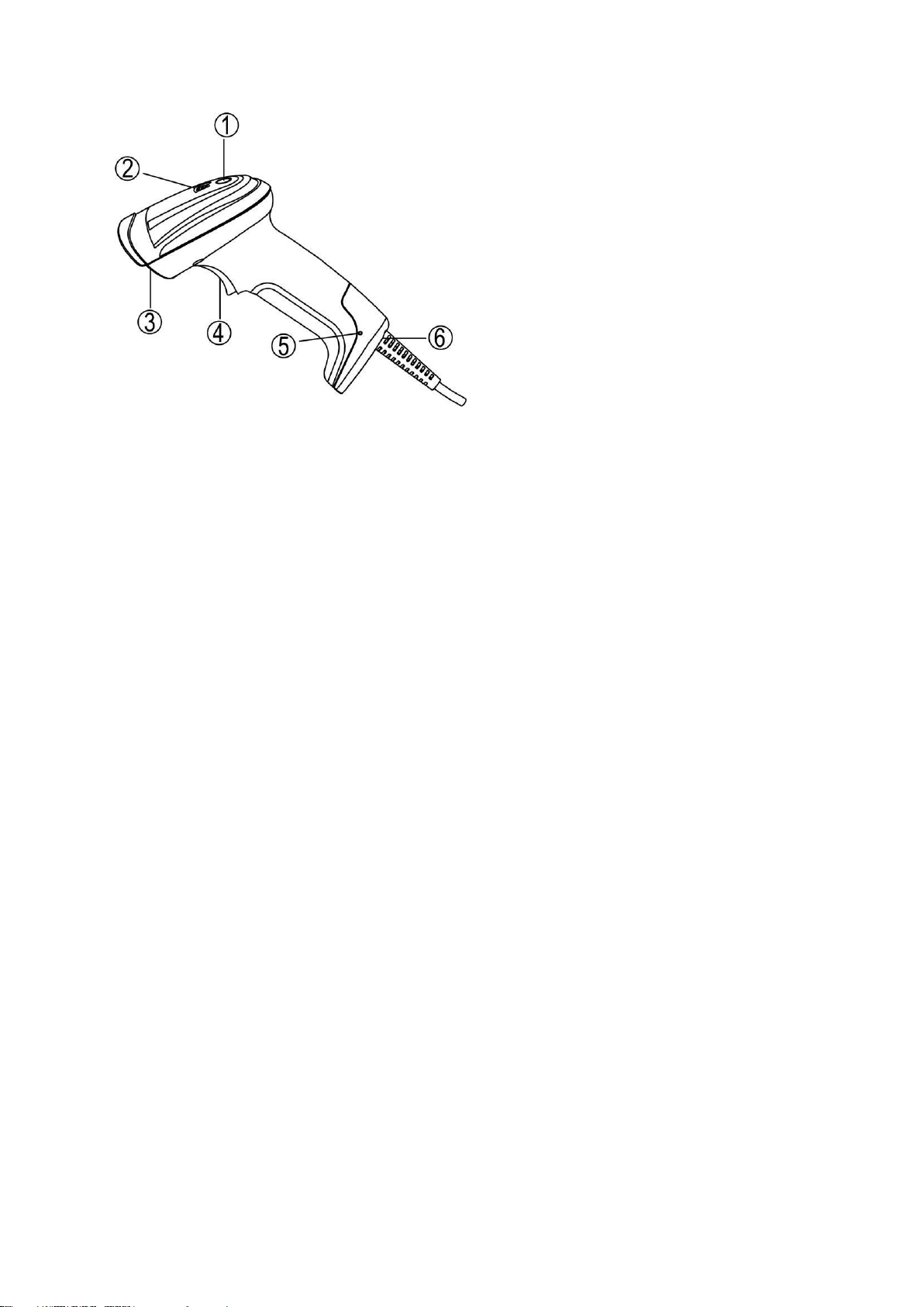
Parts of the scanner
Figure 2-1
① LED
② Beeper
③ Scan window
④ Trigger
⑤ Release-hole of the cable
⑥ Cable interface port
6
2-3
Cable connector pin-outs descriptions
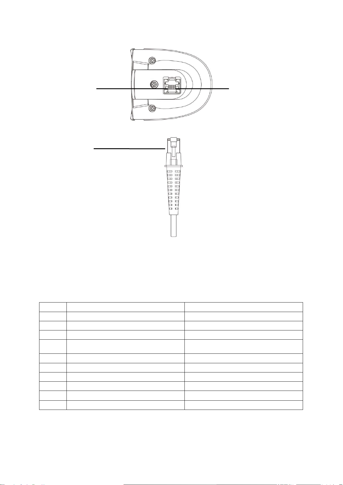
The scanner provides a RJ-45 cable connector.
Pin 1
Cable connector
The pin-outs descriptions in Table 2-1 apply to the cable connector on the scanner and are for reference
only.
Table 2-1 Cable connector pin-outs descriptions
Pin
RS232
USB
1
Power (+5V)
Power (+5V)
2
Reserved
Reserved
3
Ground
Ground
4
+3.3V
( for interface auto selection purpose)
Ground
(for interface auto selection purpose)
5
TxD
Reserved
6
RxD
Reserved
7
Reserved
Reserved
8
Reserved
Reserved
9
CTS
D-
10
RTS
D+
Note: Voltage level of all RS232 Pin-outs (RxD, TxD, CTS and RTS) is 0V for logic low and 3.3V for logic
high.
0 Pin 1
Figure 2-2 Cable connector interface pin-outs
7
2-4
Installation and uninstallation of cable
Note:Ifanyofthebelowoperationisincorrect,turnoffthepowerimmediatelyandcheckthescannerfor
anyimproperconnections.Gothroughallstepsagain.
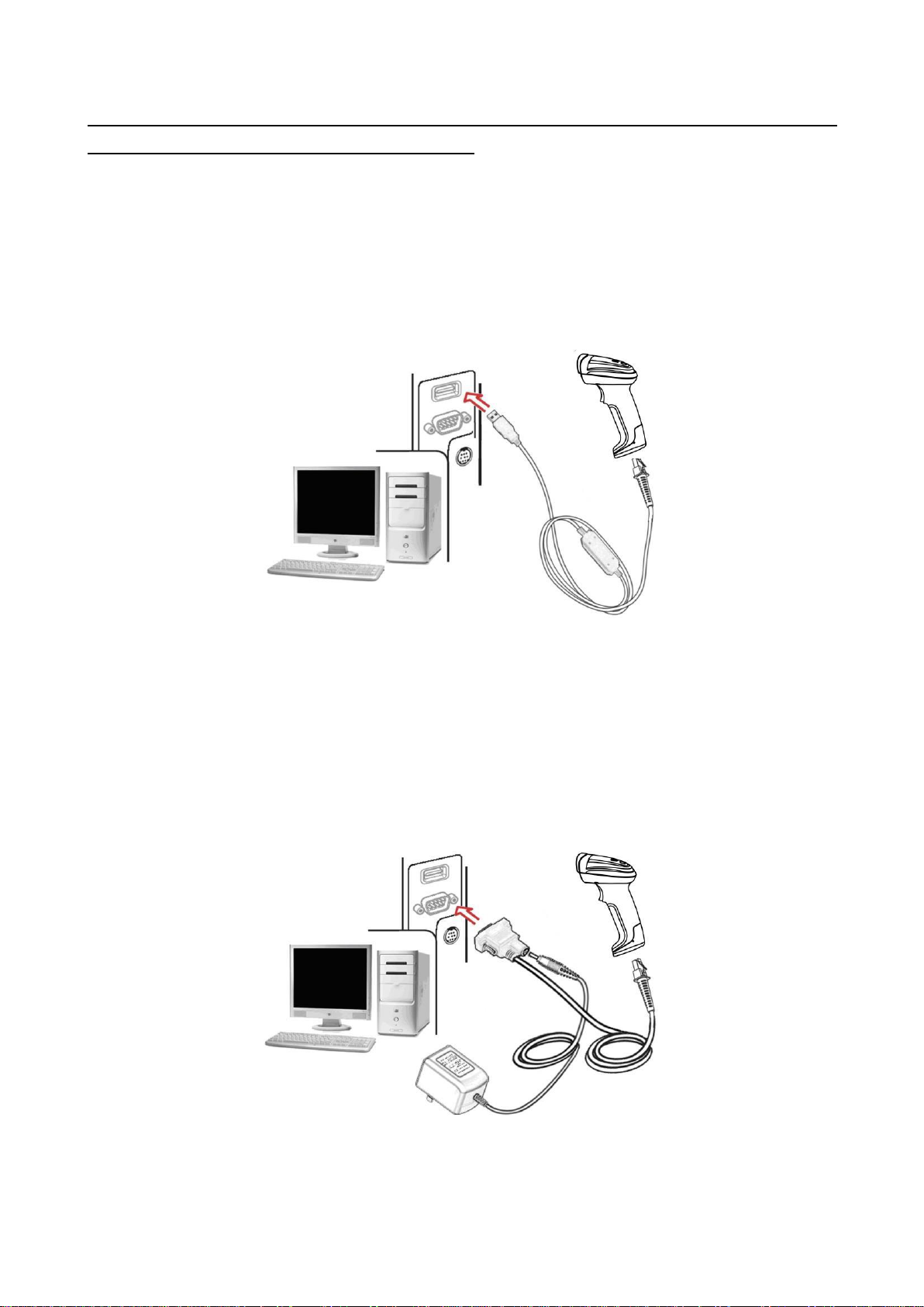
2-4-1
Installation -USB
The scanner attaches directly to a USB host, and is powered by it. No additional power supply is
required.
1. Refer to Figure 2-3, connect the USB interface cable to the bottom of the scanner.
2. Plug the series A connector in the USB host, or an available portof the terminal.
3. Windows will automatically detect the USBdevice.
Figure 2-3
2-4-2
Installation - RS-232
1. Connect the RS-232 interface cable to the bottom of thescanner.
2. Connect the other end of the interface cable to the serial port on the host. Tighten the two screws to
secure the connector to theport.
3. If the host does not have power supply (on PIN 9), connect the external power supply (DC adapter)
to the RS-232cable.
Figure 2-4

8
2-4-3
Uninstallation of cable
Figure 2-5
Remove the interface cable:
1. Find the release-hole.
2. Insert a thin wire into the hole and pull out the cablegently.
2-5 Assembling the stand
Note: The stand is an optional accessory.
1. See the figure above, tighten thescrews.
2. Bend the neck to the desired position forscanning.
3. Screw mounting: Screw one #10 wood screw into each screw-mount-hole until the base of the stand
is secured.
4. Tape mounting: ①Peel the paper liner off one side of each piece of tape and place the sticky
surface over each of the three rectangular tape holders. ②Peel the paper liner off the exposed
sides of each piece of tape and press the stand on a flat surface until it is secure.

9
2-6 Auto-detection
Note: The stand is an optional accessory.
1. To scan a bar code, present the bar code and ensure that the scan angle from the scan window can
cover the symbol.
2. Upon successful decode, the scanner beeps and the LEDlights.
3. When the scanner stops scanning, the present bar code must be removed to active next scanning.
Figure 2-6
The scanner offers 2 methods to enable/ disable Auto-detection quickly.
Method 1
Scan the barcode “EN-AutoDete” on the stand to enable Auto-detection.
Scan the barcode “DIS-AutoDete” on the stand to disable Auto-detection. Note: The
Scanning mode will switch to momentary.
See Figure 2-7.
Method 2
Scan the barcode “%%SWAM” to enable Auto-detection.
Scan the barcode “%%SWLM” to disable Auto-detection. Note: The Scanning mode will
switch to momentary.
See 8 Quick setting to enable/disable Auto-detection.
Figure 2-7
DIS-AutoDete
EN-AutoDete
10
Single-scan setting
9
3 Programming
3-1
Example 1:Single-parameter setting by scanning 1Dbarcodes
Important notes:
1. During the process of programming, LED is lighting to indicate the programming correctness. LED
will go off if any incorrect programming operationperformed.
2. After each successful programming, LED will go off and the scanner will beep twice.
3. Throughout the programming barcode menus, the factory default settings are indicated with
asterisks (*).
Two programming modes have been provided as bellows:
❶Single-scan setting
➢Scan the appropriate (e.g. %0101D00%) according to the user‘s demand.
Example: To set Flow control to be XON/XOFF.
Steps: Scan the following barcode.
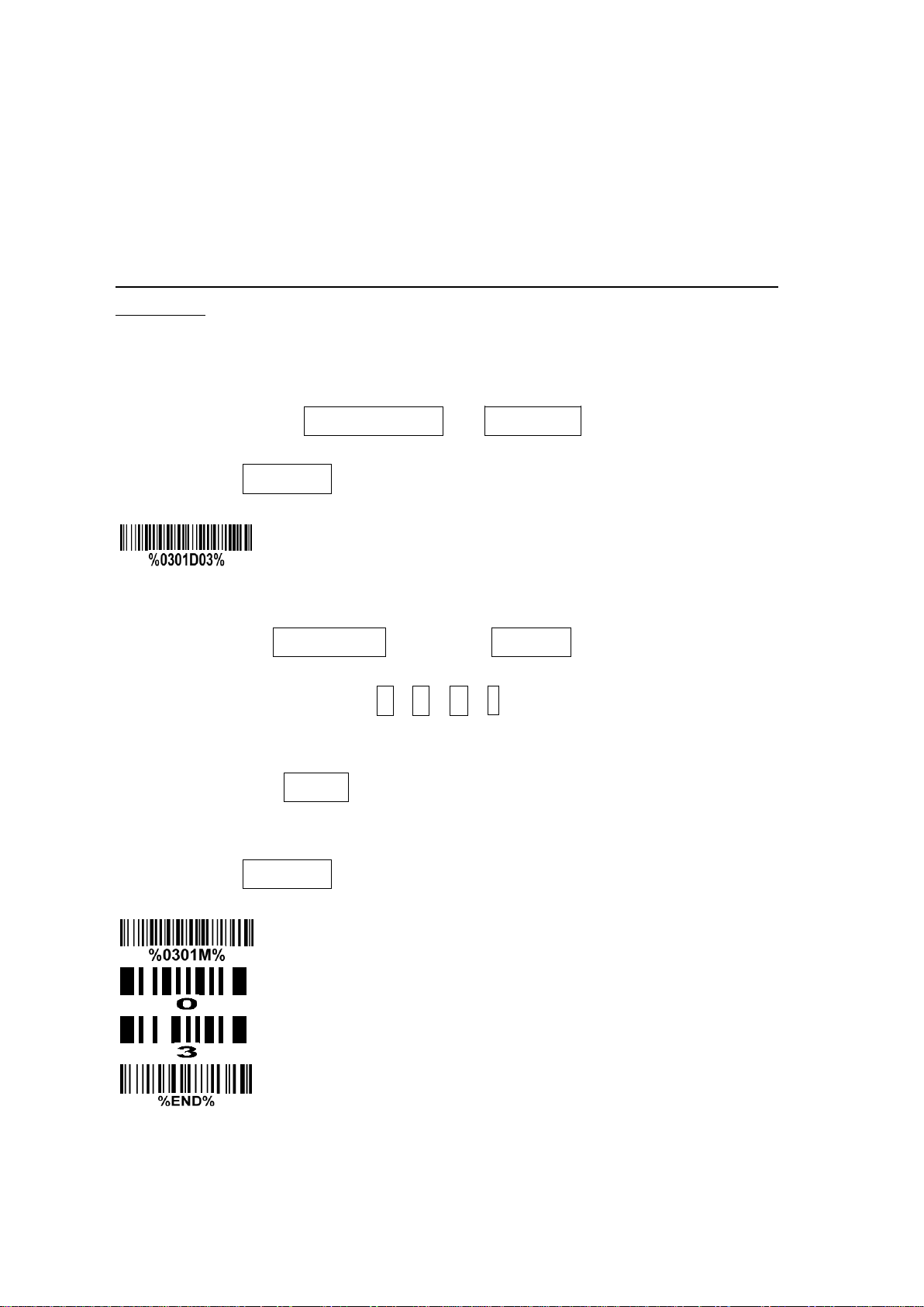
❷Multiple-scan setting
➢Step 1. Scan the
barcode (e.g. %0101M%) according to the user‘s demand.
➢Step 2. To the right of the option barcode, the necessary alphanumeric inputs are listed. Scan
two alphanumeric entries from
barcode.
to or to F, refer to 10 Configuration alphanumeric entry
➢Step 3. Repeat Step 2, if more user parameters input arerequired.
➢Step 4. Scan the
setting part.
Example: To set
barcode, listed on the lower left hand corner of each parameter
to be XON/XOFF.
Steps: Referring to 3-6 RS-232 interface, scan the following barcodes in order.
Option barcode
0
A
%END%
Flow control
11
3-2
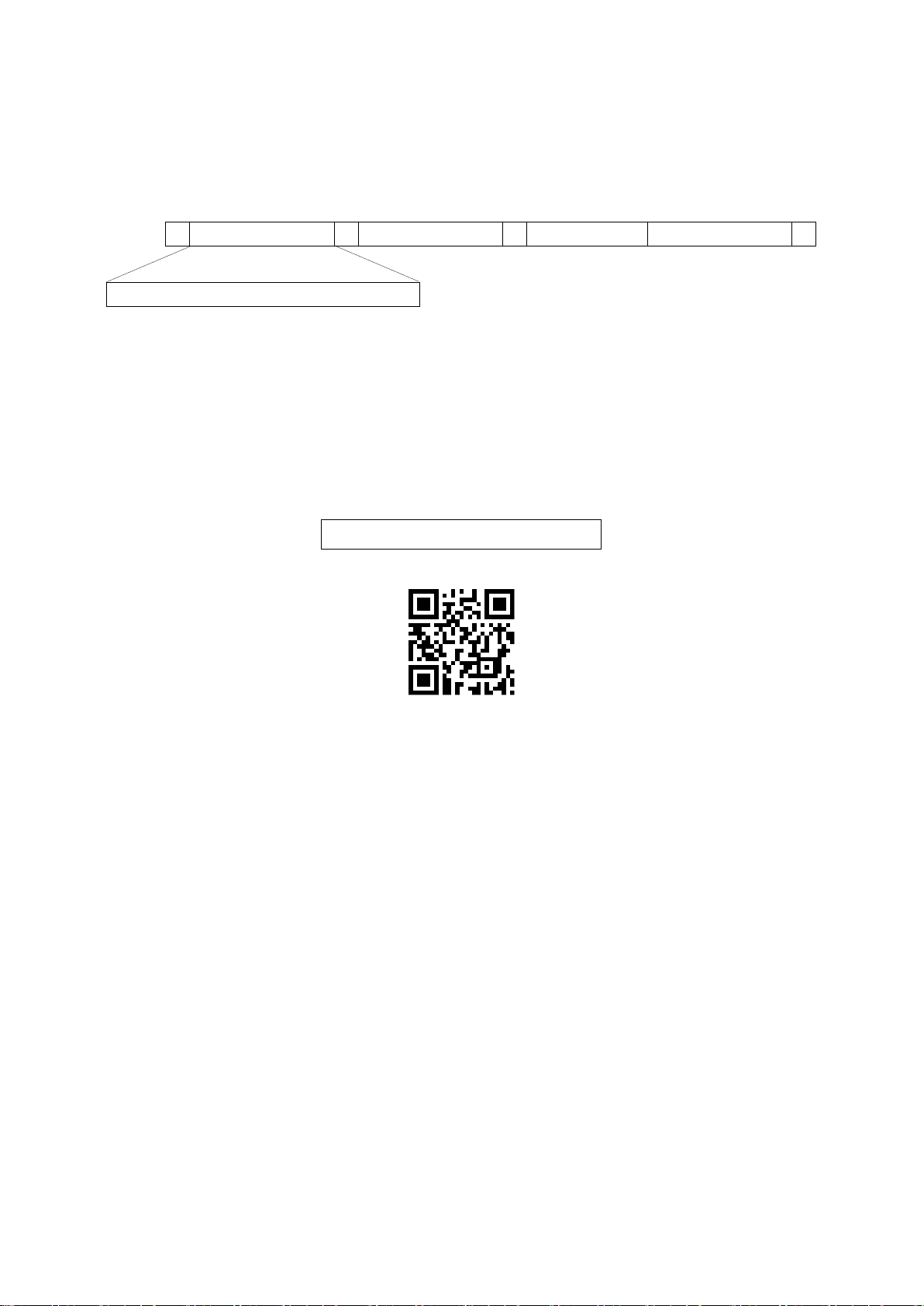
Example 2: Multiple-parameter setting by scanning a QR code barcode
User can customize a QR code to set multiple parameters. The scanner can set multiple parameters by
scanning this single QR code barcode.
1. The data format of the QR code barcode is asfollowing.
%
Parameter set 1
%
Parameter set 2
%
···
Parameter set N
%
Note that:
➢<Option barcode index> means the corresponding 4 digits of Option barcode.
➢<D/H> means “D” or “H” character. D means that the type of alphanumeric entry is decimal; and H
means that the type of alphanumeric entry ishexadecimal.
➢<Alpha. entries> is a character string with various length of 2, 4, or othervalues.
Example: Set 0401->03 (decimal); 8002->0D0A (hexadecimal); 8202->01 (decimal). The customized
QR code barcode contents and symbol are as following.
2. Notes of making QR codebarcode
The model is chosen as M2. Other requirements, e.g. ECC level, Start mode, etc, are not specified.
Other notes
➢The contents of a QR code barcode can include several same <Option barcode index> associated
with same or different <Alpha. entries>. In the case of with different <Alpha. entries>, the latest
<Alpha. entries> is the valid one.
➢If any one of the parameter settings is invalid, the total setting is failed. The invalid setting can be
caused by one of the following problems: invalid <Option barcode index>, invalid type of <D/H>,
invalid type, length or value range of <Alpha. entries>,etc.
<Option barcode index><D/H><Alpha. entries>
%0401D03%8002H0D0A%8202D01%

12
Scan mode
3-3
Operate the scanner by receiving command via UART
Note:
1-
TheinformationinthischapterisprovidedforthescannerwithRS232cableorUSBcable.
2-
IfthescanneriswithUSBcable,thesettingof USBdevicetypemustbesetas “USBvirtualCOM”.
Please refer to 3-7 USB interface.
3-
Pleaseread3-7Scanmode&someglobalsettingsaboutthesettingof
in details.
UART parameter should be set as below:
(1)
Baudrate:9600bps;
(2)
Databits:8bits;
(3)
Stopbit:1bit;
(4)
Paritycheckbit:None;
(5)
Flow control: None.
Guide of control command: all commands are sent by UART
1) Start command: “0x54”(T)
When the scanner received the above command, it will start barcode scanning following the setting of
Scan mode. If the scanner is in the mode of “Auto-detection”, the scanner will have a single scan, then
returns to “Auto-detection” mode.
2) Stop command: “0x50” (P)
If the Scan mode is set as “Alternate continue” or “Continue”, and the scanner received the above
command, it will stop barcode scanning and act as in an idle mode.
3) Restart command: “0x35” (R)
Once the scanner received the above command, it will restart.
Returning message from the scanner
1) A successful decode
Once the scanner successfully decoded a barcode, the scanner will stop scanning and returns the
barcode data to the Host.
2) Not a successful decode
Once the scanner failed to decode a barcode before stopping scanning, the scanner will return a
message to the Host. The message is set as “0x25, 0x25, 0x4E, 0x6F, 0x52, 0x65, 0x61, 0x64”
(%%NoRead).
13
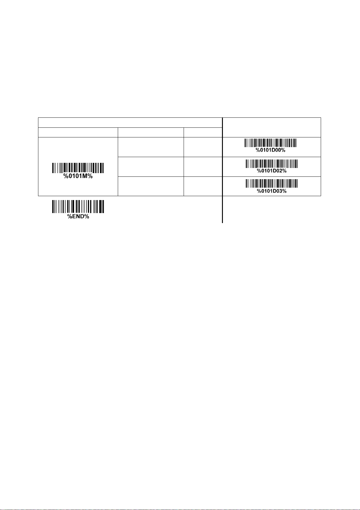
3-4
Interface selection
ThisscannersupportsinterfacessuchasRS-232serialwedgeandUSBinterface.Inmostofthecases,
simplyselectinganappropriatecableprovidedbythemanufacturerwillworkforaspecificinterface.
Interface selection:
Auto detection- By setting this function, the scanner will automatically detect the RS-232 interface or
USB interface for user.
Multiple-scan setting
Single-scan setting
Option barcode
Option
Alpha. entry
Interface selection
Auto detection
(RS-232/USB)
00*
*
RS-232
02
USB
03

14
3-5
RS-232 interface
Host type:
Standard- The scanner is connected to a standard RS-232 interface.
OPOS/JPOS- The scanner is connected to a POS terminal which may be necessary to install the
OPOS/JPOS driver to be compatible with the manufacturer's scanner. The OPOS/JPOS driver is
provided by the scanner manufacturer; please contact the scanner manufacturer for the instruction.
Flow control:
None-The communication only uses TxD and RxD signals without any hardware or software
handshaking protocol.
RTS/CTS- If the scanner wants to send the barcode data to host computer, it will issue the RTS signal
first, wait for the CTS signal from the host computer, and then perform the normal data communication.
If there is no replied CTS signal from the host computer after the timeout duration, the scanner will
issue an error indication. By setting (Host idle: Low RTS) or (Host idle: High RTS), the scanner can be
set to match the Serial Host RTSline.
XON/XOFF- An XOFF character turns the scanner transmission off until the scanner receives an XON
character.
ACK/NAK- After transmitting data, the scanner expects either an ACK (acknowledge) or NAK (not
acknowledge) response from the host. When a NAK is received, the scanner transmits the same data
again and waits for either an ACK or NAK. After three unsuccessful attempts to send data when NAKs
are received, the scanner issues an error indication and discards thedata.
Inter-character delay: This delay is inserted after each data character transmitted.
Response delay: This delay is used for serial communication of the scanner when it waits for a
handshaking acknowledgment from the host.

15
Multiple-scan setting
Single-scan setting
Option barcode
Option
Alpha. entry
Host type
Standard
00*
*
OPOS/JPOS
01
Flow control
None
00*
*
RTS/CTS
(Host idle: Low RTS)
01
RTS/CTS
(Host idle: High RTS)
02
XON/XOFF
03
ACK/NAK
04
Inter-character delay
0 ms
00*
*
5 ms
01
10 ms
02
20 ms
03
40 ms
04
80 ms
05
Response delay
00-99 (100 ms)
00-99
00*
*
Baud rate
300
00
600
01
1200
02
2400
03
4800
04
9600
05*
*
16
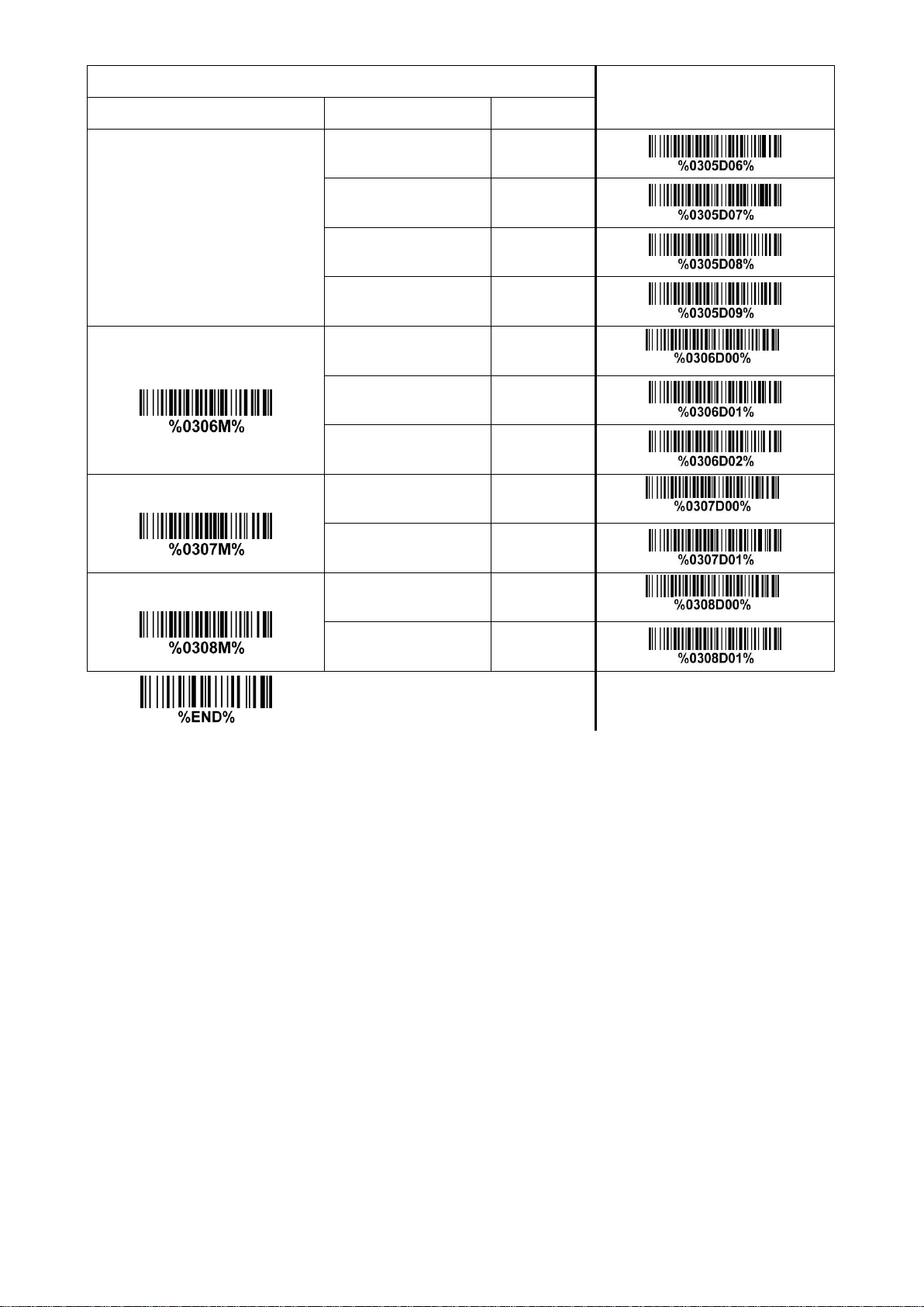
Multiple-scan setting
Single-scan setting
Option barcode
Option
Alpha. entry
19200
06
38400
07
57600
08
115200
09
Parity bit
None
00*
*
Odd
01
Even
02
Data bit
8 bits
00*
*
7 bits
01
Stop bit
One bit
00*
*
Two bits
01
Table of contents
Other ZKTeco Barcode Reader manuals


