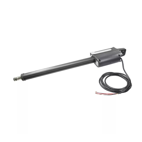
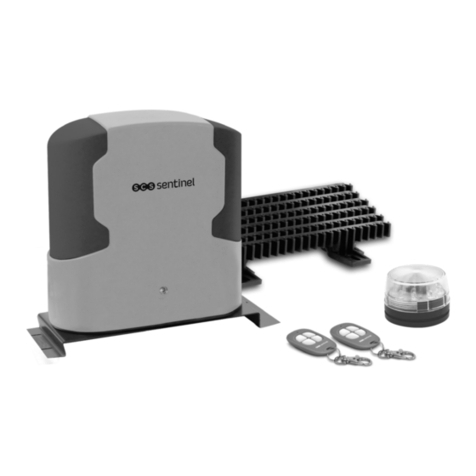
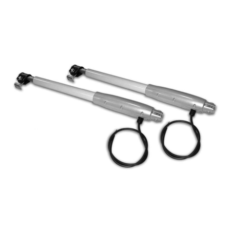
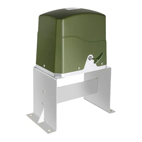
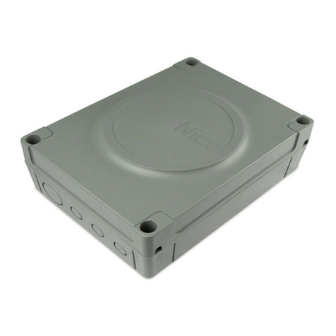
ZKTeco ZK-SW400DC User manual

SBTL500 Series User Manual
P a g e |1Copyright©2020 ZKTECO CO., LTD. All rights reserved.
Thank you for choosing our product. Please read the instructions carefully
before operation. Follow these instructions to ensure that the product is
functioning properly. The images shown in this manual are for illustrative
purposes only.
For further details, please visit our Company’s website
www.zkteco.com.

Swing Gate Opener User Manual
P a g e | 1 Copyright©2022 ZKTECO CO., LTD. All rights reserved.
Copyright © 2022 ZKTECO CO., LTD. All rights reserved.
Without the prior written consent of ZKTeco, no portion of this manual can be copied or forwarded in any
way or form. All parts of this manual belong to ZKTeco and its subsidiaries (hereinafter the "Company" or
"ZKTeco").
Trademark
is a registered trademark of ZKTeco. Other trademarks involved in this manual are owned by
their respective owners.
Disclaimer
This manual contains information on the operation and maintenance of the ZKTeco equipment. The
copyright in all the documents, drawings, etc. in relation to the ZKTeco supplied equipment vests in and is
the property of ZKTeco. The contents hereof should not be used or shared by the receiver with any third
party without express written permission of ZKTeco.
The contents of this manual must be read as a whole before starting the operation and maintenance of the
supplied equipment. If any of the content(s) of the manual seems unclear or incomplete, please contact
ZKTeco before starting the operation and maintenance of the said equipment.
It is an essential pre-requisite for the satisfactory operation and maintenance that the operating and
maintenance personnel are fully familiar with the design and that the said personnel have received
thorough training in operating and maintaining the machine/unit/equipment. It is further essential for the
safe operation of the machine/unit/equipment that personnel has read, understood and followed the
safety instructions contained in the manual.
In case of any conflict between the terms and conditions of this manual and the contract specifications,
drawings, instruction sheets or any other contract-related documents, the contract conditions/documents
shall prevail. The contract specific conditions/documents shall apply in priority.
ZKTeco offers no warranty, guarantee or representation regarding the completeness of any information
contained in this manual or any of the amendments made thereto. ZKTeco does not extend the warranty
of any kind, including, without limitation, any warranty of design, merchantability or fitness for a particular
purpose.
ZKTeco does not assume responsibility for any errors or omissions in the information or documents which
are referenced by or linked to this manual. The entire risk as to the results and performance obtained from
using the information is assumed by the user.
ZKTeco in no event shall be liable to the user or any third party for any incidental, consequential, indirect,
special, or exemplary damages, including, without limitation, loss of business, loss of profits, business
interruption, loss of business information or any pecuniary loss, arising out of, in connection with, or

Swing Gate Opener User Manual
P a g e | 2 Copyright©2022 ZKTECO CO., LTD. All rights reserved.
relating to the use of the information contained in or referenced by this manual, even if ZKTeco has been
advised of the possibility of such damages.
This manual and the information contained therein may include technical, other inaccuracies or
typographical errors. ZKTeco periodically changes the information herein which will be incorporated into
new additions/amendments to the manual. ZKTeco reserves the right to add, delete, amend or modify the
information contained in the manual from time to time in the form of circulars, letters, notes, etc. for better
operation and safety of the machine/unit/equipment. The said additions or amendments are meant for
improvement /better operations of the machine/unit/equipment and such amendments shall not give any
right to claim any compensation or damages under any circumstances.
ZKTeco shall in no way be responsible (I) in case the machine/unit/equipment malfunctions due to any
non-compliance with the instructions contained in this manual (ii) in case of operation of the
machine/unit/equipment beyond the rate limits (iii) in case of operation of the machine and equipment in
conditions different from the prescribed conditions of the manual.
The product will be updated from time to time without prior notice. The latest operation procedures and
relevant documents are available on http://www.zkteco.com
If there is any issue related to the product, please contact us.
ZKTeco Headquarters
Address ZKTeco Industrial Park, No. 32, Industrial Road,
Tangxia Town, Dongguan, China.
Phone +86 769 - 82109991
Fax +86 755 - 89602394
To know more about our global branches, visit www.zkteco.com.

Swing Gate Opener User Manual
P a g e | 3 Copyright©2022 ZKTECO CO., LTD. All rights reserved.
About the Company
ZKTeco is one of the world’s largest manufacturer of RFID and Biometric (Fingerprint, Facial, Finger-vein)
readers. Product offerings include Access Control readers and panels, Near & Far-range Facial Recognition
Cameras, Elevator/floor access controllers, Turnstiles, License Plate Recognition (LPR) gate controllers and
Consumer products including battery-operated fingerprint and face-reader Door Locks. Our security
solutions are multi-lingual and localized in over 18 different languages. At the ZKTeco state-of-the-art
700,000 square foot ISO9001-certified manufacturing facility, we control manufacturing, product design,
component assembly, and logistics/shipping, all under one roof.
The founders of ZKTeco have been determined for independent research and development of biometric
verification procedures and the productization of biometric verification SDK, which was initially widely
applied in PC security and identity authentication fields. With the continuous enhancement of the
development and plenty of market applications, the team has gradually constructed an identity
authentication ecosystem and smart security ecosystem, which are based on biometric verification
techniques. With years of experience in the industrialization of biometric verifications, ZKTeco was
officially established in 2007 and now has been one of the globally leading enterprises in the biometric
verification industry owning various patents and being selected as the National High-tech Enterprise for 6
consecutive years. Its products are protected by intellectual property rights.
About the Manual
This manual introduces the operations of the Swing Gate Opener.
All figures displayed are for illustration purposes only. Figures in this manual may not be exactly consistent
with the actual products.
Features and parameters with ★are not available in all devices.

Swing Gate Opener User Manual
P a g e | 4 Copyright©2022 ZKTECO CO., LTD. All rights reserved.
Document Conventions
Conventions used in this manual are listed below:
GUI Conventions
For Software
Convention
Description
Bold font
Used to identify software interface names e.g. OK,Confirm,Cancel.
>
Multi-level menus are separated by these brackets. For example, File > Create >
Folder.
For Device
Convention
Description
< >
Button or key names for devices. For example, press <OK>.
[ ]
Window names, menu items, data table, and field names are inside square
brackets. For example, pop up the [New User] window.
/
Multi-level menus are separated by forwarding slashes. For example,
[File/Create/Folder].
Symbols
Convention
Description
This represents a note that needs to pay more attention to.
The general information which helps in performing the operations faster.
The information which is significant.
Care is taken to avoid danger or mistakes.
The statement or event that warns of something or that serves as a cautionary
example.

Swing Gate Opener User Manual
P a g e | 5 Copyright©2022 ZKTECO CO., LTD. All rights reserved.
Table of Contents
1 SAFETY INSTRUCTION.......................................................................................................................... 6
2 PARTS LIST.............................................................................................................................................8
PARTS LIST (STANDARD CONFIGURATION) ..........................................................................................................8
PARTS LIST (OPTIONAL) ..................................................................................................................................... 9
3 TECHNICAL PARAMETERS ..................................................................................................................10
4 INSTALLATION .................................................................................................................................... 11
INSTALLATION DRAWING ..................................................................................................................................11
SIZE OF MAIN MACHINE AND MOUNTING BRACKET ..........................................................................................12
4.2.1 SIZE OF MAIN MACHINE..................................................................................................................................................................... 12
4.2.2 SIZE OF MOUNTING BRACKET.........................................................................................................................................................12
INSTALLATION STEPS ........................................................................................................................................13
4.3.1 PREPARATION BEFORE MAIN MACHINE INSTALLATION................................................................................................13
4.3.2 ACCESSORY INSTALLATION..............................................................................................................................................................13
4.3.3 MAIN MACHINE INSTALLATION.....................................................................................................................................................15
4.3.4 SIZE OF CONTROL BOX........................................................................................................................................................................18
4.3.5 LIMIT SWITCH ADJUSTMENT............................................................................................................................................................18
5 WIRING AND DEBUGGING ..................................................................................................................20
WIRING INSTRUCTIONS .....................................................................................................................................20
CONTROL BOARD DRAWING AND INSTRUCTIONS ..............................................................................................21
INPUTS STATUS ................................................................................................................................................ 24
TRAVEL SETTING (VERY IMPORTANT) .......................................................................................................... 24
TRIMMERS SETTING .......................................................................................................................................... 25
LEARNING TRANSMITTER & DELETE TRANSMITTER ............................................................................................25
CONTROL BOARD SETTINGS ............................................................................................................................. 26
5.7.1 BASE MENU.................................................................................................................................................................................................26
5.7.2 ADVANCE MENU......................................................................................................................................................................................28
INFRARED PHOTOCELL CONNECTION (OPTIONAL) .............................................................................................31
SOLAR PANEL CONNECTION (OPTIONAL) ..........................................................................................................32
6 MAINTENANCE ....................................................................................................................................33
7 TROUBLESHOOTING ...........................................................................................................................33

Swing Gate Opener User Manual
P a g e | 6 Copyright©2022 ZKTECO CO., LTD. All rights reserved.
Dear users,
Thank you for choosing this product. Please read the manual carefully before assembling and using
it. Please do not leave out the manual if you send this product to a third party.
1Safety Instruction
Please read this manual carefully before installation, in which involves with important
information about installation, using, maintenance and safety.
Any undefined operations under this manual is not allowed, incorrect using may damage the
product even causing the injuries or property losses.
To consider the possible danger during the installation or using process of swing gate operator,
installation must strictly comply with the construction standard and electrical operating
procedure.
Before installation, please make sure that the power voltage being used matches with the
supply voltage of this product. Please check if the leakage protection switch is installed and the
grounding system is correct.
Please check if additional equipments or materials are required to meet the specific
requirements.
The disposal of packaging material must be complying with the local regulation.
Please do not change any parts except for those defined under this manual. Any undefined
changes may cause the malfunction. Any damages to the product arising therefrom shall be
beyond the liability of the company.
Please do not leak water or any liquid into the controller or any other open devices. Please
disconnect the power immediately if any mentioned cases happened.
Please keep this product away from heat and open fire. Or it may damage the components;
cause failure or other hazards.
Please make sure there are no vehicles, passengers and objects passing through while the
swing gate is moving.
Anti-slip equipment like infrared protection switch must be installed to avoid injuries to person
and property losses. The company shall not be liable for any damage or accident arising
therefrom.

Swing Gate Opener User Manual
P a g e | 7 Copyright©2022 ZKTECO CO., LTD. All rights reserved.
The installation using and maintenance of this product must be carried out by professionals.
Children are not allowed be touch the control devices or remote transmitters.
A warning sign must be placed somewhere on the swing gate according to the national
standard.
Please keep this instruction properly for future reference.

Swing Gate Opener User Manual
P a g e | 8 Copyright©2022 ZKTECO CO., LTD. All rights reserved.
2Parts List
Parts List (Standard Configuration)
No.1
Picture
Name
Quantity
1
Main Machine
2
2
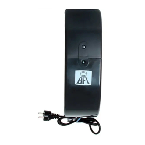
Control Box
1
3
Manual Release Bar
1
4
Remote Control
2
5
Wall Bracket
4
6
Front Mounting Bracket
2
7
Connecting Bracket
2
8
Mounting Screw (short)
2
9
Mounting Screw (long)
2
10
Screw M8 * 25
4
11
Nut M8
6

Swing Gate Opener User Manual
P a g e | 9 Copyright©2022 ZKTECO CO., LTD. All rights reserved.
12
Limit Stopper
1
13
Spring Washer Ø12
2
14
Gasket
2
Parts List (Optional)
No.1
Picture
Name
Quantity
1
Infrared Sensor
1
2
Wireless Keypad
1
3
Alarm Lamp
1
4
Electric Lock
1
5
Storage Battery
2

Swing Gate Opener User Manual
P a g e | 10 Copyright©2022 ZKTECO CO., LTD. All rights reserved.
3Technical Parameters
Model
ZK-SW400DC
Power Supply
220V/50Hz; 110V/60Hz
Motor Power
62W
Gate Moving Speed
22 to 26s/90°
Max. single-leaf weight
400Kg
Max. single-leaf length
3m
Max. piston stroke
45cm
Max. force
3000N
Remote Control Distance
≥30m
Remote Control Mode
Single button mode
Storage Battery (Optional)
DC24V (4.5Ah or 9Ah)
Working Noise
≤60dB
Working Duty
S2, 30min
Recording of up Remote
Controls
25
Remote Frequency
433.92 MHz
Working Temperature
-20°C to +70°C
Package Weight
20Kg

Swing Gate Opener User Manual
P a g e | 11 Copyright©2022 ZKTECO CO., LTD. All rights reserved.
4Installation
The ZK-SW400DC swing gate opener is suitable for single leaf gates weighing less than 400kg and
measuring less than 3m in length. To combine the screw rod transmission, the drive mode uses the
worm and worm gear. For security purposes, this gate opener must be put inside the enclosure or
yard.
Installation Drawing
0
8
5 6
97
4
1 2 3
⑦
①
③
④
⑤
②
⑧
⑥
No.
Description
No.
Description
①
Control Box
⑤
Infrared Sensor (Optional)
②
Gate Opener
⑥
Limit Stopper
③
Gate
⑦
Remote Control
④
Alarm Lamp (Optional)
⑧
Wireless Keypad (Optional)
Figure 1

Swing Gate Opener User Manual
P a g e | 12 Copyright©2022 ZKTECO CO., LTD. All rights reserved.
Size of Main Machine and Mounting Bracket
4.2.1 Size of Main Machine
1450mm
1000mm
106mm
4.2.2 Size of Mounting Bracket
Front mounting bracket Wall bracket
70mm
8.5mm
17.5mm
40mm
2x8.5mm
φ
Figure 2
Figure 3

Swing Gate Opener User Manual
P a g e | 13 Copyright©2022 ZKTECO CO., LTD. All rights reserved.
Installation Steps
4.3.1 Preparation before Main Machine Installation
1. Before installing the door opener, please confirm that the door was installed correctly, please
ensure that the door can be manually operated smoothly, and the door limit stopper can
effectively prevent the door to continue moving.
2. Please leave a 40 to 50 mm gap between the bottom of the door and the ground while
installing the electric lock. If an electric lock is not required, the distance between the door
bottom and the ground should be ≥20mm.
3. The recommended mounting height of two main machines is around 300 to 800 mm above the
ground, and make sure that there are reliable fixed points for mounting brackets.
Cable bury
Please use two PVC pipes to bury the motor and power cables, as well as the control cables,
separately to ensure normal operation of the door opener and to protect the cable from damage.
The motor and power cables are routed via one PVC pipe, while the control cables are routed
through the other.
Mounting brackets fixing
To install the ZK-SW400DC main machines firmly, it is recommended to use the expansion screws to
fix the mounting brackets.
4.3.2 Accessory Installation
Before installing the main machines, please install the wall bracket on the wall first, then fix the
connecting bracket, and finally install the front mounting bracket on the door.
Note: Please detect by gradient before fixing to ensure that the front mounting bracket and the
connecting bracket are in the same level.

Swing Gate Opener User Manual
P a g e | 14 Copyright©2022 ZKTECO CO., LTD. All rights reserved.
Expansion screw Hexagon screw
Nut Nut
Hexagon screw
Nylon gasket
1. The connecting bracket and the wall bracket can be connected according to different
conditions, please refer to the figure 5.
2. Users should prepare power cables for the control box and the main machines by themselves
due to the different installation environment. The control box power supply cable should have
more than 3 cores, whereas the motor cable should have 2. If users need to install external
accessories such as an electric lock, infrared sensor, alarm lamp, or external button switch.
Increase the embedded cables accordingly do make sure the sectional diameter of the electric
lock cable is over 1.5mm2, and the sectional diameter of the other cables is over 0.5mm2. Users
should determine the cable length based on their installation situations.
Note: The outlet on the PVC pipe should be downward to avoid the rainwater flowing into the pipe
along the cable.
3. Please unlock the two main machines before proceeding with the installation. Method of
unlocking: Remove the cover, insert the manual release bar, and rotate the bar until it is
released, as indicated in Figure 6. Then turn the telescopic arm to stretch it easily.
Figure 4
Figure 5

Swing Gate Opener User Manual
P a g e | 15 Copyright©2022 ZKTECO CO., LTD. All rights reserved.
Left engine Right engine
4.3.3 Main Machine Installation
Please refer to Figure 7 to fix the tail of the main machine and the connecting bracket with the
installation screws, and then manually adjust the telescopic arm to the appropriate length. Finally fix
the telescopic arm connector and the front mounting bracket with the installation screws. After
installation, pull the door to confirm that the travel is flexible and not jammed.
Mounting screw (length)
Spring washer
Mounting screw (short)
Nut
gasket
Figure 6
Figure 7

Swing Gate Opener User Manual
P a g e | 16 Copyright©2022 ZKTECO CO., LTD. All rights reserved.
Installation direction: door opens inward
B
C
A
D
L
F
E
Note:Note: TheThe unlimitedunlimited versionversion
mustmust havehave a doordoor limitlimit
stopperstopper installedinstalled
ItIt isis recommendedrecommended toto installinstall withwith a
safetysafety stopperstopper (should(should bebe
preparedprepared byby thethe usersusers themselves)themselves)
A
B
C
D max
L
SIZE (mm)
240
115
15
100°
1400
220
125
25
100°
1440
200
135
35
100°
1420
180
145
45
90°
1420
Table 1 Recommended Installation Position
Figure 8

Swing Gate Opener User Manual
P a g e | 17 Copyright©2022 ZKTECO CO., LTD. All rights reserved.
Installation direction: door opens outward
L
A
B
FE
D
C
Note:Note: TheThe unlimitedunlimited versionversion
mustmust havehave a doordoor limitlimit
stopperstopper installedinstalled
ItIt isis recommendedrecommended toto installinstall withwith a
safetysafety stopperstopper (should(should bebe
preparedprepared byby thethe usersusers themselves)themselves)
A
B
C
D
L
SIZE (mm)
170
170
40
90°
1000
180
170
30
100°
1000
190
170
30
100°
1000
200
180
40
100°
1000
Table 2 Recommended Installation Position
Note: Value B must be close to or equal to value A to reach the best mechanical advantage.
Figure 9

Swing Gate Opener User Manual
P a g e | 18 Copyright©2022 ZKTECO CO., LTD. All rights reserved.
4.3.4 Size of Control Box
4.3.5 Limit Switch Adjustment
TS2TS2 TS3TS3TS1TS1
S.D.S.D. SPE EDSPEED O BSTD.OBSTD.
U2U2
I D 2 1 0 V 1 . 0
ACAC ININ +BATT-+BATT-
M1M1 M2M2
1313 1414 1515 1616 1717 1818 1919 2020 2121 2222
LOCKLOCK BLKBLK
OUTOUT LPWLPW
+24+24 + 12+12 COMCOM
SPDSPD
PHPH
STPSTP
STRSTR
PHSPHS
EOEO
ECEC
121211111010987654321
U1U1
M2M2
TransformerTransformer
240/22V240/22V 120VA120VA
230VAc230VAc
FUSEFUSE 15A15A
BatteryBattery
24V(1)24V(1)
12V(1)12V(1)
+SOLAR-+SOLAR-
(1)just(1)just a batterybattery voltagevoltage cancan
bebe connectedconnected atat once,once, oror 12V12V oror 24V24V
OutOut 24 /12VDC2 4/12VDC 250 mA2 50mA
ElectricElectr ic LockLock BlinkerBlinker M1M1
Please refer to figure 11 to adjust the limit switch. Remove the rubber block first from the end cover,
then pull the inside plastic piece out.
TS2TS2 TS3TS3TS1TS1
S.D.S.D. SPEEDSPEED OBSTD.OBSTD.
U2U2
I D 2 1 0 V 1 . 0
ACAC ININ +BATT-+BATT-
M1M1 M2M2
1313 1414 1515 1616 1717 1818 1919 2020 2121 2222
LOCKLOCK BLKBLK
OUTOUT LPWLPW
+24+24 +12+12 COMCOM
SPDS PD
PHPH
STPSTP
STRSTR
PHSP HS
EOEO
ECEC
12121111101098
7
6
54
321
U1U1
+SOLAR-+SOLAR-
Figure 10
Control box without built-in battery
Control box with built-in battery
Figure 11
Figure 12

Swing Gate Opener User Manual
P a g e | 19 Copyright©2022 ZKTECO CO., LTD. All rights reserved.
Loosen the fastening screws first, then change the open and shut limit positions separately to learn
the travel. If the gate cannot be closed in position, please move the close limit position to direction
A; If the gate is over closed, please move the close limit position to direction B; If the gate cannot be
opened in position, please move the open limit position to direction B; If the gate is over opened,
please move the open limit position to direction A.
For the first few times, you can adjust it greatly to approximately determine the open and close limit
position. And then adjust it slightly to finally decide the open and close limit position accurately.
Please remember to fasten all screws after adjustment, insert the plastic pieces to their original place
and press with the rubber block.
Warning
To ensure safety and protect the machines, please install a gate stopper at the open limit
position when the door opens outward to prevent the gate from running over its travel.
Meanwhile, to enable the 2 swings to close to their accurate limit position, please install a limit
stopper at the close limit position (as shown in figure 9). Similarly, when the door opens inward,
please install a limit stopper at the close limit position (as shown in figure 8).
Before installing the main machine, please make sure that the main machine and components
are in good mechanical performance and the door can be manually operated flexibly.
One control unit can optionally drive one main machine or two main machines.
Earth leakage circuit breaker must be installed on where the gate movement can be seen, and
the minimum mounting height for the control box should be over 1.5m to avoid being touched
by kids.
After installation, please check whether the mechanical property is good or not, whether gate
movement is flexible or not after unlocking, and whether the infrared sensor (optional) is
installed correctly and effectively.
Table of contents
