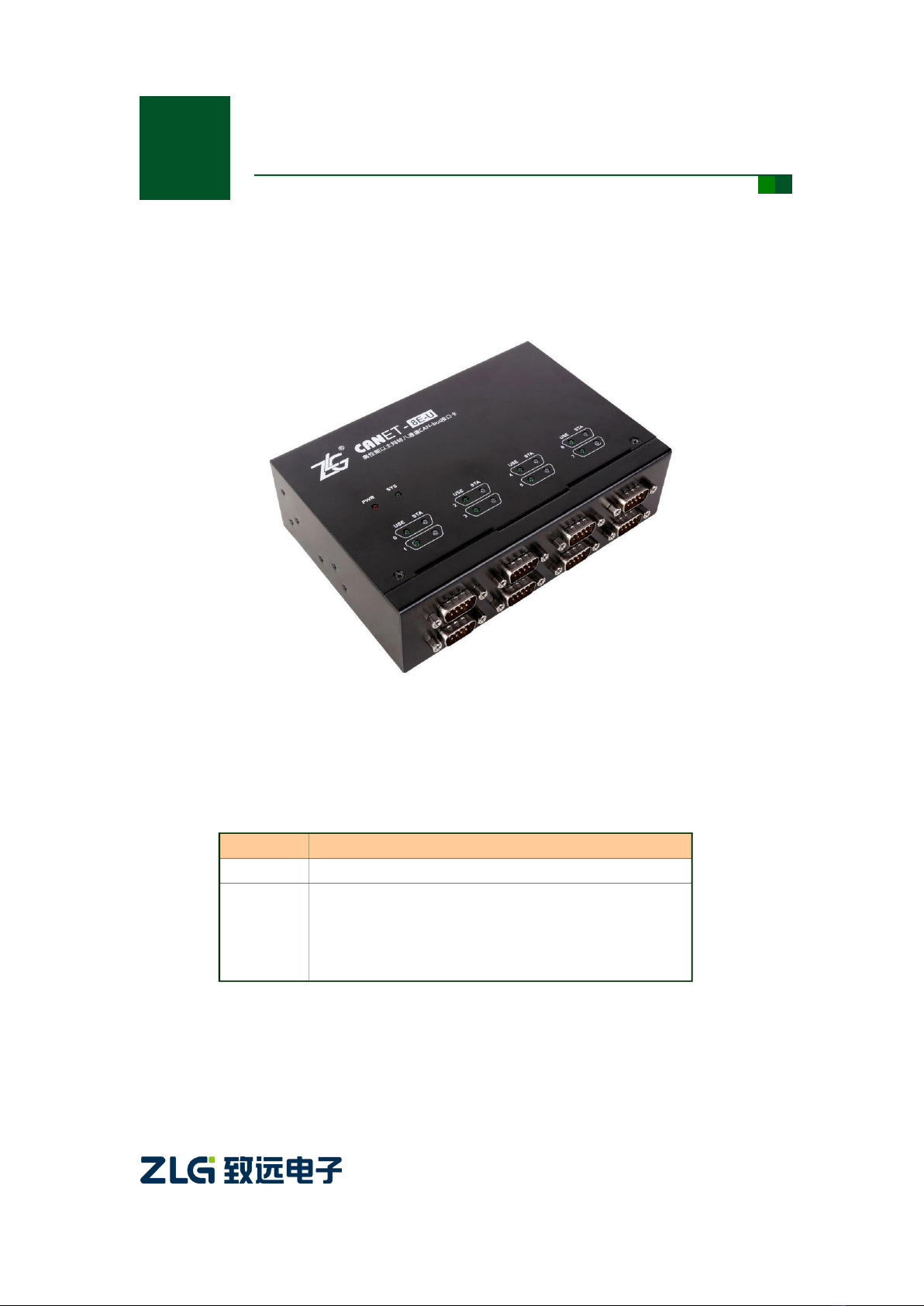
ZLG CANET-8E-U User manual

Product User Manual
CANET-8E-U
High-Performance Eight-Channel Ethernet to CAN Converter
User Manual
UM01010101 V1.03 Date: 2020/11/17
Category
Contents
Keywords
CAN-bus Ethernet Eight-Channel CAN
Description
The CANET-8E-U high-performance eight-channel
Ethernet to CAN converter is a derivative product on the
new generation hardware and software platform, which
improves the communication flow and system reliability.
©2021 Guangzhou ZLG Electronics Technology Co.,Ltd.

CANFDNET-400U
High-Performance Four-Channel CANFD Bus-to-Ethernet Converter User Manual
©2021 Guangzhou ZLG Electronics Technology Co.,Ltd.
i
User Manual
Revision History
Version
Date
Description
V0.90
August 23, 2017
Created
V1.00
August 29, 2017
Improved the document
V1.01
October 9, 2017
Fixed bugs
V1.02
March 12, 2019
Updated the document header and footer and "Sales and
Service Network" content and added the "Disclaimer" content
V1.03
November 17, 2020
Added 1000M network port pin definition

CANFDNET-400U
High-Performance Four-Channel CANFD Bus-to-Ethernet Converter User Manual
©2021 Guangzhou ZLG Electronics Technology Co.,Ltd.
1
User Manual
Contents
1. Functions .....................................................................................................1
1.1 Overview.................................................................................................................1
1.2 Features..................................................................................................................2
1.2.1 Powerful hardware.......................................................................................2
1.2.2 Perfect functions ..........................................................................................2
1.3 Specifications .........................................................................................................3
1.3.1 LAN...............................................................................................................3
1.3.2 CAN..............................................................................................................3
1.3.3 Software Features........................................................................................3
1.3.4 EMC Characteristics ....................................................................................3
1.3.5 Electrical Parameters...................................................................................3
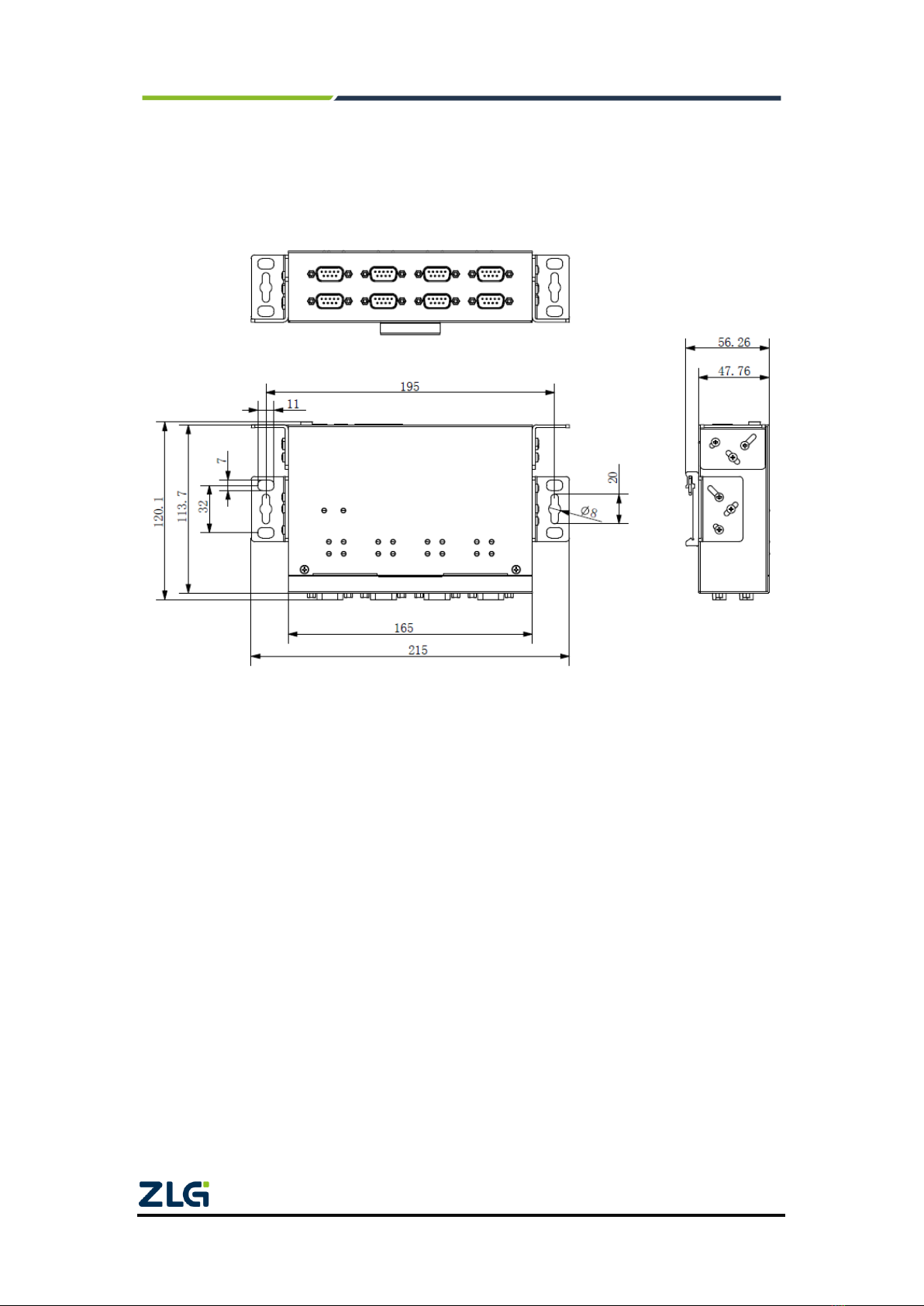
1.4 Mechanical Dimensions .........................................................................................5
2. Hardware Interfaces.....................................................................................6
2.1 Appearance ............................................................................................................6
2.2 Power Interfaces.....................................................................................................7
2.3 Ethernet Interface...................................................................................................7
2.4 Device Restart and Default Restoration.................................................................7
2.5 Terminal Resistance DIP Switch ............................................................................8
2.6 CAN Communication Interface...............................................................................9
2.7 Signal Indicators...................................................................................................10
3. Hardware Connection................................................................................11
4. Working Modes..........................................................................................12
4.1 TCP Server Mode.................................................................................................12
4.2 TCP Client Mode ..................................................................................................13
4.3 UDP Mode............................................................................................................14
5. Quick Instructions ......................................................................................15
5.1 Default Settings of the Device IPAddress ...........................................................15
5.2 Obtaining the Device IPAddress..........................................................................15
5.3 PC and Device Network Segment Detection.......................................................17
5.3.1 Windows98/ME Network Settings..............................................................17
5.3.2 Windows 2000/XP Network Settings .........................................................19
5.4 CANET-8E-U and USBCAN Interface Card Communication...............................22
6. ZNetCom Software Configuration..............................................................27
6.1 Installing Configuration Software .........................................................................27
6.2 Obtaining Device Configurations..........................................................................28
6.3 Modifying Device Configurations..........................................................................31
6.4 Configuration Parameters ....................................................................................31
6.5 Saving Restored Settings.....................................................................................38
6.5.1 Saving Settings..........................................................................................38
6.5.2 Restoring Settings......................................................................................38
6.6 Upgrading Firmware.............................................................................................39

CANFDNET-400U
High-Performance Four-Channel CANFD Bus-to-Ethernet Converter User Manual
©2021 Guangzhou ZLG Electronics Technology Co.,Ltd.
2
User Manual
7. Providing the Secondary Development Guidance for the Host Computer .42
7.1 Preliminary Preparation for CAN Card Interface Function Development............42
7.2 Interface Library Function Usage Process...........................................................44
8. Appendix....................................................................................................45
8.1 CANET-8E-U Working Port Data Conversion Format..........................................45
8.2 CANET-8E-U Data Conversion Format of TCP Notification Port in CAN Port
State............................................................................................................................47
9. Disclaimer..................................................................................................48

CANFDNET-400U
High-Performance Four-Channel CANFD Bus-to-Ethernet Converter User Manual
©2021 Guangzhou ZLG Electronics Technology Co.,Ltd.
1
User Manual
1. Functions
1.1 Overview
The CANET-8E-U is a high-performance industrial-grade Ethernet CAN-bus data
conversion device developed by Guangzhou ZLG Electronics Co., Ltd. It integrates eight
CAN-bus interfaces, one Ethernet interface and TCP/IP protocol stack, which allows you
to easily interconnect CAN-bus network and Ethernet, and further expand the scope of
CAN-bus network.
The CANET-8E-U is an industrial grade product and works in the temperature range
of -40°C to +85°C . It has 100M/1000M adaptive Ethernet interface. The highest baud rate
of CAN port communication is 1 Mbps. It has various working modes such as TCP Server,
TCP Client, and UDP. Each CAN port supports multiple TCP or UDP connections. You can
flexibly set configuration parameters by using the configuration software. The following
figure shows a typical application.
Figure 1.1 CANET typical application

CANFDNET-400U
High-Performance Four-Channel CANFD Bus-to-Ethernet Converter User Manual
©2021 Guangzhou ZLG Electronics Technology Co.,Ltd.
2
User Manual
1.2 Features
1.2.1 Powerful Hardware
High-speed 800 MHz main-frequency 32-bit processor;
100M/1000M self-applicable Ethernet interface, 2 kV electromagnetic isolation;
Eight CAN ports, 2.5 kVDC withstand voltage isolation;
CAN port baud rate 5k-1,000kbps can be set arbitrarily;
Embedded hardware watchdog timer;
Power supply voltage range 9-48 V DC;
Operating temperature: -40°C to +85°C;
Humidity: 5%-95% RH, no condensation;
Rugged metal housing, SECC metal (1.1 mm);
Designed specifically for industrial environments.
1.2.2 Perfect Functions
Static or dynamic IP acquisition;
Heartbeat and timeout disconnection;
The working port is fixed, and the destination IP address and port can be set;
After the network is disconnected, the connection resources are automatically
restored, and the TCP connection is established reliably;
Manage one CAN port while satisfying six groups of users;
In UDP mode, each CAN port supports six groups of target IP segments. Multiple
users can manage a CAN device at the same time;
Supported protocols include ETHERNET, ARP, IP, ICMP, UDP, DHCP, DNS, and
TCP;
Compatible with SOCKET working methods (TCP Server, TCP Client, UDP). The
writing of the host computer communication software follows the standard
SOCKET rules;
Two-way transparent transmission of CAN data and Ethernet data (For the
format, see Appendix 8.1);
Flexible CAN port data framing settings meet various subcontracting needs;
Each CAN port can be configured into different working modes, which can be
flexibly used in various fields;
Each CAN port opens a diagnostic port, and the host computer can obtain the
error status of the corresponding CAN port by connecting this port;
The operating parameters can be configured using the Windows configuration
software;
Provide Windows platform configuration software function library for free,
including easy-to-use API function library, which helps users write their own
configuration software;
Support local system firmware upgrade.

CANFDNET-400U
High-Performance Four-Channel CANFD Bus-to-Ethernet Converter User Manual
©2021 Guangzhou ZLG Electronics Technology Co.,Ltd.
3
User Manual
1.3 Specifications
1.3.1 LAN
100M/1000M Ethernet, RJ45 interface, 2 kV electromagnetic isolation.
1.3.2 CAN
Number of CAN ports: 8
Interface type: DB9 (male)
Signal cable: CAN0H-CAN0L, CAN7H-CAN7L
Baud rate: 5 k-1,000 kbps
1.3.3 Software Features
Supported TCP/IP protocols: ETHERNET, ARP, IP, ICMP, UDP, TCP, DHCP,
DNS
Communication software: CANtest test tool (V2.61), TCP/UDP test tool
Configuration software: ZNetCom (V3.33 or later)
1.3.4 EMC Characteristics
Interface
Test Item
Testing
Standards
Test
Voltage
Test
Result
Remarks
Power
interface
Electrostatic test
IEC61000-4-2
±6kV
A
Contact discharge
±8kV
Air discharge
Group pulse test
IEC61000-4-4
±2kV
A
Capacitive coupling
Surge test
IEC61000-4-5
±1kV
A
Differential mode
±2kV
A
Common mode
Ethernet
interface
Electrostatic test
IEC61000-4-2
±6kV
A
Contact discharge
±8kV
Air discharge
CAN
interface
Electrostatic test
IEC61000-4-2
±6kV
A
Contact discharge
±8kV
Air discharge
Group pulse test
IEC61000-4-4
±2kV
A
Capacitive coupling
clip
Surge test
IEC61000-4-5
±2kV
A
Common mode
Buttons,
indicators
Electrostatic test
IEC61000-4-2
±8kV
A
Air discharge
1.3.5 Electrical Parameters
Unless otherwise specified, the parameters listed in the following table refer to the
value at Tamb=25°C .
Parameter Name
Symbol
Rating
Unit
Power voltage
VCC
+12
V
Power consumption
PM
4000
mW

CANFDNET-400U
High-Performance Four-Channel CANFD Bus-to-Ethernet Converter User Manual
©2021 Guangzhou ZLG Electronics Technology Co.,Ltd.
4
User Manual
Operating ambient temperature
Tamb
-40°C ~85°C
°C
Storage temperature
Tstg
-40°C ~85°C
°C

CANFDNET-400U
High-Performance Four-Channel CANFD Bus-to-Ethernet Converter User Manual
©2021 Guangzhou ZLG Electronics Technology Co.,Ltd.
5
User Manual
1.4 Mechanical Dimensions
To install CANET-8E-U, refer to the appearance and mechanical dimensions (unit:
mm) provided in Figure 1.2. The figure specifies the length, width, height, and part of the
mechanical structure of the product.
Figure 1.2 CANET-8E-U installation dimensions

CANFDNET-400U
High-Performance Four-Channel CANFD Bus-to-Ethernet Converter User Manual
©2021 Guangzhou ZLG Electronics Technology Co.,Ltd.
6
User Manual
2. Hardware Interfaces
This chapter describes the hardware interfaces of CANET-8E-U.
2.1 Appearance
Figure 2.1 CANET-8E-U appearance

CANFDNET-400U
High-Performance Four-Channel CANFD Bus-to-Ethernet Converter User Manual
©2021 Guangzhou ZLG Electronics Technology Co.,Ltd.
7
User Manual
2.2 Power Interfaces
CANET-8E-U uses 9-48 V DC power supply. Two power input terminals are provided:
3Pin plug-in terminal;
DC JACK socket (inside positive, outside negative).
Note: The power cable can be connected to either terminal, but not both power terminals at the
same time.
The plug-in terminals are M3.5 terminal screws. Use crimp terminals for wiring. VIN is
connected to the positive pole of the power supply, and GND is connected to the negative
pole of the power supply. If the power is fully connected, the "PWR" indicator will remain
red. The power port of CANET-8E-U also has a ground terminal, which is used to connect
to the ground for static electricity or surge discharge.
Figure 2.2 Power interface signals
2.3 Ethernet Interface
CANET-8E-U has two Ethernet (RJ45) ports, as shown in Figure 2.3. Table 2.1 lists
the definition of each pin.
Figure 2.3 Appearance of RJ45 interface
Table 2.1 RJ45 pin definition
Pin
100M signal
1000M signal
1
TX+
DA+
2
Tx-
DA-
3
Rx+
DB+
4
-
DC+
5
-
DC-
6
Rx-
DB-
7
-
DD+
8
-
DD-
2.4 Device Restart and Default Restoration
Short-press RST (less than 2s). CANET-8E-U enters the restart state.
Long-press RST (longer than 5s). CANET-8E-U restores factory settings.

CANFDNET-400U
High-Performance Four-Channel CANFD Bus-to-Ethernet Converter User Manual
©2021 Guangzhou ZLG Electronics Technology Co.,Ltd.
8
User Manual
2.5 Terminal Resistance DIP Switch
To enhance the reliability of CAN communication, the two endpoints of the CAN bus
network usually need to be equipped with terminal matching resistors. The value of the
terminal resistor is determined by the characteristic impedance of the transmission cable.
For example, if the characteristic impedance of the twisted pair is 120 ohm, the two
endpoints on the bus should also integrate 120-ohm termination resistors. The
CANET-8E-U interface card adopts CTM8251KT transceiver. If other nodes on the
network use different transceivers, the terminal resistance must be calculated separately.
The function of the CAN bus terminal resistor:
Improve the anti-interference ability to ensure that the bus quickly enters the
recessive state;
Improve signal quality.
CANET-8E-U uses a mechanical switch to select a terminal resistor. The DIP switch
is at the bottom of the device, as shown in Table 2.2. The device's DIP switch is "ON" by
default; that is, the default access terminal resistance is 120 ohm.
Table 2.2 CANET-8E-U terminal resistance DIP switch
Description
DIP switch
The corresponding CAN channel connects
to 120 ohm
or
The corresponding CAN channel has no
access resistance

CANFDNET-400U
High-Performance Four-Channel CANFD Bus-to-Ethernet Converter User Manual
©2021 Guangzhou ZLG Electronics Technology Co.,Ltd.
9
User Manual
2.6 CAN Communication Interface
The commonly used electrical connectors for CAN-bus communication interface are:
DB9 socket, OPEN5 socket, OPEN3 socket, etc. The CANET-8E-U interface card
integrates 1 to 8 CAN channels, which can be used to connect CAN-bus network or
devices equipped with CAN-bus interface. The CAN-bus channel of CANET-8E-U adopts
the standard male DB9 socket. Table 2.3 lists the DB9 pin definitions.
Table 2.3 DB9 pin socket pin signal definitions of CANET-8E-U
Pin
Signal
Description
Function
1
NC
Unused
2
CAN_L
CAN_L signal cable
3
CGND
Reference ground
4
NC
Unused
5
CAN_SHIELD
Shielded cable
6
CGND
Reference ground
7
CAN_H
CAN_H signal cable
8
NC
Unused
9
NC
Unused
In some applications, some CAN-bus interfaces are OPEN-5 interfaces, and
CANET-8E-U comes standard with eight DB9-to-OPEN5 connectors. Table 2.4 describes
the signal definitions for the OPEN5 socket.
Table 2.4 Definition of accessories DB9 to OPEN5 signal
Pin
Signal
Description
Picture
1
V-
Reference
ground
2
CAN_L
CAN_L signal
cable
3
CAN_SHIELD
Shielded cable
4
CAN_H
CAN_H signal
cable
5
V+
Unused

CANFDNET-400U
High-Performance Four-Channel CANFD Bus-to-Ethernet Converter User Manual
©2021 Guangzhou ZLG Electronics Technology Co.,Ltd.
10
User Manual
2.7 Signal Indicators
The CANET-8E-U interface card has a power indicator PWR and a SYS indicator.
Each corresponding channel has two CAN interface status indicators to indicate the
operating status of the channel. Table 2.5 describes the indicators.
Table 2.5 Indicators of the CANET-8E-U interface card
Indicator
Status
Description
PWR
Red
Device powered on
SYS
Off
CANET device initialization has not completed
Green flashing
The CANET device is initialized and is running properly
USE
Green on
No meaning
STA
Off
The corresponding channel has no message transmission
Green flashing
The corresponding channel is transmitting packets
Red flashing
Bus error

CANFDNET-400U
High-Performance Four-Channel CANFD Bus-to-Ethernet Converter User Manual
©2021 Guangzhou ZLG Electronics Technology Co.,Ltd.
11
User Manual
3. Hardware Connection
In general, the CANET-8E-U can be used to bridge CAN_Bus and Ethernet, which
interconnects your CAN_Bus and Ethernet and allows PCs to control the devices on the
your CAN_Bus network through the Ethernet. Figure 3.1 shows a typical application.
Figure 3.1 Typical application of the CANET device
Simple tests can be performed using the CANTest software.

CANFDNET-400U
High-Performance Four-Channel CANFD Bus-to-Ethernet Converter User Manual
©2021 Guangzhou ZLG Electronics Technology Co.,Ltd.
12
User Manual
4. Working Modes
The CANET-8E-U has three working modes, which are described as follows:
4.1 TCP Server Mode
Figure 4.1 TCP Sever mode communication
In TCP Server mode, CANET-8E-U will not actively connect to other devices. It
always waits for the connection of the client (TCP Client), and can perform two-way data
communication after establishing a TCP connection with the client. Figure 4.1 shows the
communication establishment process.
Tip: In this mode, the client connects to the CANET-8E-U device over the "working
port (see Table 6.1)" corresponding to the CAN port.

CANFDNET-400U
High-Performance Four-Channel CANFD Bus-to-Ethernet Converter User Manual
©2021 Guangzhou ZLG Electronics Technology Co.,Ltd.
13
User Manual
4.2 TCP Client Mode
Figure 4.2 TCP Client mode communication
In TCP Client mode, the CANET-8E-U will actively connect to the preset TCP server.
If the connection fails, the client continuously tries to establish a connection with the TCP
server based on the preset connection conditions. After establishing a TCP connection
with the TCP server, two-way data communication can be carried out. 错误!未找到引用源。
shows the communication establishment process.
Tip: In this mode, the TCP server IP address is determined by "destination IP (see
Table 6.1)"; the TCP server port is determined by "destination port (see Table 6.1)".
There are six groups of valid "Destination Port" and "Destination IP". The device will
connect to the TCP server specified by the six groups of parameters in turn based on
the preset number of connections until the connection is successful.

CANFDNET-400U
High-Performance Four-Channel CANFD Bus-to-Ethernet Converter User Manual
©2021 Guangzhou ZLG Electronics Technology Co.,Ltd.
14
User Manual
4.3 UDP Mode
Figure 4.3 UDP mode communication
In UDP mode, the UDP protocol is used for data communication. UDP is a
non-connection-based communication method. It cannot guarantee that the data packets
sent to the target host will be received correctly. Therefore, in the scenarios with high
reliability requirements, the upper-layer communication protocol must be used to ensure
that the data is correct; however, because UDP is a simple communication method, it will
not increase too much additional communication volume, and can provide a higher
communication speed than the TCP method to ensure the real-time transmission of data
packets. In fact, when the network environment is simple and the network communication
load is not too large, the UDP working method is not error prone. The devices working in
this mode are equal, and there is no server and client. Figure 4.3 shows the
communication process.
Tip: In this mode, CANET-8E-U uses "working port (see Table 6.1)" to receive UDP
packets sent by user equipment; the data received by the CAN port of the
CANET-8E-U device will be sent to the "destination port (see Table 6.1)" of six groups
of valid "destination IP (see Table 6.1)".

CANFDNET-400U
High-Performance Four-Channel CANFD Bus-to-Ethernet Converter User Manual
©2021 Guangzhou ZLG Electronics Technology Co.,Ltd.
15
User Manual
5. Quick Instructions
This chapter describes the basic usage of CANET-8E-U and the installation settings
of related software and hardware.
Before using the CANET device, learn about the network parameters such as the IP
address of the device. The CANET device supports two IP acquisition methods: "static
acquisition" and "dynamic acquisition". "Static acquisition" indicates that the device uses
the "IP address", "subnet mask" and "gateway" specified by the user; "Dynamic
acquisition" indicates that the device obtains the IP address, subnet mask, and gateway
information from the DHCP server on the network over DHCP.
Tip: If the IP acquisition method is "dynamic acquisition", CANET-8E-U cannot be
directly connected to the computer and needs to use a router. In addition, the DHCP
function must be enabled on the router; otherwise, the CANET-8E-U cannot be
assigned with an IP address.
5.1 Default Settings of the Device IP Address
The default IP address of CANET-8E-U is 192.168.0.178.
5.2 Obtaining the Device IP Address
When you forget the IP address of the device or the device uses the DHCP protocol
to obtain the IP address automatically, you can obtain the current IP address of the device
by using the ZNetCom software (version 3.33 or later).
The ZNetCom software is the configuration software of CANET equipment running on
Windows platform. No matter what the current IP address of the CANET device is, you
can obtain the current IP address of the CANET device by using the ZNetCom software,
and configure it. To obtain the CANET device IP using ZnetCom software, proceed as
follows:
Connect the device to a 9-48 V DC power supply. Use a crossover cable to connect the
device's LAN port to the PC's network port.
Install ZNetCom software (version 3.33 or later), which can be downloaded from
www.zlg.cn.
Double-click to run the ZNetCom software (if the system is later thanWindows 7,
right-click it and run as administrator). The interface shown in Figure 5.1 appears.

CANFDNET-400U
High-Performance Four-Channel CANFD Bus-to-Ethernet Converter User Manual
©2021 Guangzhou ZLG Electronics Technology Co.,Ltd.
16
User Manual
Figure 5.1 ZNetCom software running interface
Click . The interface shown in Figure 5.2 appears, and you can learn the IP
address of the device.
Figure 5.2 Searching a device by using the ZNetCom software
Table of contents
Other ZLG Media Converter manuals
Popular Media Converter manuals by other brands

HP
HP 59313A Operating and service manual

Euresys
Euresys Picolo.net HD1 installation guide

Speaka Professional
Speaka Professional SP-ADDK-BDI operating instructions

SEW-Eurodrive
SEW-Eurodrive MOVIDRIVE CES11A manual

Atlona
Atlona AT-HDPIX user manual

TR-Electronic
TR-Electronic CEW58M-00285 Assembly instructions