ZLG CANFDNET-200U User manual

Category
Contents
Keywords
CAN(FD)-BUS, forwarding, Ethernet
Abstract
Product User Guide
©2021 Guangzhou ZLG Electronics Co.,Ltd.
High-Performance Dual-Channel Ethernet to CAN (FD) Converter
CANFDNET-200U User Manual
UM01010101 1.0.00 Data:2019/12/28
User
Manual

CANFDNET-200U
High-Performance Dual-Channel Ethernet to CAN (FD) Converter User Manual
©2021 Guangzhou ZLG Electronics Co., Ltd.
2
User Manual
Revision History
Version
Date
Description
V1.00
2019/12/28
Created

CANFDNET-200U
High-Performance Dual-Channel Ethernet to CAN (FD) Converter User Manual
©2021 Guangzhou ZLG Electronics Co., Ltd.
1
User Manual
Contents
1. Product Introduction.....................................................................................................................1
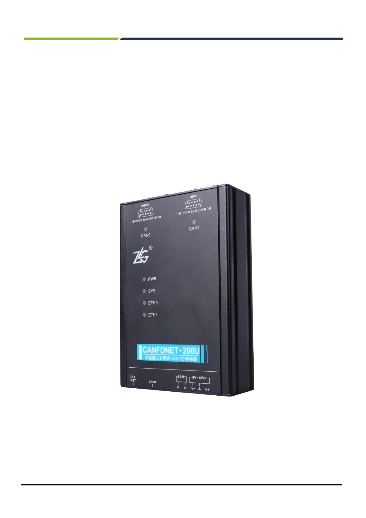
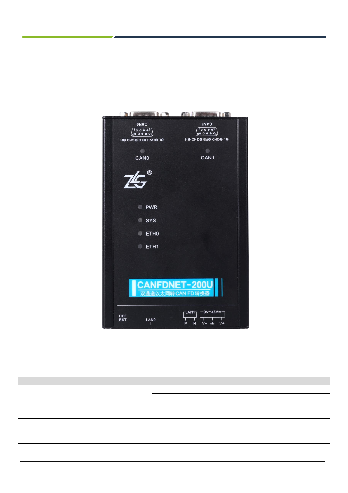
1.1 Product Overview.........................................................................................................................................1
1.2 Product Features..........................................................................................................................................2
1.2.1 Powerful Hardware............................................................................................................................2
1.2.2 Perfect Functions...............................................................................................................................2
2. Product Specifications .................................................................................................................3
2.1 Electrical Specifications ...............................................................................................................................3
2.2 Operating temperature.................................................................................................................................3
2.3 Protection Level............................................................................................................................................3
3. Dimensions..................................................................................................................................4
4. Hardware Interfaces.....................................................................................................................5
4.1 Panel Layout ................................................................................................................................................5
4.2 Indicators......................................................................................................................................................5
4.3 Buttons.........................................................................................................................................................6
4.4 Power Interface............................................................................................................................................6
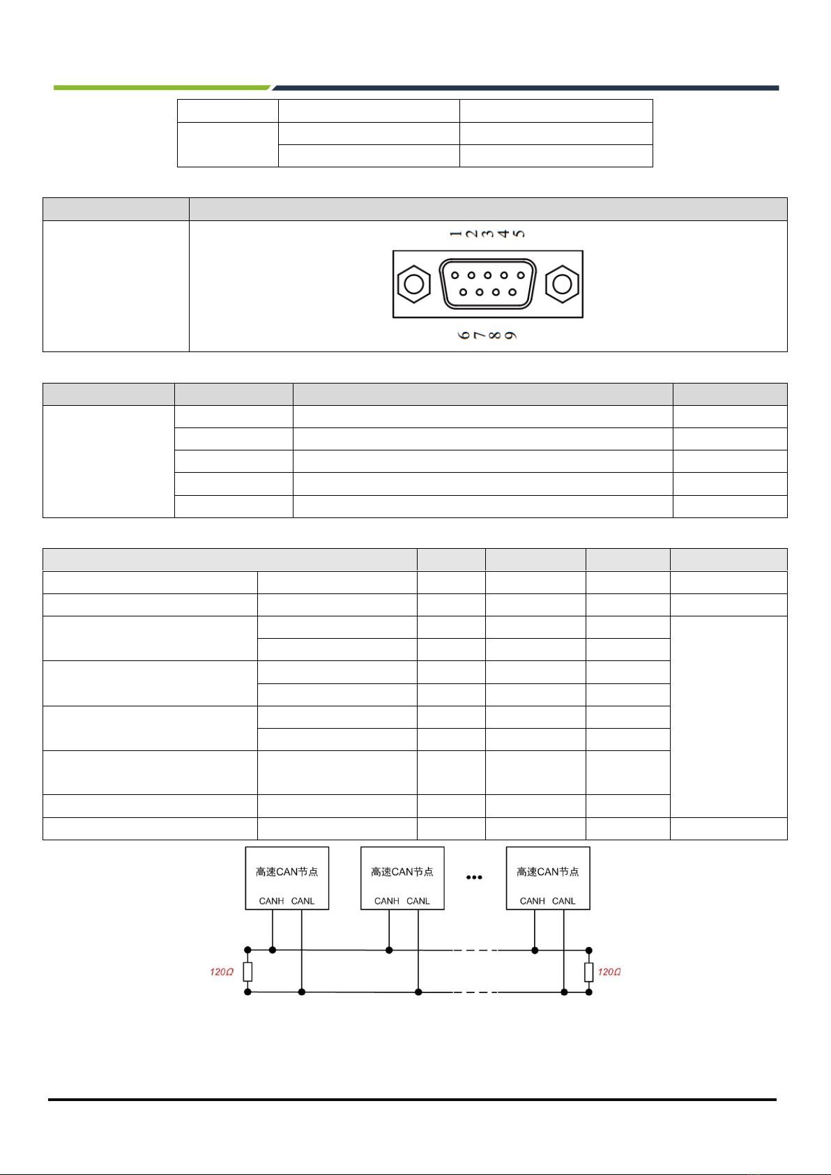
4.5 CAN-bus Interface........................................................................................................................................6
4.6 Ethernet Interface.........................................................................................................................................8
4.7 Vehicle Ethernet Interface............................................................................................................................9
5. Quick Instructions ......................................................................................................................10
5.1 Hardware Connection ................................................................................................................................10
5.2 Software Installation...................................................................................................................................10
5.3 Device Configuration..................................................................................................................................10
5.3.1 Running the Configuration Tool .......................................................................................................10
5.3.2 Searching Devices...........................................................................................................................11
5.3.3 Configuring Parameters...................................................................................................................12
5.4 Working Mode Instructions.........................................................................................................................14
5.4.1 TCP Server Mode............................................................................................................................14
5.4.2 TCP Client Mode..............................................................................................................................16
5.4.3 UDP Mode........................................................................................................................................17
6. Other Functions .........................................................................................................................19
6.1 Resetting the Device..................................................................................................................................19
6.2 Restoring Factory Settings.........................................................................................................................19
6.3 Upgrading the Device.................................................................................................................................19
7. Appendix....................................................................................................................................21
7.1 CANFDNET Network Data Format............................................................................................................21
7.2 Configuration Parameters..........................................................................................................................24
8. Disclaimer..................................................................................................................................29

CANFDNET-200U
High-Performance Dual-Channel Ethernet to CAN (FD) Converter User Manual
©2021 Guangzhou ZLG Electronics Co., Ltd.
1
User Manual
1. Product Introduction
1.1 Product Overview
CANFDNET-200U is a high-performance industrial Ethernet and CAN(FD)-bus data converter developed by
Guangzhou ZLG Electronics Co., Ltd. It integrates two CAN(FD)-bus interfaces, one Ethernet interface, and one
vehicle dual-wire Ethernet interface, and provides a stable TCP/IP protocol stack. It helps users easily
interconnect the CAN(FD)-bus network and Ethernet, and further expands the scope of CAN(FD)-bus network.
CANFDNET-200U is an industrial-grade product that supports an operating temperature of -40°C to +85°C. It
has one 10M/100M adaptive Ethernet interface, one 100M on-board dual-wire Ethernet interface, and two CAN
(FD) ports with a maximum baud rate of 5 Mbps. It has TCP Server, TCP Client, UDP and other work modes.
Users can flexibly set configuration parameters by using the configuration software.
Figure1.1 Product appearance

CANFDNET-200U
High-Performance Dual-Channel Ethernet to CAN (FD) Converter User Manual
©2021 Guangzhou ZLG Electronics Co., Ltd.
2
User Manual
1.2 Product Features
1.2.1 Powerful Hardware
⚫High-speed 600MHz main-frequency 32-bit processor;
⚫10M/100M self-applicable Ethernet interface, 2 kV electromagnetic isolation;
⚫Vehicle dual-wire Ethernet, meeting the OPEN Alliance BroadR-Reach specification
⚫Two CAN (FD) ports, 2.5 kVDC withstand voltage isolation;
⚫Embedded hardware watchdog;
⚫Rated power supply voltage range 9V-48V DC;
⚫Operating temperature: -40°C to +85°C;
⚫Humidity: 5%-95% RH, no condensation;
⚫Rugged metal housing, SECC metal (1.1 mm);
⚫Designed specifically for industrial environments.
1.2.2 Perfect Functions
⚫CAN(FD) interface functions supported:
◼Support baud rate 40K-5Mbps, baud rate can be set arbitrarily;
◼Support various controller types: CAN, CANFD ISO or CANFD Non-ISO;
◼Support the software terminal resistance switch;
◼Support message filtering;
◼Support millisecond-level message timing sending;
◼Support bus utilization reporting;
◼The message sending buffer can be set, and the user can choose the most suitable balance
between real-time and large-capacity buffering;
⚫Multiple work modes supported:
◼Work modes: TCP Server, TCP Client, UDP;
◼Supports a maximum of two TCP servers, each of each supports a maximum of 16 connections; or
supports a maximum of 16 TCP Client or UDP connections;
◼In each mode, you can choose to upload the CAN (FD) channel message and error message, which
can be flexibly used in various scenarios;
◼The TCP Server/Client mode connection has a built-in TCP keep-alive mechanism to ensure
reliable TCP connections;
◼In TCP Client mode, the network will automatically reconnect after disconnection, and the TCP
connection will be established reliably;
◼In UDP mode, support multicast, IP segment and other operations to support multiple users to
control multiple CAN (FD) channels at the same time;
◼Supported TCP/IP protocols include IP,ARP, ICMP, UDP, DHCP, DNS, TCP;
◼Flexible CAN (FD) packet settings meet various packet requirements of users;
◼The communication protocol is open, and the secondary development interface function library is
provided (Windows and Linux platforms supported);
⚫You can configure the working parameters by using the configuration tool, and provide the secondary
development interface function library (Windows, Linux platforms supported);
⚫Support TCP/UDP data conversion between vehicle Ethernet and Ethernet;
⚫Support local system firmware upgrade.

CANFDNET-200U
High-Performance Dual-Channel Ethernet to CAN (FD) Converter User Manual
©2021 Guangzhou ZLG Electronics Co., Ltd.
3
User Manual
2. Product Specifications
2.1 Electrical Specifications
Table 2.1 Electrical specifications
Item
Conditions
Rating
Unit
Minimum
Typical Value
Maximum
Working voltage
DC
9
12
48
V
Power consumption
-
1.5
-
W
2.2 Operating Temperature
Table 2.2 Operating temperature
Item
Rating
Unit
Minimum
Typical Value
Maximum
Operating temperature
-40
-
85
℃
Storage Temperature
-40
-
85
℃
2.3 Protection Level
Table 2.3 Protection level-electrostatic discharge immunity test (IEC61000-4-2)
Interface
Test Level
Test Voltage (kV)
Test Result
Remarks
Power supply
Level 4
6
Class A
Contact discharge
CAN bus
Level 4
6
Class A
Contact discharge
Ethernet
Level 4
6
Class A
Contact discharge
Buttons, Indicators
Level 4
8
Class A
Air discharge
Table 2.4 Protection level-electrical fast transient pulse group immunity test (IEC61000-4-4)
Interface
Test level
Test voltage (kV)
Test Result
Remarks
Power supply
Level 3
2
Class A
Capacitive coupling
CAN bus
Level 3
2
Class A
Capacitive coupling
Ethernet
Level 3
2
Class A
Capacitive coupling
Table 2.5 Protection level-surge (impact) test (IEC61000-4-5)
Interface
Test Level
Test Voltage (kV)
Test Result
Remarks
Power supply
Level 3
1
Class A
Line-line
Level 3
1
Class A
Line-ground
CAN bus
Level 3
1
Class A
Line-line
Level 3
1
Class A
Line-ground
Ethernet
Level 3
1
Class A
Line-line
Level 3
1
Class A
Line-ground

CANFDNET-200U
High-Performance Dual-Channel Ethernet to CAN (FD) Converter User Manual
©2021 Guangzhou ZLG Electronics Co., Ltd.
4
User Manual
3. Mechanical Dimensions
The mechanical dimensions are shown in the following figure (unit: mm)
Figure3.1 Host dimensions

CANFDNET-200U
High-Performance Dual-Channel Ethernet to CAN (FD) Converter User Manual
©2021 Guangzhou ZLG Electronics Co., Ltd.
5
User Manual
4. Hardware Interfaces
This section describes the hardware interfaces of CANFDNET-200U series equipment.
4.1 Panel Layout
Figure 4.1 shows the device panel layout.
Figure 4.1 Panel layout
4.2 Indicators
Table 4.1 LED indicators
Identification
Function
Status
Description
PWR
Power indicator
Red
The device is powered on properly
Light off
The device is not powered on
SYS
System indicator
Green flashing
System running
Red
Device reset and restart
CAN0/CAN1
CAN channel indicator
Green normally on
Channel open
Green flashing
The CAN channel normally sends and
receives data
Flash in red
CAN bus error

CANFDNET-200U
High-Performance Dual-Channel Ethernet to CAN (FD) Converter User Manual
©2021 Guangzhou ZLG Electronics Co., Ltd.
6
User Manual
ETH0
Ethernet indicator
Green normally on
Ethernet connected
Light off
Ethernet no connected
Green flashing
The application has data transmission and
reception
Flash in red
Received data parsing error
ETH1
Vehicle Ethernet Indicator
Green normally on
Ethernet connected
Light off
Ethernet no connected
Green flashing
The app has data transfer
LAN0
RJ45 interface indicator - yellow
indicator
The yellow indicator is on
Ethernet connection, no data transmission
and reception
The yellow indicator blinks
The Ethernet has data transmission and
reception
Light off
Ethernet no connected
RJ45 interface indicator - green
indicator
The green indicator is on
Ethernet speed 100Mbps
Light off
Ethernet speed 10Mbps
4.3 Buttons
The device provides the factory settings restoration (DEF)/system reset (Reset) button. After pressing the
button, release it within 2 seconds to reset the device; if you press and hold (5 seconds) the button until the
system indicator SYS turns red, the device restores its factory settings automatically.
4.4 Power Interface
The rated voltage of the power input of the equipment is DC 9-48 V, and the shell is marked as "DC 9-48V".
The physical form of the interface is 5.08 terminal. Table 4.2 and Table 4.3 show the interface diagram and signal
definition.
Table 4.2 Power interface
Type
Schematic Diagram
5.08 terminal
Table 4.3 5.08 terminal signal definition
Function Interface
Signal Definition
Signal Description
Interface Type
5.08 Interface
Power supply
V+
Positive electrode of power
√
V-
Negative electrode of power
√
EARTH
Ground
√
4.5 CAN-bus Interface
The device provides two isolated CAN-Bus interfaces. The shell identification is "CAN0" and "CAN1". The
physical form of the interface is DB9 terminal. Table 4.4, Table 4.5, Table 4.6, and Table 4.7 list the interface
diagram, signal definition, and interface specifications.
Table 4.4 CAN channel performance
Channel
Transmission Direction
Maximum Rate (unit: frame/s)
CAN0
Receive
6,000 frames/s

CANFDNET-200U
High-Performance Dual-Channel Ethernet to CAN (FD) Converter User Manual
©2021 Guangzhou ZLG Electronics Co., Ltd.
7
User Manual
Send
4,000 frames/s
CAN1
Receive
10,000 frames/s
Send
6,000 frames/s
Table 4.5 Pin definitions
Type
Schematic Diagram
Pin definitions
Table 4.6 Signal definition
Function Interface
Signal Definition
Signal Description
Pin Number
CAN0~CAN1
CAN_L
CAN data transceiving differential inverted signal
2
CAN_GND
CAN isolated ground
3, 6
CAN_H
CAN data sending and receiving differential positive phase signal
7
CAN_FG
Shielding ground
5
NC
Not connected
1, 4, 8, 9
Table 4.7 CAN-Bus interface specifications
Item
Minimum
Typical Value
Maximum
Unit
Communication baud rate
40K
5M
bps
Number of nodes
110
pcs
Dominant level (logic 0)
CANH
2.75
3.5
4.5
V
CANL
0.5
1.5
2
Recessive level (logic 1)
CANH
2
2.5
3
CANL
2
2.5
3
Differential level
Dominant (logic 0)
1.2
2
3.1
Recessive (logic 1)
-0.5
0
0.05
Maximum withstand voltage of the
bus pin
-18
18
Instantaneous voltage of the bus
-100
+100
Isolation voltage (DC)
3500
V
Figure 4.2 Typical high-speed CAN network connection
Balanced transmission is adopted for the CAN bus. According to ISO11898-2: In the high-speed CAN, a 120

CANFDNET-200U
High-Performance Dual-Channel Ethernet to CAN (FD) Converter User Manual
©2021 Guangzhou ZLG Electronics Co., Ltd.
8
User Manual
ohm terminal resistor needs to be connected to the network terminal node to eliminate signal reflection on the bus
and avoid signal distortion. Figure 4.2 shows the high-speed CAN network topology.
The device has a built-in 120 ohm terminal resistance, which can be configured to turn on or off by using the
CANFDNET configuration tool.
Note: The bus communication distance and communication rate are related to the field application and can
be designed according to the actual application and related standards. The CAN-Bus cable can be ordinary
twisted pair, shielded twisted pair or standard bus communication cable. In long-distance communication, the
terminal resistance value needs to be selected according to the communication distance, cable impedance and
number of nodes.
4.6 Ethernet Interface
The device provides one Ethernet interface. The physical form of the interface is RJ45, which realizes the
communication between the device and the PC. Table 4.8 lists the interface definition.
Table 4.8 Ethernet interface
Type
Schematic Diagram
RJ45 terminal

CANFDNET-200U
High-Performance Dual-Channel Ethernet to CAN (FD) Converter User Manual
©2021 Guangzhou ZLG Electronics Co., Ltd.
9
User Manual
4.7 Vehicle Ethernet Interface
The device provides one vehicle Ethernet interface, which meets the OPEN Alliance BroadR-Reach
specification. The physical form of the interface is an OPEN terminal, which realizes vehicle Ethernet
communication. This interface meets the 10/100M specification. Table 4.9, Table 4.10, and Figure 4.3 show the
interface diagram and signal definition.
Table 4.9 Vehicle Ethernet interface
Type
Schematic Diagram
5.08 terminal
Table 4.10 Signal definition
Function Interface
Signal Definition
Signal Description
Pin Number
LAN1
P
LAN1 data transceiver differential positive phase signal
1
N
LAN1 data transceiver differential inverted signal
2
Figure 4.3 Typical network connection of vehicle Ethernet

CANFDNET-200U
High-Performance Dual-Channel Ethernet to CAN (FD) Converter User Manual
©2021 Guangzhou ZLG Electronics Co., Ltd.
10
User Manual
5. Quick Guide
This chapter introduces the basic usage of CANFDNET-200U. You will quickly master its use and have an
intuitive understanding of data forwarding between Ethernet and CAN (FD).
CANFDNET-200U supports three work modes, which can work at the same time. This chapter introduces
each work mode.
5.1 Hardware Connection
Connect the device to a 9-48 V DC power supply, and use a crossover cable to connect the LAN port of the
device to the network port of the PC.
5.2 Software Installation
Before using the device, install the ZCANPRO (V2.0.39 or above), which can be downloaded from the official
website.
5.3 Device Configuration
Before using the device, configure the device IP address, CAN port baud rate and other parameters.
Configure the device by using the network device configuration tool in ZCANPRO. The procedure is as follows:
5.3.1 Running the Configuration Tool
Open the ZCANPRO software, click [Tools] in the upper part of the software, and select [Network Device
Configuration Tool], as shown in the red circle in Figure 5.1. Figure 5.2 shows the configuration software interface.
Figure 5.1 Running the network device configuration tool

CANFDNET-200U
High-Performance Dual-Channel Ethernet to CAN (FD) Converter User Manual
©2021 Guangzhou ZLG Electronics Co., Ltd.
11
User Manual
Figure 5.2 Network configuration tool interface
5.3.2 Searching Devices
Click the [Search Device] button in the upper left corner of Figure 5.2 to search for devices in the network.
After the device is searched, the interface is displayed as shown in Figure 5.3. Click the red circle in the figure and
select the device to obtain information.After obtaining the information, you can view the configuration information
on the right interface, as shown in Figure 5.4. For the description of each configuration item, see Configuration
parameter description in the appendix.
Figure 5.3 Interface displayed after successful search

CANFDNET-200U
High-Performance Dual-Channel Ethernet to CAN (FD) Converter User Manual
©2021 Guangzhou ZLG Electronics Co., Ltd.
12
User Manual
Figure 5.4 Device configuration display
5.3.3 Configuring Parameters
Whether the parameter configuration is correct or not will directly affect the normal communication. The
common parameter configurations are described below.
⚫Network parameters
Before using the PC to communicate with the device, ensure that an Ethernet card is installed on the user's
PC, and the PC and the device must be in the same network segment. The device is set with a default IP address
(192.168.0.178) and network mask (255.255.255.0) when it leaves the factory. Check whether the device is in the
same network segment as the user's PC according to the process shown in Figure 5.5 Same Network Segment
Detection Flowchart 5.5.
PC机子网掩码
?
PC机IP地址
?
PC机所属子网
?
设备IP地址
192.168.0.178
设备子网掩码
255.255.255.0
比较
设备所属子网
192.168.0.0
调整PC机IP地址 可以设置设备
与与
不相同 相同
Figure 5.5 Same network segment detection process
There are two methods to keep the user's PC and device in the same network segment.
The first method is to change the IP address of the PC. Open [Control Panel] on the PC, double-click the
[Network Connection] icon, click to select the [Local Area Connection] corresponding to the network card of the
connected device, right-click and choose [Properties]. Double-click on the pop-up page to select [Internet

CANFDNET-200U
High-Performance Dual-Channel Ethernet to CAN (FD) Converter User Manual
©2021 Guangzhou ZLG Electronics Co., Ltd.
13
User Manual
Protocol Version 4 (TCP/IPv4)]. The page as shown in Figure 5.6 appears. Select [Use the following IP address],
and enter the IP address 192.168.0.55, the subnet mask 255.255.255.0, and the default gateway 192.168.0.1
(the DNS part can be left blank). Click [OK] on this page and on the "LocalArea Connection Properties" page, and
wait until the system configuration is complete.
Figure 5.6 TCP/IP properties
The second method is to change the IP address of the device. On the interface in Figure 5.4, change the [IP]
item in [General Ethernet] to the IP address of the same network segment as the PC. For example, if the IP
address of the PC is 192.168.7.115, the subnet mask is 255.255.255.0, and the default gateway is 192.168.0.1,
change [IP] of [General Ethernet] to 192.168.7.178, and change the device gateway IP to "192.168.7.1".
⚫CAN(FD) parameters
For CAN(FD) normal communication, set the CAN(FD) baud rate to be consistent with that on the CAN-Bus
network. The device is configured as an ISO CANFD controller by default. The baud rate of the arbitration domain
is 1 Mbps, and the baud rate of the data domain is 5 Mbps. To modify the data, adjust the arbitration domain baud
rate and data domain baud rate in the CAN0/1 configuration on the interface.
⚫Work mode configuration
The factory work mode of the device is TCP Server mode, the port is 8000, and the network card is universal
Ethernet. Click the attribute value of [CAN(FD) to Ethernet] on the interface. On the pop-up interface, view or
modify the work mode, as shown in Figure 5.7.

CANFDNET-200U
High-Performance Dual-Channel Ethernet to CAN (FD) Converter User Manual
©2021 Guangzhou ZLG Electronics Co., Ltd.
14
User Manual
Figure 5.7 Data forwarding (work mode selection) interface
Select [View advanced configuration items] to view more configuration items.
After all configuration changes are completed, enter "88888" in the attribute value of [Current Password] in
[Password Operation], and click [Submit Changes].
5.4 Working Mode Instructions
When the device configuration is completed, the device works in the specific mode. The following describes
how to use each work mode based on ZCANPRO software.
5.4.1 TCP Server Mode
In TCP Server mode, the device will not actively connect with other devices. It always waits for the
connection of the client (TCP Client), and can carry out two-way data communication after establishing a TCP
connection with the client.
When the device acts as a TCP server, the PC should act as a TCP client. Open the [Device Management]
interface of ZCANPRO, select CANFDNET-TCP as the device type, and start the device.
On the device startup interface (as shown in Figure 5.8), select [Work Mode] as [Client], and enter [IP
address] and [working port]. If the current device IP address is "192.168.0.178" and the port is 8000, enter this
parameter.
[Protocol] is determined by the [controller type] of CAN configuration. If it is configured as a CAN controller,
select CAN; if it is configured as ISO/Non-ISO CANFD, select CANFD.

CANFDNET-200U
High-Performance Dual-Channel Ethernet to CAN (FD) Converter User Manual
©2021 Guangzhou ZLG Electronics Co., Ltd.
15
User Manual
[CANFD acceleration] is determined by the user. When [No] is selected, all CANFD messages sent are not
accelerated; otherwise, they are all accelerated.
Click [OK]. ZCANPRO will connect to the device.
Figure 5.8 Starting the CANFDNET-TCP client
After starting the device, you can use ZCANPRO to communicate with the device. To verify whether the
device communication is normal, connect CAN0 and CAN1 of the device (the baud rate must be the same) to
carry out the message sending and receiving test.
Click the [Send Data] icon on the ZCANPRO interface and select [Normal Send]. On the displayed sending
interface, select [Channel] to specify the sending channel, and click [Send Now] to send the message.
As CAN0 is connected to CAN1, the message sent by CAN0 will be received by CAN1. You can see two
messages on the main interface. One is the sending message and the other is the receiving message, from
CAN0 and CAN1 respectively, as shown in Figure 5.9.

CANFDNET-200U
High-Performance Dual-Channel Ethernet to CAN (FD) Converter User Manual
©2021 Guangzhou ZLG Electronics Co., Ltd.
16
User Manual
Figure 5.9 Message sending interface
So far, the basic use of CANFDNET equipment has been realized.
5.4.2 TCP Client Mode
In TCP Client mode, the device will actively connect to the preset TCP server. If the connection is
unsuccessful, the client will continue to try to establish a connection with the TCP server based on the preset
connection conditions. After establishing a TCP connection with the TCP server, two-way data communication
can be carried out.
When the device acts as a TCP Client, the PC should act as a TCP server. Open the [Device Management]
interface of ZCANPRO, select CANFDNET-TCP as the device type, and start the device.
On the pop-up startup device interface (as shown in Figure 5.10), set [Work Mode] to [Server], and enter
[Local Port]. For example, the current device IP address is "192.168.0.178", the target IP address of the client
connection is "192.168.0.55", and the target port is 8000. On the ZCANPRO startup interface, set [local port] to
8000, and change the IP address of the PC to "192.168.0.55".

CANFDNET-200U
High-Performance Dual-Channel Ethernet to CAN (FD) Converter User Manual
©2021 Guangzhou ZLG Electronics Co., Ltd.
17
User Manual
Figure 5.10 Starting the CANFDNET-TCP server
Click [OK]. The device connects to ZCANPRO. The communication with the device is set up. For
communication information, see TCP Server mode.
5.4.3 UDP Mode
In UDP mode, the UDP protocol is used for data communication. UDP is a non-connection-based
communication method. It cannot guarantee that the data packets sent to the target host will be received correctly.
Therefore, in the scenarios with high reliability requirements, the upper-layer communication protocol must be
used to ensure that the data is correct; however, because UDP is a simple communication method, it will not
increase too much additional communication volume, and can provide a higher communication speed than the
TCP method to ensure the real-time transmission of data packets. In fact, when the network environment is
simple and the network communication load is not too large, the UDP working method is not error prone. The
devices working in this mode are equal, and there is no server and client.
When the device is in UDP mode, the PC should also work in UDP mode. On the [Device Management]
interface of ZCANPRO, set the device type to [CANFDNET-UDP], and start the device.
On the displayed startup device interface (as shown in Figure 5.11), set [local port], [IP address], and
[working port]. For example, if the current device IP address is "192.168.0.178", the connection target IP address
is "192.168.0.55", the target port is 8000, and the local port is 4001, set [Local Port] to the device target port 8000,
[IPAddress] to the device IP address "192.168.0.178", and [Working Port] to the device local port 4001.
Table of contents
Other ZLG Media Converter manuals