ZLG CANFDNET-400U Operational manual

Product User Manual
CANFDCOM-100IE
RS232/485/422-CAN(FD)-BUS Intelligent Protocol converter
User Manual
UM01010101 V1.02 Date: 2019/08/20
Category
Contents
Keywords
RS232, CAN, conversion, baud rate
Description
This converter quickly connects RS232/485/422
communication equipment to the CAN(FD)-BUS field bus
©2021 Guangzhou ZLG Microelectronics Technology Corp.,Ltd.

CANFDNET-400U
High-performance Four-channel CANFD Bus-to-Ethernet Converter User Manual
©2021 Guangzhou ZLG Microelectronics Technology Corp.,Ltd.
i
User Manual
Revision History
Version
Date
Reason
V1.00
April 11,
2018
Created
V1.01
March 15,
2019
Updated the document header and footer and "Sales and Service
Network" content and added the "Disclaimer" content
V1.02
August 19,
2019
Added the product mechanical dimensions

CANFDNET-400U
High-performance Four-channel CANFD Bus-to-Ethernet Converter User Manual
©2021 Guangzhou ZLG Microelectronics Technology Corp.,Ltd.
1
User Manual
Contents
1. Functions .....................................................................................................1
1.1 Overview.................................................................................................................1
1.2 Features..................................................................................................................1
1.3 Typical Applications................................................................................................1
2. Hardware .....................................................................................................3
2.1 Appearance ............................................................................................................3
2.2 Interfaces................................................................................................................3
2.3 Indicators................................................................................................................4
2.4 Buttons....................................................................................................................5
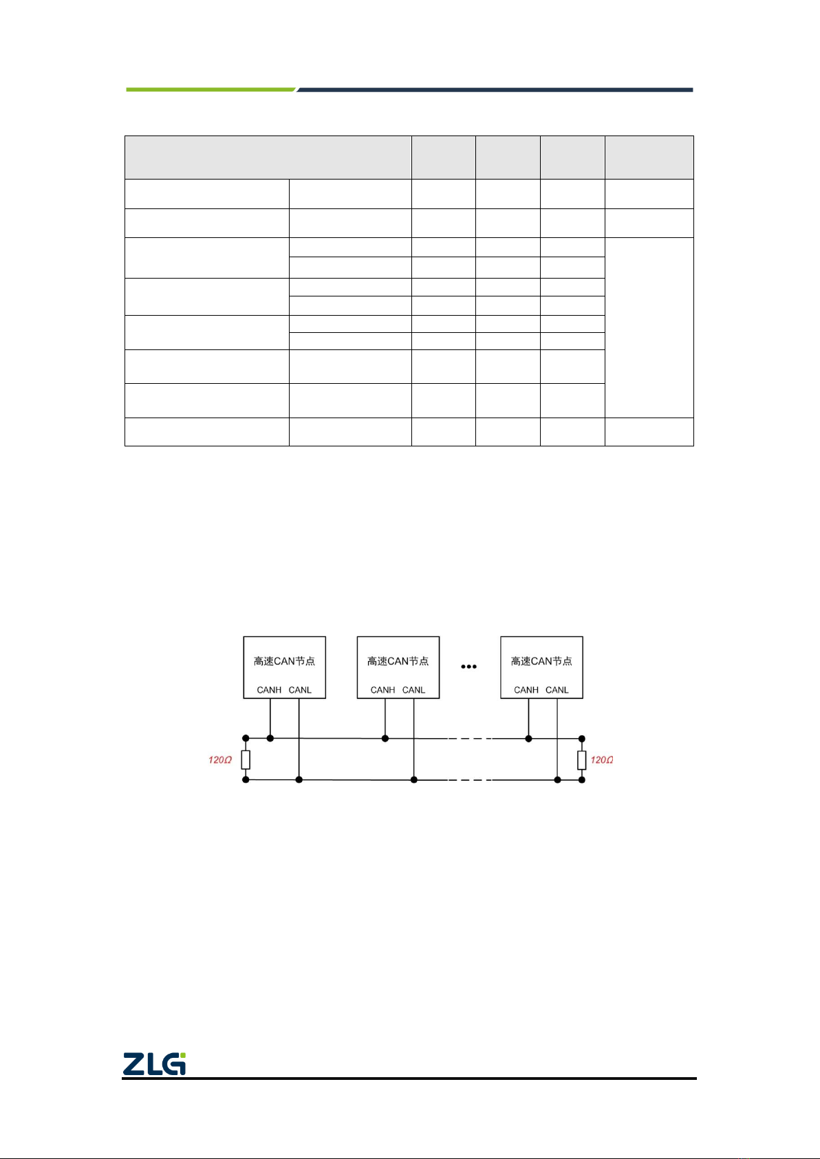
2.5 CAN Bus Connection .............................................................................................5
2.6 Mechanical Dimensions .........................................................................................6
3. Configuration Tool Installation and Description............................................8
3.1 Entering Configuration Mode..................................................................................8
3.2 PC Software Configuration.....................................................................................8
3.2.1 Conversion Parameters...............................................................................9
3.2.2 Serial Port Parameters...............................................................................11
3.2.3 CAN Parameters........................................................................................11
3.2.4 Filter Parameters........................................................................................14
3.2.5 Button Description......................................................................................14
4. Conversion Modes.....................................................................................16
4.1 Transparent Conversion.......................................................................................17
4.1.1 Frame Formats...........................................................................................17
4.1.2 Conversion Methods..................................................................................17
4.1.3 Conversion Examples................................................................................20
4.2 Transparent Conversion with Flags......................................................................23
4.2.1 Frame Formats...........................................................................................23
4.2.2 Conversion Methods..................................................................................24
4.2.3 Conversion Examples................................................................................27
4.3 Format Conversion...............................................................................................30
4.4 Modbus Conversion..............................................................................................32
4.4.1 Frame Formats...........................................................................................32
4.4.2 Conversion Methods..................................................................................34
4.4.3 Conversion Examples................................................................................36
5. Quick Instructions ......................................................................................38
5.1 Configuring the Converter....................................................................................38
5.1.1 Entering Configuration Mode.....................................................................38
5.1.2 Connecting the Converter by Using the Configuration Tool ......................38
5.1.3 Setting the Save Parameters.....................................................................39
5.2 Communication Test.............................................................................................39
6. Firmware Upgrade.....................................................................................41
7. Disclaimer..................................................................................................43

CANFDNET-400U
High-performance Four-channel CANFD Bus-to-Ethernet Converter User Manual
©2021 Guangzhou ZLG Microelectronics Technology Corp.,Ltd.
1
User Manual
1. Functions
1.1 Overview
CANFDCOM-100IE intelligent protocol converter quickly connects RS-232/485/422
communication equipment to the CAN(FD)-BUS field bus.
The converter supports 1200-921600bps serial port baud rate, 50k-5Mbps CAN
(FD)-bus communication rate.
The converter supports four conversion modes: transparent conversion, transparent
conversion with flags, format conversion, and Modbus conversion.
The CANFDCOM-100IE converter provides configuration software, which can flexibly
set the operating parameters of the CANFDCOM-100IE.
1.2 Features
Realize bidirectional data communication between CAN (FD)-bus and
RS-232/485/422;
Support CAN2.0A and CAN2.0B protocols, and comply with ISO-119898
specification;
Integrate one CAN-bus communication interface, and support user-defined
communication baud rate;
CANFDCOM-100IE integrates one 3-wire RS-232 communication interface, one
2-wire RS-485 communication interface, and one 4-wire RS-422 communication
interface. The communication rate can be set between 1,200-921,600 bps;
Provides four data conversion modes: transparent conversion, transparent
conversion with flags, format conversion, and Modbus conversion;
The CAN-bus circuit adopts 2,500 V DC electrical isolation;
Can be used in environments with safety and explosion-proof requirements;
Operating temperature: -40℃to +85℃;
Operating power: less than 2 W;
1.3 Typical Applications
Coal mine telecommunication;
PLC equipment networking;
The existing RS-232/485/422 equipment is connected to the CAN (FD)-bus network;
Extended standard RS-232/485/422 network communication length;
The PLC equipment is connected to the CAN(FD)-bus network;
Gateway bridge between CAN(FD)-bus and serial bus;
Industrial field network data monitoring;
CAN (FD) teaching application remote communication;
CAN (FD) industrial automation control system;

CANFDNET-400U
High-performance Four-channel CANFD Bus-to-Ethernet Converter User Manual
©2021 Guangzhou ZLG Microelectronics Technology Corp.,Ltd.
2
User Manual
Low-speed CAN (FD) network data acquisition data analysis;
CAN(FD)-bus application system such as the intelligent building control data
broadcasting system;

CANFDNET-400U
High-performance Four-channel CANFD Bus-to-Ethernet Converter User Manual
©2021 Guangzhou ZLG Microelectronics Technology Corp.,Ltd.
3
User Manual
2. Hardware
2.1 Appearance
Figure 2.1 shows the appearance.
Figure 2.1 CANFDCOM-100IE appearance
2.2 Interfaces
The CANFDCOM-100IE converter has three user interfaces: one CAN (FD)-bus
interface, one 485/422 interface, one RS-232 interface. Table 2.1 lists the interface pin

CANFDNET-400U
High-performance Four-channel CANFD Bus-to-Ethernet Converter User Manual
©2021 Guangzhou ZLG Microelectronics Technology Corp.,Ltd.
4
User Manual
definitions.
Table 2.1 Interface description
Type
Schematic Diagram
Pin definitions
Pin description
DB9 socket
1: NC
Dangling
2: CAN_L
CAN data transceiving
differential inverted signal
3, 6: CAN_GND
CAN isolated ground
4, 8: NC
Dangling
5: Shield
Shielding ground
7: CAN_H
CAN data sending and
receiving differential
positive phase signal
9: NC
Dangling
RS232
terminal
(female)
2:TXD
RS232 send
3:RXD
RS232 receive
5:RS232_GND
RS232 isolated ground
1, 4, 6, 7, 8, 9:NC
Dangling
OPEN8
terminal
1234 5 67 8
1:485A_R+
485A/422 receive positive
phase signal
2:485B_R-
485B/422 receive inverted
signal
3:485\422_GND
485\422 isolated ground
4:422_T+
422 send a positive phase
signal
5:422_T-
422 send inverted signal
6:GND
Power input negative
7:EARTH
Ground
8:9V-48V
Power input positive
2.3 Indicators
There are four LEDs on the converter to indicate the operating status of the
CANFDCOM-100IE converter. Table 2.2 lists the functions.
Table 2.2 LED indicators
Identification
Function
Status
Description
PWR
Converter power
indicator
The indicator
is on
The converter power supply is working
properly
The indicator
The converter power supply is not powered

CANFDNET-400U
High-performance Four-channel CANFD Bus-to-Ethernet Converter User Manual
©2021 Guangzhou ZLG Microelectronics Technology Corp.,Ltd.
5
User Manual
is off
CAN
CAN communication
status indicator
Flashing red
light
There is an error in CAN communication,
and an error frame is received
Green
flashing light
The CAN side is transmitting data properly
COM
RS-232/485/422
communication
status indication
Flashing red
light
Baud rate mismatch error occurs in serial
communication
Green
flashing light
The serial port side is transmitting data
properly
CFG
Configuration status
indicators
The indicator
is off
In conversion working mode, normal data
forwarding
Normally on
In configuration mode. You can configure
parameters and perform other operations
Flash
In BootLoader, firmware upgrade in
progress
2.4 Buttons
Table 2.3 Button operations
Operation
Function
ON
Make the converter in normal working state and perform normal data forwarding
CFG
Put the converter in the configured state. Normal data conversion is impossible in the
configured state. Only in the configuration state can the host computer or AT commands be
used for parameter configuration
2.5 CAN Bus Connection
The physical layer mainly transmits inter-device signals, converts various information
into transmittable physical signals (usually electrical or optical signals), and transmits
these signals to other target devices. For this purpose, CAN-bus has made detailed
regulations on signal levels, cables and connectors used for communication.
Two standards are released after CAN-bus was standardized by ISO, namely
ISO11898-2 (125kbps-1Mbps high-speed communication standard) and ISO11898-3
(low-speed communication standard less than 125 kbps).
The data link layer is the same for both high-speed CAN and fault-tolerant CAN
except for the physical layer. The CAN transceiver determines the bus level based on the
voltage difference between the two cables. This transmission method is called differential
transmission. There are only two possibilities for the level signal transmitted on the cable,
namely the dominant level and the recessive level. The dominant level indicates logic 0,
and the recessive level indicates logic 1. Table 2.4 lists the high-speed CAN electrical
characteristics.

CANFDNET-400U
High-performance Four-channel CANFD Bus-to-Ethernet Converter User Manual
©2021 Guangzhou ZLG Microelectronics Technology Corp.,Ltd.
6
User Manual
Table 2.4 CAN-BUS interface specifications
parameter
Minimu
m
Typical
value
Maximu
m
Unit
Communication baud rate
5k
5M
bps
Number of nodes
110
pcs
Dominant level (logic 0)
CANH
2.75
3.5
4.5
V
CANL
0.5
1.5
2
Recessive level (logic 1)
CANH
2
2.5
3
CANL
2
2.5
3
Differential level
Dominant (logic 0)
1.2
2
3.1
Recessive (logic 1)
-0.5
0
0.05
Maximum withstand
voltage of the bus pin
-18
18
Instantaneous voltage of
the bus
-100
+100
Isolation voltage (DC)
2500
V
The CAN bus adopts balanced transmission. ISO11898-2 stipulates: In the
high-speed CAN, a 120 ohm terminal resistor needs to be connected to the network
terminal node to eliminate signal reflection on the bus and avoid signal distortion. Figure
2.2 shows the high-speed CAN network topology.
The device has a built-in 120-ohm terminal resistance, which can be configured to be
turned on or off by using the CANFDCOM configuration tool. For operation details, see
3.2.3.
Figure 2.2 High-speed CAN network topology
Note: The bus communication distance and communication rate are related to the field application and
can be designed according to the actual application and related standards. The CAN-Bus cable can use
ordinary twisted pair, shielded twisted pair or standard bus communication cable. In long-distance
communication, the terminal resistance value needs to be selected according to the communication
distance, cable impedance and number of nodes.
2.6 Mechanical Dimensions
Figure 2.3 shows the mechanical dimensions (unit: mm).

CANFDNET-400U
High-performance Four-channel CANFD Bus-to-Ethernet Converter User Manual
©2021 Guangzhou ZLG Microelectronics Technology Corp.,Ltd.
7
User Manual
Figure 2.3 Mechanical dimensions

CANFDNET-400U
High-performance Four-channel CANFD Bus-to-Ethernet Converter User Manual
©2021 Guangzhou ZLG Microelectronics Technology Corp.,Ltd.
8
User Manual
3. Configuration Tool Installation and Description
The operating parameters of CANFDCOM-100IE support two configuration methods.
The first is to use the host computer software, and the second is to useAT commands. For
how to use AT command for configuration, see the CANFDCOM Series AT Command
Instructions. Both configuration methods require the repeater to enter configuration mode.
3.1 Entering Configuration Mode
To put the converter into configuration mode, a dedicated configuration switch is set,
as shown in Figure 3.1. Set the switch to the "CFG" position. The system is in the
configuration state, and the CFG indicator is on. The converter can be configured. After
configuring the device, set the "configuration switch" to "ON"! In normal operation.
Figure 3.1 Configuration switch
3.2 PC Software Configuration
The configuration software name of the CANFDCOM-100IE converter is
"CANCOM-100IE configuration". The setting software is included on the CD-ROM
delivered with the product. Figure 3.2 shows the software interface.

CANFDNET-400U
High-performance Four-channel CANFD Bus-to-Ethernet Converter User Manual
©2021 Guangzhou ZLG Microelectronics Technology Corp.,Ltd.
9
User Manual
Figure 3.2 Configuration software interface
After the converter enters the configuration mode, the parameters can be set by using
the software; otherwise, the software will consider the converter not connected. After
setting the configuration parameters, click Write Configuration to write the parameters to
the device for curing. The following describes the main configuration parameters in detail
with reference to the configuration software.
3.2.1 Conversion Parameters
Conversion parameters refer to parameters such as the conversion rule direction of
the converter. Figure 3.2 shows the conversion parameter interface.
Conversion mode: includes four selectable conversion modes: transparent
conversion, transparent conversion with flags, format conversion, and Modbus mode.
Conversion direction:
Bidirectional: The converter converts the data of the serial bus to the CAN bus, and
also converts the data of the CAN bus to the serial bus.
Only serial port to CAN: Only convert the data of the serial bus to the CAN bus,
without converting the data of the CAN bus to the serial bus.
Only CAN to serial port: Only convert the data of the CAN bus to the serial bus,
without converting the data of the serial bus to the CAN bus.
[Note]: By selecting the conversion direction, the data interference on the bus side
that does not need conversion can be eliminated.
Allow CAN frame information to be forwarded into serial frames:
This parameter is only used in "transparent conversion" mode. When this parameter
is selected, the converter will add the frame information of the CAN (CANFD) message to
the first byte of the serial frame when it is working. When this parameter is not selected,

CANFDNET-400U
High-performance Four-channel CANFD Bus-to-Ethernet Converter User Manual
©2021 Guangzhou ZLG Microelectronics Technology Corp.,Ltd.
10
User Manual
the frame information of CAN (CANFD) will not be converted.
Allow CAN frame flags to be forwarded into serial frames:
This parameter is only used in "transparent conversion" mode.When this option is
selected, the converter will add the frame ID of the CAN (CANFD) message before the
frame data of the serial frame and after the frame information (if frame information
conversion is allowed). When this parameter is not selected, the frame ID of CAN (CANFD)
is not converted.
Position of the CAN frame identifier in the serial frame:
This parameter is only used in transparent conversion with flags. When the serial port
data is converted into CAN (CANFD) messages, the offset address of the start byte of the
frame ID of the CAN (CANFD) message in the serial frame and the length of the frame ID
(see 4.2 Transparent Conversion with Flags).
[Note]: The frame ID length can be filled with 1 to 2 bytes in the standard frame,
corresponding to ID1 and ID0 of the CAN (CANFD) message respectively. When
extending the frame, 1 to 4 bytes of ID3, ID2, ID1 and ID0 can be filled.
The ID of the standard frame is 11 bits, and the ID of the extended frame is 29 bits.
Time interval (ms) between serial frames:
This parameter is used only in transparent conversion and transparent conversion
with flags. This parameter is the minimum time interval between two serial frames when
the user sends serial frames to the converter. The interval is in "milliseconds". The value is
0-500 ms.
[Note]: This time cannot be less than the time to transmit a single character;
otherwise, the repeater will be automatically set to an appropriate value (two characters of
time). The frame interval time sent by the user is preferably greater than the set time;
otherwise, the frame conversion may be incomplete.
The meaning of "time to transmit a single character" is: at the corresponding baud
rate, the time required for the serial port to transmit one character (10 bits); that is, divide
10 by the corresponding baud rate.
For example: at a baud rate of 9,600 bps, the "number of characters in the serial
frame interval" is 4, and the "time to transmit a single character (10 bits per character)" is
(10/9600)s, the obtained actual time interval between serial frames is:
(10/9600)*4=4.17(ms); that is, the time interval between two serial frames is at least 4.17
ms.
CAN frame forwarding interval (ms):
This parameter is valid in all modes. This parameter is the delay time between
forwarding CAN (CANFD) messages from the repeater.If this parameter is greater than 0,

CANFDNET-400U
High-performance Four-channel CANFD Bus-to-Ethernet Converter User Manual
©2021 Guangzhou ZLG Microelectronics Technology Corp.,Ltd.
11
User Manual
the repeater will buffer the data received by the serial port, and forward the data by
message at a time based on the preset delay time. The value is 0-500 ms. Note: The
repeater cache is limited. If the preset delay time is too long, it may cause too much data
accumulation at the serial port, which results in overflow and loss.
3.2.2 Serial Port Parameters
As shown in Figure 3.3, this option mainly sets serial port related parameters.
Figure 3.3 Serial port parameter settings
Baud rate: The baud rate of the serial port ranges between 1,200 bps and 921,600
bps.
The data is: between 7 and 8 bits.
Stop bit: 1 or 2.
Parity: no parity, even parity, or odd parity.
Mode switching: RS232 mode, RS485 mode, or RS422 mode.
3.2.3 CAN Parameters
As shown in Figure 3.4, this option mainly sets CAN related parameters.

CANFDNET-400U
High-performance Four-channel CANFD Bus-to-Ethernet Converter User Manual
©2021 Guangzhou ZLG Microelectronics Technology Corp.,Ltd.
12
User Manual
Figure 3.4 CAN parameter setting
CANFD standard: supports ISO standard and Bosch standard
Protocol: This parameter affects the transmission on the CAN side. CAN or CANFD
can be selected. When CAN is selected, the repeater forwards the serial port data into
CAN messages; when CANFD is selected, the repeater forwards the data as CANFD
messages.
Frame Type: frame type of the CAN (CANFD) message at the time of conversion. The
options include standard frames and extended frames.
CANFD acceleration: This parameter enables the baud rate switching function of
CANFD.
CAN ID: In "transparent conversion" mode, the forwarded CAN (CANFD) message
uses this ID. In other modes, the serial port data has an ID parameter, so this parameter is
invalid.
Terminal resistance enable: This parameter enables the built-in CAN bus 120-ohm
terminal resistance of the device.
Baud rate: includes the arbitration domain baud rate and data domain baud rate. In
CAN mode, the baud rate is determined by the arbitration domain baud rate, while the
data domain baud rate is invalid. In CANFD mode, if CANFD acceleration is enabled, the
data domain baud rate is valid. CAN bus baud rate. In addition to the standard baud rate
recommended by CIA in the list (sampling point 75-83.5%, SJW = 2, 3), a "custom baud
rate" option is also given. After selecting a custom baud rate, use the baud rate calculator
to calculate the desired baud rate value and fill it in the custom baud rate box as needed.
The baud rate calculator method is as follows:
1. As shown in Figure 3.5, set the arbitration domain baud rate in ①, and select the
appropriate synchronization jump width. The clock is fixed at 60 MHz;
2. Set the baud rate parameter of the data domain in ②, and select the appropriate

CANFDNET-400U
High-performance Four-channel CANFD Bus-to-Ethernet Converter User Manual
©2021 Guangzhou ZLG Microelectronics Technology Corp.,Ltd.
13
User Manual
synchronization jump width. The clock is fixed at 60 MHz;
3. After setting, click the calculation button at ③to list the calculation results of the
corresponding baud rate parameters;
4. Select the arbitration domain baud rate for the appropriate sampling point. If the
value is selected, the blue background color appears, indicating that the value is
selected, as shown in ④;
5. Select the data domain baud rate for the appropriate sampling point. If the value
is selected, the blue background color appears, indicating that the value is
selected, as shown in ⑤;
6. Click the copy button at ⑥to copy the value of the custom baud rate. Paste this
value into the custom baud rate text box.
Figure 3.5 Steps for using the baud rate calculator

CANFDNET-400U
High-performance Four-channel CANFD Bus-to-Ethernet Converter User Manual
©2021 Guangzhou ZLG Microelectronics Technology Corp.,Ltd.
14
User Manual
3.2.4 Filter Parameters
Figure 3.6 Baud parameter settings
CANFDCOM-100IE has the capability of hardware acceptance filtering and selective
reception, which minimizes the network load from the network. When setting the
acceptance filter, switch to the Filter Settings tab, as shown in Figure 3.6. Select the
"Enable Filter" option to enable the acceptance filter function. The filtering mode of
CANFDCOM-100IE is whitelist filtering. After filtering is enabled, only CAN (CANFD)
messages within the ID range of each filtering item in the filtering table are received. Note:
If filtering is enabled, but there is no filtering item in the filtering table, all packets will be
filtered at this time. The maximum number of filter items can be set to 64.
Example: As shown in Figure 3.6, the acceptance criteria frame IDs are set to 0x08
and 0x12. Extended frame group IDs are 0x55 to 0x66, and standard frame group IDs are
0x22 to 0x66. The repeater only receives standard frame CAN (CANFD) messages with
IDs 0x08, 0x12, 0x22-0x66 and extended frame CAN (CANFD) messages with IDs
0x55-0x66.
3.2.5 Button Description
Export configuration: Export its parameters to a parameter file, and save it.
Import configuration: Import the parameter file, and use the parameters in the
parameter file.
Restore default: Restore its parameters to their default values.
Firmware upgrade: Provides the function of upgrading the CANFDCOM-100IE
firmware.
Get configuration: Read out the parameters of the converter and display them on the
host computer software.

CANFDNET-400U
High-performance Four-channel CANFD Bus-to-Ethernet Converter User Manual
©2021 Guangzhou ZLG Microelectronics Technology Corp.,Ltd.
15
User Manual
Save configuration: After the parameters are set, click this button to write the
configuration parameters into the converter.

CANFDNET-400U
High-performance Four-channel CANFD Bus-to-Ethernet Converter User Manual
©2021 Guangzhou ZLG Microelectronics Technology Corp.,Ltd.
16
User Manual
4. Conversion Modes
CANFDCOM-100IE converter is an intelligent protocol converter that supports
conversion between serial port and CAN and conversion between serial port and CANFD.
Before use, you need to set the CAN type to be converted to the normal CAN or CANFD.
The converter provides four conversion modes, including transparent conversion,
transparent conversion with flags, format conversion, and Modbus conversion. The
parameters can be selected and set during converter configuration. Note: In the same
conversion mode, the CAN type is different, and the conversion method will change. For
example, in "transparent conversion", for ordinary CAN, the serial port receives a
maximum of eight bytes and must be converted into a CAN message. For CANFD, a
maximum of 64 bytes of data can be received and converted into CANFD messages.
"Transparent conversion" means that the converter just converts the bus data of one
format to the data bus of another format without appending or modifying the data. This
realizes the exchange of data format without changing the data content. The converter is
transparent to the bus at both ends. This method will not increase the user's
communication burden, but can convert the data as it is in real time, and can undertake
the transmission of data with a large flow.
"Transparent conversion with flags" is a special transparent conversion, with no
protocol attached. This conversion method is based on the common characteristics of
common serial frames and CAN (CANFD) messages, so that the two bus types can easily
form the same communication network. This method can convert the "address" in the
serial frame into the identification field of the CAN (CANFD) message. The starting
position and length of the serial frame "address" in the serial frame can be configured.
Therefore, in this way, the converter can adapt to the user's custom protocol to the
greatest extent.
"Format conversion" is one of the simplest usage patterns. The data is in a fixed
length. The fixed length of CAN is 13 bytes, and the fixed length of CANFD is 69 bytes.
That is, when the CAN type is set to ordinary CAN, the fixed serial frame data of 13 bytes
corresponds to a CAN message. When it is CANFD, the fixed 69-byte serial frame data
corresponds to one CANFD message. The fixed serial port frame content includes frame
information (1 byte) + ID (4 bytes) + data (8 bytes for CAN, 64 bytes for CANFD). By
correctly configuring the frame information (the data of the first byte), when the CAN type
is ordinary CAN, standard frames, extended frames and even remote frames of CAN can
be flexibly sent. When it is CANFD, it can send CANFD standard frame and extended
frame. Details of standard frames, extended frames and even remote frames can be
obtained by correctly parsing fixed-byte serial frames.
"Modbus conversion" refers to the conversion between the UART data of the
Modbus protocol and the CAN data. The Modbus protocol is a standard application layer
protocol, which is widely used in various industrial control scenarios. The protocol is open,
real-time, and has a good communication verification mechanism. It is ideal for scenarios
with high communication reliability requirements. The converter uses the standard

CANFDNET-400U
High-performance Four-channel CANFD Bus-to-Ethernet Converter User Manual
©2021 Guangzhou ZLG Microelectronics Technology Corp.,Ltd.
17
User Manual
Modbus RTU protocol format on the serial port side. Therefore, the converter not only
allows users to use the Modbus RTU protocol, but the converter can also directly interface
with other devices that support the Modbus RTU protocol. On the CAN or CANFD side, an
easy-to-use segmented communication format is developed to realize Modbus
communication. The role of the converter is still protocol verification and forwarding. It
supports Modbus protocol transmission, not Modbus master or slave host. The user can
communicate according to the Modbus protocol.
In "transparent conversion" and "format conversion", a byte of frame information is
used to identify some information of the CAN frame, such as type, format, and length.
Table 4.1 lists the frame information format.
Table 4.1 Frame format
FF
RTR
EDL
BRS (CANFD valid)
L3
L2
L1
L0
0: Standard
frame
1: Extended
frame
0: Data
frame
1: Remote
frame
0: CAN
1: CANFD
0: Disable acceleration
1: Enable acceleration
The length of the identification
data is equivalent to the DLC
4.1 Transparent Conversion
In transparent conversion mode, the converter receives the data on one side of the
bus and immediately converts it and sends it to the other side of the bus. In this way, the
data flow is processed, which maximizes the speed of the converter and improves the
buffer utilization. The reason is that the converter is converting and sending at the same
time as receiving, which frees up the buffer that can be received.
4.1.1 Frame Formats
1. Serial bus frame
It can be a data stream or data with a protocol. According to the user-defined CAN
type, it is decided to forward to CAN or CANFD message. The frame information and
frame ID forwarded to the CAN (CANFD) message are defined by the user in advance.
2. CAN (CANFD) bus frame
The format of CAN (CANFD) message frame remains unchanged. The frame
information and frame ID need to be enabled by configuration, that is, whether to forward
the frame information and frame ID to the serial frame.
4.1.2 Conversion Methods
In transparent conversion mode, CAN and CANFD messages are converted in
roughly the same way. The main difference is that a CANFD message can be converted
into more serial frame data.
1. Serial frame to CAN (CANFD) message
All the data of the serial frame is sequentially filled into the data field of the CAN
(CANFD) message frame. The converter receives and converts data as soon as it detects
Other manuals for CANFDNET-400U
1
Table of contents
Other ZLG Media Converter manuals