ZLG ZDS2000B Series User manual

ZDS2000B Series Oscilloscope
User Manual
Date: 2020/01/06
V1.02
Guangzhou ZHIYUAN Electronics Co., Ltd.
www.zlg.cn
User
Manual
UM01010101

ii
©2019 Guangzhou ZHIYUAN Electronics
Date: 2019/01/17
User Manual
V1.00
C
Guangzhou ZHIYUAN Electronics Co., Ltd.
ZDS2000B Series Oscilloscope User Manual
Contents
Chapter 1:Safe Precautions ........................................................................3
1.1 General Precautions ............................................................................................3
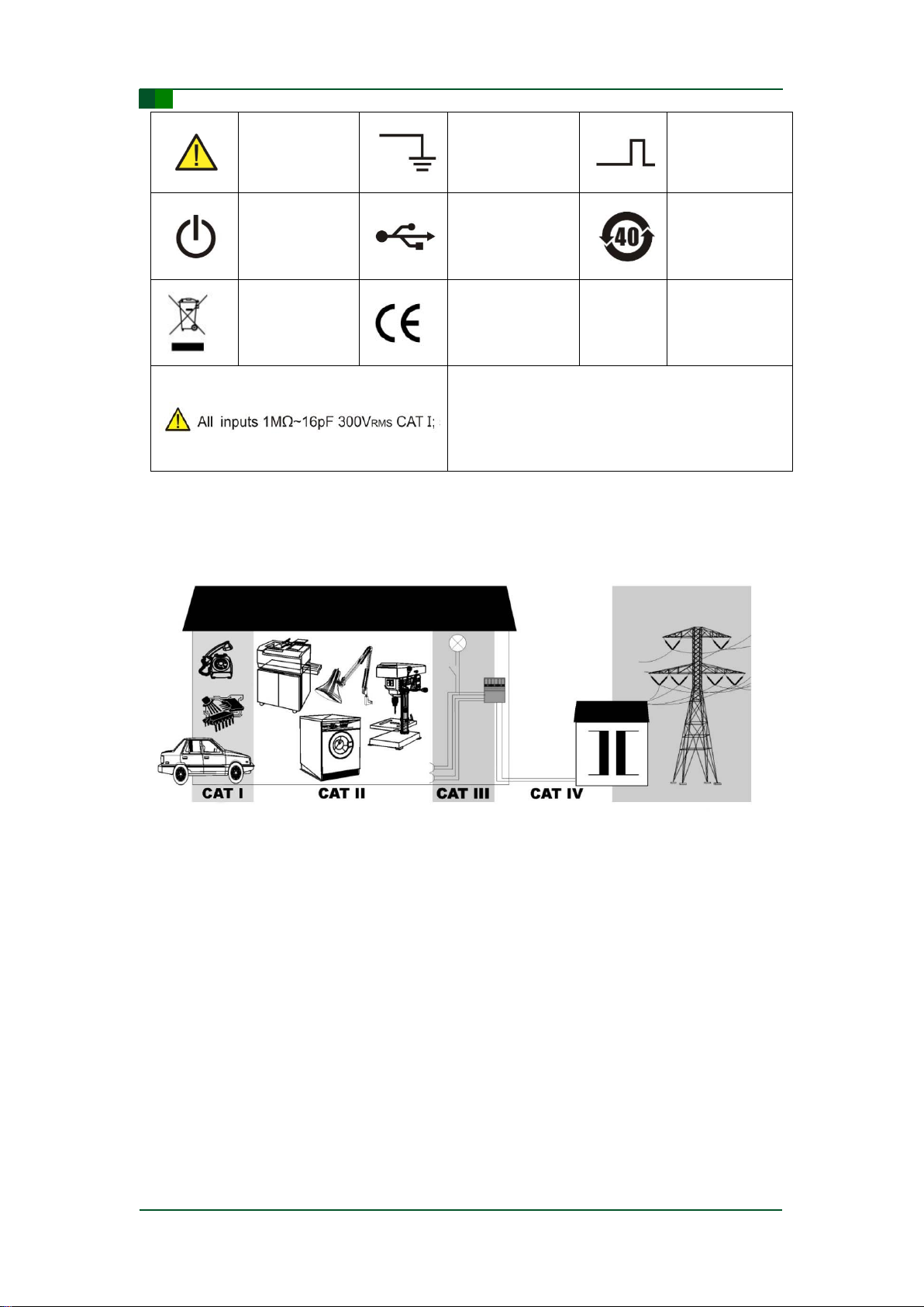
1.2 Warning signs and meanings .............................................................................5
1.3 Measurement Category........................................................................................7
1.4 Instrument Placement..........................................................................................8
1.5 Maintenance and Cleaning..................................................................................8
Chapter 2:Product Introduction..................................................................9
2.1 Main Features of 4-channel ZDS2000B Oscilloscopes....................................9
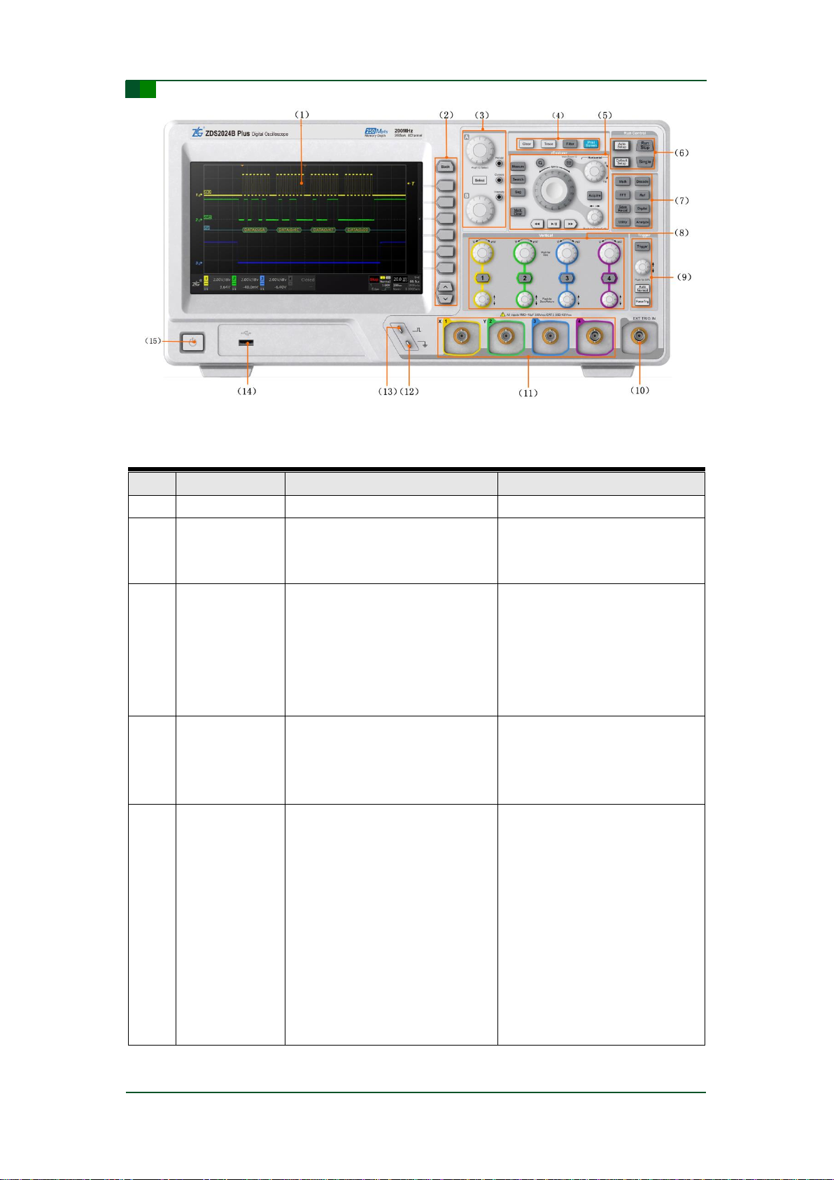
2.2 Panel Introduction................................................................................................9
2.2.1 Front Panel/Rear Panel Description.........................................................................9
Chapter 3:Function Description................................................................13
3.1 z Explore Waveform Zoom................................................................................13
3.1.1 Waveform Zoom ....................................................................................................13
3.1.2 Search and marking................................................................................................15
3.2 Segmented storage funciton.............................................................................16
3.3 Waveform search................................................................................................17
3.4 Parameter measurement ...................................................................................17
3.5 Cursor Measurement .........................................................................................18
3.6 FFT Function.......................................................................................................18
3.7 Protocol Decoding .............................................................................................19
Chapter 4:Technical Parameters for ZDS2000B Series Oscilloscope ...20
4.1 Vertical System...................................................................................................20
4.2 Horizontal System..............................................................................................21
4.3 Sampling System................................................................................................21
4.4 Trigger System....................................................................................................22
4.5 Trigger Type ........................................................................................................22
4.6 Decoding Type....................................................................................................23
4.7 Measurement Parameters..................................................................................25
4.8 Waveform Mathematic Operation.....................................................................26
4.9 Display Characteristics......................................................................................26
4.10 Input/output Port ..............................................................................................27
4.11 Technical Specifications..................................................................................27
4.12 Accessories.......................................................................................................28
Chapter 5:Rights& Statements .................................................................29

3
©2019 Guangzhou ZHIYUAN Electronics
Date: 2019/01/17
User Manual
V1.00
C
Guangzhou ZHIYUAN Electronics Co., Ltd.
ZDS2000B Series Oscilloscope User Manual
Chapter 1:Safe Precautions
The following precautions described herein must be observed during the use of this
instrument. If the instrument is used in a manner not specified in this manual, the
protection provided by the instrument may be impaired. ZHIYUAN Electronics assumes
no liability for the customer’s failure to comply with these requirements.
1.1 General Precautions
In order to avoid injury to operators and damage to the instrument or the devices
connected with the instrument, make sure to comply with the precautions below.
Use correct power cord
Only the dedicated power cord allowed by the country where the instrument is used can
be used. Power cord specifications in mainland: 3×0.75mm2, Ф6.3,IEC 6022753,
L=1500mm. It is used with three-pin plug and has passed CCC certification.
Ground the instrument
The instrument must remain grounded through the protective grounding wire of its
power cord. In order to avoid electric shock, make sure the power cord ground wire is
properly connected with protective earth terminal before connecting any input and
output terminal of the instrument.
Connect probe correctly
The probe’s ground lead is at ground potential. Do not connect it to a high voltage.
Check all ratings before use the instrument
In order to avoid fire and high current impulse, please check all ratings and instructions
of the instrument before use the instrument. For the detail information about all ratings,
please refer to the related user manual.
Use appropriate over voltage protection
In order to avoid the electric shock to operators, make sure an over voltage (such as the
voltage caused by thunderstorm) will not occur.
Do not operate the instrument when the chassis is open
Do not operate the instrument when the chassis is open.
Use the specified power fuse
If the power fuse is necessary to be changed, please return the instrument back to the
factory.The power fuse complied with the specification of this product (Class T,rated
current: 2A, rated voltage: 250V) will be replaced by the maintainer from ZHIYUAN
Electronics.
Avoid exposed circuitry

4
©2019 Guangzhou ZHIYUAN Electronics
Date: 2019/01/17
User Manual
V1.00
C
Guangzhou ZHIYUAN Electronics Co., Ltd.
ZDS2000B Series Oscilloscope User Manual
When the instrument is switched on, do not touch the exposed connections and
components.
Avoid electric shock
Power cord should be inserted into a socket with ground protection on the wall or within
visible area. The socket cannot be used in the overcurrent situation.
When any fault occurs during the use of instrument
When there may be a fault during the use of instrument, please do not remove the
screw of the handle to prevent scratching. If the product has any problem, please stop
operating the instrument immediately and contact ZHIYUAN Electronics in time.
ZHIYUAN Electronics will send engineers to inspect, maintain and adjust it or replace
parts.
Keep instrument ventilated
Inadequate ventilation will cause instrument temperature increase, which may result in
damage to the instrument. Please inspect vent and fan constantly to keep the
instrument ventilated.
Do not use the instrument in a wet environment
In order to avoid the risk of short circuit and electric shock, do not operate the
instrument in a wet environment.
Do not use the instrument in an explosive environment
In order to avoid instrument damage or personal injury, do not operate the instrument in
an explosive environment.
Keep instrument surface clean and dry
To prevent dust or moisture in the air affecting instrument performance, please clean
and dry the surface of instrument.
Electrostatic protection
Static electricity will cause damage to the instrument. The instrument should be tested
in the anti-static area. The internal and external conductors of cables should be
connected to ground to discharge the static electricity before they are connected to the
instrument.
Transportation safety
To avoid damage to the parts (such as keys, knobs or interfaces on the panel) due to
falling of instrument during transportation, please note transportation safety.
The way to use the handle
To ensure the safety of the oscilloscope during use and handling of the oscilloscope,
please follow the method of using the handle.As shown below.

5
©2019 Guangzhou ZHIYUAN Electronics
Date: 2019/01/17
User Manual
V1.00
C
Guangzhou ZHIYUAN Electronics Co., Ltd.
ZDS2000B Series Oscilloscope User Manual
①
②
③
1.2 Warning signs and meanings
CAUTION
CAUTION symbol indicates a hazard. Improper handling or execution in a specified
process, operation and so on can lead to loss of important data or damage to the
instrument. Please completely read and fully understand the related notes before
continuing operation.
The following table lists signs that may be used by the instrument.

6
©2019 Guangzhou ZHIYUAN Electronics
Date: 2019/01/17
User Manual
V1.00
C
Guangzhou ZHIYUAN Electronics Co., Ltd.
ZDS2000B Series Oscilloscope User Manual
Safety Warning
Probe
Compensation
Ground
Probe
Compensation
Input
Power ON/OFF
USBPort
40 years of use,
recyclable
Do not throw the
used battery into
garbage bin.
CE Certification
Each channel has 1MΩ input resistor and 16pF input
capacitor. All inputs are 300Vrms CAT I, i.e., their
maximum voltage should not be greater than 300V
RMS.
(2) Measurement category introduction:
Measurement category includes CATI, CATII, CATIII and CATIV. The main introduction
is shown below.

7
©2019 Guangzhou ZHIYUAN Electronics
Date: 2019/01/17
User Manual
V1.00
C
Guangzhou ZHIYUAN Electronics Co., Ltd.
ZDS2000B Series Oscilloscope User Manual
Measurement
category
Measurement
category
display
Description
Note
I/O
CAT I
It is applicable to measure
for the circuit not directly
connected with main power
supply
Measured for the circuit which is
not supplied by main power
supply or by main supply
especially with internal protection.
II
CAT II
It is applicable to measure
for circuits directly
connected to the
low-voltage device
Measured for household
appliances, portable tools and
other similar devices.
III
CAT III
It is applicable to measure
for building facilities
Measured for the output socket,
industrial device and other
devices of the distribution board,
circuit breaker and wirings include
cable, busbar wire, junction box,
switch and fixed facilities, such as
those stationary motors
permanently attached to fixed
facilities.
IV
CAT IV
It is applicable to measure
for the terminal of the
low-voltage facilities
Measured for primary over current
protection devices and ripple
control units.
Notes: Note: The CAT I result is measured for the circuit not directly connected with main power
supply. For example, a circuit is not supplied by main power supply or by main supply especially
with internal protection. In the latter case, the transient stress is variable. Therefore, users should
know the tolerant transient stress of device.
WARNING
WARNING symbol indicates serious danger. Improper handling or execution in a
specified process, operation and so on can lead to serious or fatal injury to the users.
Please completely read and fully understand the related notes before continuing
operation.
1.3 Measurement Category
ZDS2000B series oscilloscopes can be measured in CAT I, and the maximum input
voltage must be kept in the range of CAT I 300Vrms.
WARNING

8
©2019 Guangzhou ZHIYUAN Electronics
Date: 2019/01/17
User Manual
V1.00
C
Guangzhou ZHIYUAN Electronics Co., Ltd.
ZDS2000B Series Oscilloscope User Manual
The ZDS2000B Plus Series oscilloscopes are only oscilloscopes are only allowed to be
used in the specified measurement category.
1.4 Instrument Placement
CAUTION
The instrument placement location should meet following conditions:
Do not install the instrument in the place in direct sunlight, near heat sources,
strong magnetic field sources, high voltage equipment or power lines, and where
an excessive amount of soot, steam, dust or corrosive gas is present, and where
there is water, oil or chemical.
The instrument should be placed on a flat, even surface; otherwise the
measurement precision may be impaired.
Good ventilation. In order to ensure good ventilation inside the instrument, there
are cooling holes in real panel to avoid high internal temperature; please make
sure the air inlet and vent of the product keep the air flow freely. When using the
oscilloscope on the work bench, please leave at least 10cm gaps on the top,
back and both sides of instrument.
Protection impairment if used in a manner not specified by the manufacturer.
Not to position the equipment so that it is difficult to operate the disconnecting
device.
Warning: Inadequate ventilation may cause temperature increase inside the instrument, thereby
causing the damage to product. Please inspect vent and fan constantly to keep the instrument
ventilated.
1.5 Maintenance and Cleaning
Maintenance
Do not place the instrument in a place exposed to direct sunlight for a long time.
Cleaning
Please clean the instrument as follows:
Cut off power supply.
Use a damp but not dripping soft cloth (with a mild detergent or water) to wipe
the dust outside the instrument. When clean LCD screen, be careful not to scuff
the transparent LCD protective screen.
WARNING
Before the product is powered on, make sure that the product is dry to avoid
unnecessary accidents caused by leaving some moisture.

9
©2019 Guangzhou ZHIYUAN Electronics
Date: 2019/01/17
User Manual
V1.00
C
Guangzhou ZHIYUAN Electronics Co., Ltd.
ZDS2000B Series Oscilloscope User Manual
Chapter 2:Product Introduction
2.1 Main Features of 4-channel ZDS2000B Oscilloscopes
200MHz bandwidth, 2GSa/s sampling rate.
Equipped with 250Mpts mass memory depth.
Equipped with 11 kinds of basic trigger, 22 kinds of protocol trigger and 29 kinds
of protocol decoding.
Equipped with 150K wfm/s waveform refresh rate.
4Mpts FFT analysis function.
51 kinds of true parameters measurement and statistics. Through FPGA full
hardware parallel processing, waveforms in full memory depth can be measured
based on the original sampling point.
Waveform search function. It supports multiple search criteria, such as edge,
pulse width, runt, rising/falling time, period/frequency, and duty cycle. Combined
with “ZOOM” and “Large Knob”function, you can quickly view and locate
abnormal signals.
Waveform play function. In ZOOM mode, use the waveform play function to
quickly browse the whole waveform signal, trends, etc.
Analysis function. ZDS2000B oscilloscope comes with segmented storage
function, Digital filtering function and Wave Analyze waveform comprehensive
analysis software functions, etc. It can help analyze the waveform signal and
locate the problem quickly.
9-inch TFT color touch screen with 800×480 resolution. It has optimized 256
gray levels display.
Support USB Host, USB Device, LAN and RS232 interface as well as SCPI,
which provide rich communication interfaces for secondary programming control.
2.2 Panel Introduction
2.2.1 Front Panel/Rear Panel Description
ZDS2000B series oscilloscope with a touch screen can be operated by using full-screen
touch, and it is easy to operate. Take the ZDS2024B Plus digital oscilloscope as an
example .The front panel of ZDS2024B Plus digital oscilloscope is shown in Figure
2-1,including buttons/knobs and I/O interface, and their functions are described in Table
2-1.

10
©2019 Guangzhou ZHIYUAN Electronics
Date: 2019/01/17
User Manual
V1.00
C
Guangzhou ZHIYUAN Electronics Co., Ltd.
ZDS2000B Series Oscilloscope User Manual
Figure 2-1: The front panel of ZDS2024B Plus oscilloscope
Table 2-1: Front Panel Function Introduction
No.
Name
Description
Use Introduction
(1)
LCD
LCD with touch screen.
9-inch color display screen.
(2)
Menu function
keys
These keys perform operations of
the menus in the display.
Long press the soft keys to pop-up
the explanation of the options in
menu selection.
(3)
Multifunctional
knobs
These knobs are mainly used for
the selection and adjustment of the
menu, cursor, waveform brightness
and afterglow time, as well as the
adjustment of MATH and REF
waveform.
The knobs can be turned
clockwise or counter clock
wise .Knob A and knob B mainly
perform menu selection, or Knob A
performs fine tune and Knob B
performs coarse tune.
(4)
Shortcut
function keys
These keys are mainly used to
perform One-key clearing, One-key
persistence, One-key capture and
FIR hardware filtering function.
Belongs to the key operation.
Long press the soft keys to pop-up
the explanation of the options in
menu selection.
(5)
Waveform
detection area
Waveform detection area is mainly
used for waveform measurement,
search, waveform marker,
waveform scaling and segment
storage function;
The horizontal control area is used
for the adjustment of the horizontal
time base of the waveform/zoom
window, and the adjustment of the
horizontal offset of the waveform
/zoom window
In the zoom status, it is used for
the adjustment of the zoom
window and waveform by the large
knob and horizontal knob .The
knobs can be turned clock wise or
counterclockwise. The large knob
can adjust time base, and the
small knob can adjust horizontal
offset.

11
©2019 Guangzhou ZHIYUAN Electronics
Date: 2019/01/17
User Manual
V1.00
C
Guangzhou ZHIYUAN Electronics Co., Ltd.
ZDS2000B Series Oscilloscope User Manual
续上表
No.
Name
Description
Use Introduction
(6)
Run Control
keys
These keys are used to start or
stop data acquisition, set
oscilloscope measurement
automatically, and restore the
oscilloscope’s default settings.
Belongs to the key operation.
(7)
Multifunctional
control area
The keys in this area are used to
perform Decode, Digital, Math and
Ref functions.
Belongs to the key operation.
(8)
Vertical control
area
This area is used to offset and
zoom waveforms vertically.
The knobs can be turned
clockwise or counterclockwise.
The large knob can adjust the
vertical sensitivity, and the small
knob can adjust the vertical offset.
(9)
Trigger control
area
This area sets the triggering
function.
The knobs can be turned
clockwise or counterclockwise.
(10)
External trigger
input
It is used to input external trigger
signals.
Note: The maximum input voltage
is 150Vrms
Connecting mode: Make the BNC
female of the external interface
connected with the BNC terminal
of the oscilloscope. Turn the knob
to right and lock it.
(11)
Analog channel
input terminal
These inputs are connected with
analog signals to be measured.
Note: The maximum input voltage
is 150Vrms.
Connecting mode: Make the BNC
female of the probe connected
with the BNC terminal of the
oscilloscope. Turn the knob to
right, and these two interfaces
stuck means the connection is
successful.
(12)
Probe
compensation
signal ground
terminal
Ground terminal
Make the crocodile clip of the
probe connected with ground
terminal. It means the ground
connection is successful.
(13)
Probe
compensation
signal output
terminal
This terminal outputs a 1kHz, 3Vpp
square wave signal.
Make the hook of the probe
connected with the output
terminal.
(14)
USB host port
This port is for connecting USB
storage devices.
Make the standard Atype USB
directly plugged into the USB host
port for use.
(15)
Power switch
Press once to switch power on;
press again to switch power off.
Key operation.
Notes: All soft keys are lighted up when the instrument is turned on, and the keys become gray
when the instrument is not in used.

12
©2019 Guangzhou ZHIYUAN Electronics
Date: 2019/01/17
User Manual
V1.00
C
Guangzhou ZHIYUAN Electronics Co., Ltd.
ZDS2000B Series Oscilloscope User Manual
Figure 2-2 shows the real panel of ZDS2024B Plus oscilloscope.
Figure 2-2: Real Panel of ZDS2024B Plus Oscilloscope
Kensington lock: The oscilloscope can be locked on a fixed position by using
Kensington lock as follows: insert the lock into the Kensington lock hole on the real
panel, turn the key clockwise to lock the instrument, and then remove the key. Please
note that do not insert any other things into the lock hole to prevent the instrument from
damage.
Notes: Adjustable bracket: Adjust the supporting feet appropriately and use them as the bracket
to make the oscilloscope upward sloping, so as to leave the oscilloscope stableness for better
operation and observing the display screen. Open the supporting feet outward to leave the
oscilloscope sloping or close the feet inward to leave the oscilloscope upright.
Trigger output: Make the BNC female interface connected with the trigger output interface. Then
turn the knob clock wise .These two interfaces stuck means the connection is successful.
RS232 interface: This interface can be used for the serial port.
LAN interface: Make the network cable interface connected with the LAN interface.
USB Device: Make the standard B type USB serial cable connected with the USB Device interface
for use.
AC power jack: Make the power line which is complied with the provision connected with the power
interface. (See "General Precautions").

13
©2019 Guangzhou ZHIYUAN Electronics
Date: 2019/01/17
User Manual
V1.00
C
Guangzhou ZHIYUAN Electronics Co., Ltd.
ZDS2000B Series Oscilloscope User Manual
Chapter 3:Function Description
3.1 z Explore Waveform Zoom
Large data storage can realize long-time waveform capture while maintaining a high
sampling rate and the waveform is guaranteed not to be distorted. However, our
purpose is not only to obtain waveforms without any distortion, but also use an
oscilloscope to automatically and conveniently analyze the abnormality in waveforms,
enabling users to locate abnormal signals within millions of waveforms without any
effort.
Figure 3-1: zExplore Panel
3.1.1 Waveform Zoom
The waveform zoom function can display not only the whole waveform but also the
details of a waveform. ZDS2000B series oscilloscope can use high-speed parallel
processing capability of powerful multi-chip FPGA array to realize the zoom mode in
the case of real-time massive data response.
Press “Waveform Zoom”button to enter the waveform zoom interface, as shown in
Figure 3-2.
Figure 3-2: Waveform zoom

14
©2019 Guangzhou ZHIYUAN Electronics
Date: 2019/01/17
User Manual
V1.00
C
Guangzhou ZHIYUAN Electronics Co., Ltd.
ZDS2000B Series Oscilloscope User Manual
The display screen is divided into two parts. The upper half part is the normal display
view, also called main time base; and the lower half part is the zoom display view,
also called secondary time base, which is a magnified display of the specified area of
a waveform in the normal display view.
(1) Horizontal time-base adjustment of a waveform in the zoom mode
The waveform selected in the “blue”box is adjusted after entering the zoom mode. If
the normal view mode is selected, users can expand or compress the waveform in
the horizontal direction; if the zoom view mode is selected, users can adjust the size
of zoom window to view the waveform details.
Figure 3-3: Horizontal control area
(2) Waveform translation in the zoom mode
The large knob and time base offset knob are used to adjust the offset of main time
base waveform or secondary time base zoom window so that user can observe the
waveforms at different positions, as shown in Figure 3-4.
Figure 3-4: Waveform/zoom window translation
The large knob is used to quickly move main time base waveforms and secondary
time base zoom windows. The wider the range of the large knob is turned, the faster
the zoom window moves. The horizontal offset knob is used to slowly move main time
base waveforms and secondary time base zoom windows.
(3) Waveform play/pause
When the memory depth is large, much waveform data can be recorded, but the
whole waveform signal may not be observed completely. However, user can press

15
©2019 Guangzhou ZHIYUAN Electronics
Date: 2019/01/17
User Manual
V1.00
C
Guangzhou ZHIYUAN Electronics Co., Ltd.
ZDS2000B Series Oscilloscope User Manual
the “Waveform play/pause”button of ZDS2000B series oscilloscope to automatically
play and move the secondary time base waveform in the zoom mode, as shown
inFigure 3-5.
Turn the “large knob”to adjust the play speed of waveform. Faster and wider
range the large knob is turned, faster the waveform is played. The speed can
reach its maximum value.
Reversely turn the “large knob”to change the play direction of waveform. When
the zoom window moves to the left, the waveform passes through the window
from left to right, and users will observe the waveform moves to the right in the
secondary time base; on the contrary, the waveform moves to the left.
Press the navigation but ton with the same direction as the secondary time base
waveform play to increase the waveform play speed. The more times the button
is pressed, the faster the waveform is played. Press the backward navigation
button to decrease the waveform play speed. The more times the button is
pressed, the slower the waveform is played. When the speed is reduced to 0, the
waveform will be played in the opposite direction.
Press the “Waveform play/pause”button again to stop the movement of
waveform temporarily.
Figure 3-5: Waveform play/pause
3.1.2 Search and marking
The “search”function can quickly find the interested waveform signals and then mark
them automatically for user to view these signals later conveniently. It provides many
search conditions, including edge, pulse width, rising/falling time, cycle, frequency,
duty cycle, runt, etc.
The “marking”function divides into manual marking and automatic marking. It can
mark the position of interested waveform in the sampled waveforms and quickly
locate the abnormal signal.

16
©2019 Guangzhou ZHIYUAN Electronics
Date: 2019/01/17
User Manual
V1.00
C
Guangzhou ZHIYUAN Electronics Co., Ltd.
ZDS2000B Series Oscilloscope User Manual
Figure 3-6: Waveform search/marking
When using the manual marking function, users can press [Mark/Clear] button at the
position of the interested waveform to mark it, and then press this button again to
delete the marking. Press the left or right navigation button to jump from one marking
position to the other.
3.2 Segmented storage funciton
The segmented storage is triggered several times in the process of acquisition, and
the sampled data for each trigger are stored in the individual segment of storage
space.
There is no waveform appearing in the signal for a long time, and then the waveform
appears along with interference, as shown in Figure 3-7. In order to facilitate analysis
and save storage space, the segmented storage is used to record each section of
waveform under triggering conditions. After the waveform is captured, users can use
the left and right navigation buttons to perform abnormality analysis and processing
for each section of waveform.
Figure 3-7: Segmented storage application
The total memory depth is divided into n segments, as shown in Figure 3-8. The first
segment is used for display, and the second segment begins to be used for storage,
that is, the sampled data is stored in the second segment when the first triggering
occurs; after the second segment is full, the first triggering ends and users should
wait for the arrival of the second triggering; and then the sampled data is stored into
the third segment when the second triggering occurs; and so on.

17
©2019 Guangzhou ZHIYUAN Electronics
Date: 2019/01/17
User Manual
V1.00
C
Guangzhou ZHIYUAN Electronics Co., Ltd.
ZDS2000B Series Oscilloscope User Manual
Figure 3-8: Segmented storage structure diagram
Take the ZDS2024B Plus oscilloscope for example; its total memory depth is
250Mpts. The number of allocated segments is calculated as follows:
N=250 * 1024 * 1024 / (the current storage capacity is rounded to the nth power of
2) –1.
3.3 Waveform search
ZDS2000B series oscilloscope has powerful real-time hardware search function. It
provides many waveform search modes, including edge, pulse width, cycle,
frequency, rising/falling time, duty cycle and runt, and sets the measuring modes in
detail, such as greater than, less than, within the range and outside the range.
ZDS2000B is also able to quickly locate the interested signal, greatly improving the
efficiency of abnormal signal measuring and analyzing.
Figure 3-9: Waveform search
3.4 Parameter measurement
ZDS2000B series oscilloscope has powerful parameter measurement and statistics
function. It uses full hardware to accelerate processing, can analyze all original

18
©2019 Guangzhou ZHIYUAN Electronics
Date: 2019/01/17
User Manual
V1.00
C
Guangzhou ZHIYUAN Electronics Co., Ltd.
ZDS2000B Series Oscilloscope User Manual
(non-sampling) sample points on the whole screen, and perform the measurement
and statistics of 51 parameters simultaneously. The processing speed is extremely
fast.
Figure 3-10: Automatic measurement interface
3.5 Cursor Measurement
Users can use the cursor measurement function to measure the X axis values (such
as time) and Y axis values (such as voltage) of selected waveforms. There are two
pairs of measurement cursors: X-type cursor or Y-type cursor. The X-type cursor is
generally used to measure time parameters and Y-type cursor is generally used to
measure voltage parameters, as shown in Figure 3-11.
Figure 3-11: X-type cursor and Y-type cursor
3.6 FFT Function
Users can use FFT function to compute the Fast Fourier Transform. It is used to find

19
©2019 Guangzhou ZHIYUAN Electronics
Date: 2019/01/17
User Manual
V1.00
C
Guangzhou ZHIYUAN Electronics Co., Ltd.
ZDS2000B Series Oscilloscope User Manual
crosstalk problems, locate distortion problems caused by the non-linearity of amplifier
in the analog waveform, or adjust the analog filter.
Figure 3-12: FFT interface view
3.7 Protocol Decoding
Users can easily find the communication error, debug hardware and accelerate the
development progress through this function, as shown in Figure 3-13. ZDS2000B
series oscilloscope can perform 27 protocols decoding for the input signals of 4
analog channels (CH1-CH2-CH3-CH4), including UART, SPI, I2C, CAN-FD, CAN,
Flex Ray, USB, Wiegand, LIN and other commonly used protocols.
Triggering position
IIC clock line SCL
IIC data line SDA
IIC decoding line
IIC decoding event list
Turn knob B to
view all decoding
events
Figure 3-13: Decoding function view

20
©2019 Guangzhou ZHIYUAN Electronics
Date: 2019/01/17
User Manual
V1.00
C
Guangzhou ZHIYUAN Electronics Co., Ltd.
ZDS2000B Series Oscilloscope User Manual
Chapter 4:Technical Parameters for
ZDS2000B Series Oscilloscope
All parameters can be guaranteed, but the oscilloscope must be operated
continuously under the operating temperature for more than 30 minutes.
4.1 Vertical System
Figure 4-1: Theanalogchannelofvertical system
Characteristics
Description
ZDS2022B Plus
ZDS2024B Plus
Number of channels
2
4
Analog bandwidth (-3dB)
200MHz
200MHz
Calculated rising time
≤1.75ns
≤1.75ns
Vertical resolution
8 bit
Bandwidth limit
20MHz、OFF
Input coupling
DC、AC、GND
Input impedance
1MΩ ±1% || 16pF ±4pF
Input sensitivity range
2mV/div ~10V/div,1-2-5stepping
Maximum Input Voltage
(1MΩ)
CAT I 300Vrms
DC Gain accuracy
2 mV/div ~5 mV/div :±3% full scale
10 mV/div ~ 10 V/div:±2% full scale
DC Offset accuracy
-2V≤ offset value ≤2V :±0.1 div±2 mV ±2% offset value
offset value>2V,offset value<-2V:±0.1 div±2 mV ±3% offset value
Interchannel isolation
>40dB
Low-frequency response
(AC coupling,-3dB)
≤5Hz
Offset range
2mV/div~ 50mV/div:±2V
100mV/div ~ 10V/div:±40V
Dynamic range
Screen center ±6div
Probe attenuation
coefficient
0.1×~1000×,1-2-5 stepping
Table of contents