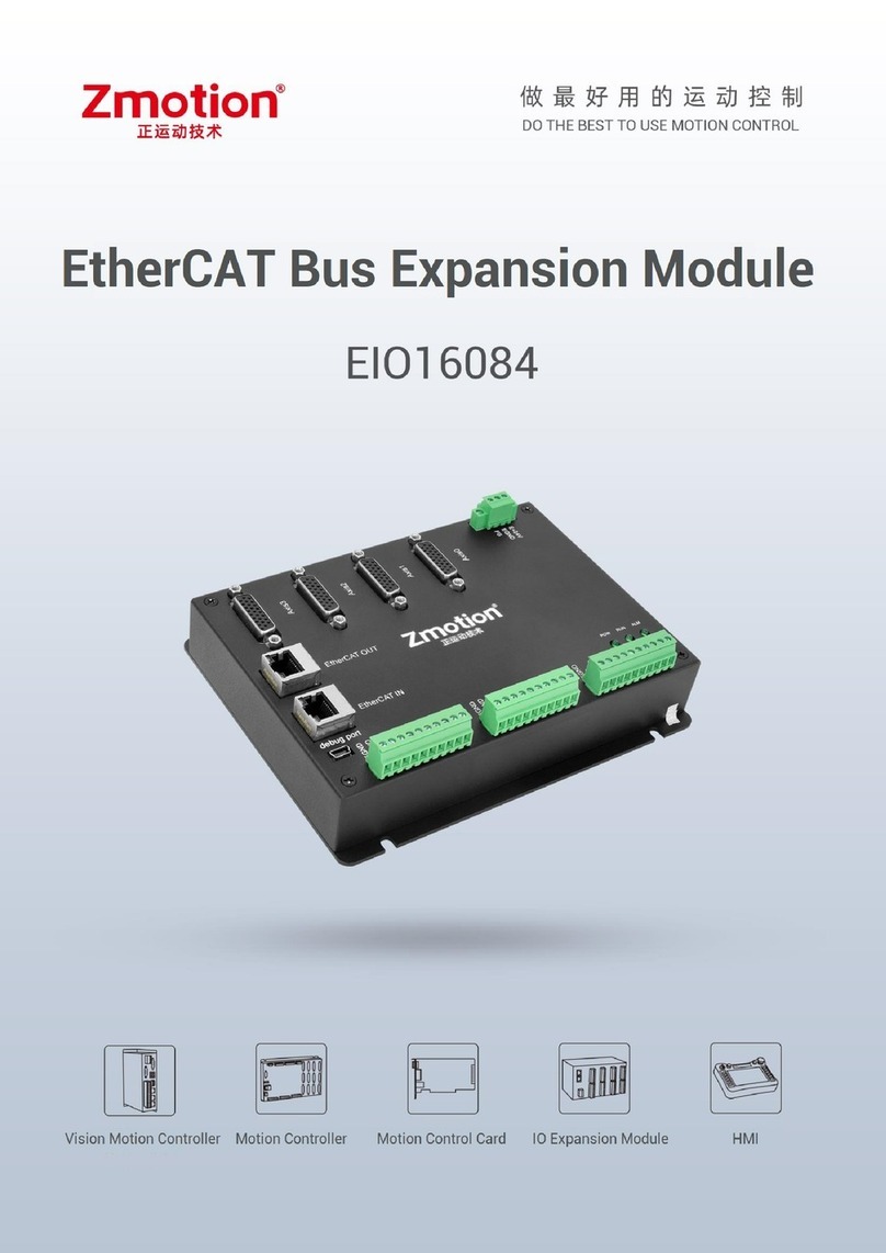
Zmotion EIO24088 User manual

EIO24088 Bus Expansion Card Manual Version 1.1
1
EIO24088 Bus Expansion Card
Hardware Manual
Version 1.1

EIO24088 Bus Expansion Card Manual Version 1.1
2
Copyright statement
This manual is copyrighted by Shenzhen Technology Co., Ltd.,
without the written permission of the Zmotion Technology, no person
shall reproduce, translate and copy any content in this manual.
EIO controller software involved in details as well as the
introduction and routines of each instruction, please refer to ZBASIC
software manual.
Information contained in this manual is only for reference. Due to
improvements in design and functions and other aspects, Zmotion
Technology reserves the final interpretation! Subject to change without
notice!
Pay attention to safety when debug the machine! Be sure to
design effective safety devices in the machine, and add the error
handling procedures in software. Zmotion has no obligation or
responsibility for the loss.

EIO24088 Bus Expansion Card Manual Version 1.1
3
Content
EIO24088 Bus Expansion Card Hardware Manual ..........................................................................1
Chapter I Control Card Introduction .................................................................................................4
Chapter II Hardware Description ......................................................................................................4
2.1 EIO24088............................................................................................................................5
2.1.1 Power Interface ........................................................................................................5
2.1.2 Power, Input, Output wiring reference.....................................................................6
2.1.3 General Input Signal ................................................................................................6
2.1.3.1 Input 0-7........................................................................................................6
2.1.3.2 Input 8-15......................................................................................................7
2.1.3.3 Input 16-23....................................................................................................7
2.1.4 Output/IO Signal......................................................................................................8
2.1.4.1 Output 0-7 .....................................................................................................8
2.1.5 Axis Interface ...................................................................................................................9
2.1.6 Axis Wiring Reference...................................................................................................10
2.1.6.1 Wiring Reference for Low-speed Differential Pulse ...................................10
2.1.6.2 Wiring Reference for High-speed Differential Pulse ..................................12
2.1.6.3 Wiring Reference for Encoder Axis ............................................................14
2.1.7 IO Start Number Configuration .....................................................................................15
2.1.8 Data Dictionary..............................................................................................................16
Chapter III Common Problems .......................................................................................................18
Chapter IV Hardware Installation ...................................................................................................19
4.1 EIO24088 Installation Size ...............................................................................................19

EIO24088 Bus Expansion Card Manual Version 1.1
4
Chapter I Control Card Introduction
ZMC is the abbreviation of motion controller model launched by ZMOTION
technology. Zmotion motion controllers can be applied in all kinds of online or offline
occasions.
EIO expansion module is used for EtherCAT bus controller, when IO and other
resources are not enough, an expansion module is needed. And controller can link with
multi expansion modules through bus at the same time, and each expansion module has
a unique address, which starts from 0. The resource of expansion module can be
accessed by program on controller through IO number, and this number is set through
bus instruction NODE_IO.
Chapter II Hardware Description

EIO24088 Bus Expansion Card Manual Version 1.1
5
2.1 EIO24088
➢EIO24088 has 8 pulse axes, 24 general inputs and 8 general outputs.
➢EIO24088 has 2 EtherCAT bus interfaces, one connects with the master controller,
another connects with drive equipment or next level expansion board.
2.1.1 Power Interface
Pin No.
Name
Description
1
EARTH
Shield
2
EGND
Internal power
3
+24V
Internal power 24V input
EIO24088 is supplied power by single power.

EIO24088 Bus Expansion Card Manual Version 1.1
6
2.1.2 Power, Input, Output wiring reference
2.1.3 General Input Signal
2.1.3.1 Input 0-7
PIN
Name
Description
1
EGND
Signal ground
2
EGND
Signal ground
3
IN0
Input 0
4
IN1
Input 1
5
IN2
Input 2

EIO24088 Bus Expansion Card Manual Version 1.1
7
6
IN3
Input 3
7
IN4
Input 4
8
IN5
Input 5
9
IN6
Input 6
10
IN7
Input 7
2.1.3.2 Input 8-15
PIN
Name
Description
1
EGND
Signal ground
2
EGND
Signal ground
3
IN8
Input 8 (EL0-)
4
IN9
Input 9 (EL0+)
5
IN10
Input 10 (EL1-)
6
IN11
Input 11 (EL1+)
7
IN12
Input 12 (EL2-)
8
IN13
Input 13 (EL2+)
9
IN14
Input 14 (EL3-)
10
IN15
Input 15 (EL3+)
2.1.3.3 Input 16-23
PIN
Name
Description
1
EGND
Signal ground
2
EGND
Signal ground
3
IN8
Input 16 (EL4-)
4
IN9
Input 17 (EL4+)
5
IN10
Input 18 (EL5-)
6
IN11
Input 19 (EL5+)
7
IN12
Input 20 (EL6-)

EIO24088 Bus Expansion Card Manual Version 1.1
8
8
IN13
Input 21 (EL6+)
9
IN14
Input 22 (EL7-)
10
IN15
Input 23 (EL7+)
2.1.4 Output/IO Signal
2.1.4.1 Output 0-7
PIN
Name
Description
1
IOGND
Signal Ground
2
NC
Blank
3
OUT0
Output 0
4
OUT1
Output 1
5
OUT2
Output 2
6
OUT3
Output 3
7
OUT4
Output 4
8
OUT5
Output 5
9
OUT6
Output 6
10
OUT7
Output 7

EIO24088 Bus Expansion Card Manual Version 1.1
9
2.1.5 Axis Interface
◼It provides 0V and +5V, which can provide 5V power for the encoder.
◼Do set its parameter ATYPE before use axis.
PIN
Signal
Description
1
EGND
External power
2
IN24-31/ALM
General input, recommended as drive alarm
3
OUT8-15/ENABLE
General output, recommended as drive enable
4
EA-
Encoder input
5
EB-
Encoder input
6
EZ-
Encoder input
7
+5V
Digital ground
8
Reserved
Reserved
9
DIR+
Servo/stepper directional output
10
GND
Digital ground
11
PUL -
Servo/stepper pulse output
12
Reserved
Reserved
13
GND
Digital ground
14
OVCC
E24V output (recommended only for IO servo)
15
Reserved
Reserved
16
Reserved
Reserved
17
EA+
Encoder input
18
EB+
Encoder input
19
EZ+
Encoder input

EIO24088 Bus Expansion Card Manual Version 1.1
10
20
GND
Digital ground
21
GND
Digital ground
22
DIR-
Servo/stepper directional output
23
PUL+
Servo/stepper pulse output
24
GND
Digital ground
25
Reserved
Reserved
26
Reserved
Reserved
It can be configured enable or alarm directly through data dictionary, the default
can’t use, but needs master controller to use.
2.1.6 Axis Wiring Reference
2.1.6.1 Wiring Reference for Low-speed Differential Pulse
Differential Connection

EIO24088 Bus Expansion Card Manual Version 1.1
11
Single-ended Connection
Controller and Panasonic A5 servo drive low-speed differential pulse wiring reference
If connects with high-speed differential pulse or encoder, GND must be connected
with 25th GND of drive together.

EIO24088 Bus Expansion Card Manual Version 1.1
12
2.1.6.2 Wiring Reference for High-speed Differential Pulse
If the low-speed differential pulse meets speed requirement, use low-speed
differential pulse preferentially. Or if need to use high-speed differential pulse, do
connect internal digital GND of controller with GND of high-speed pulse interface
of drive.
High-speed Differential Pulse Connection

EIO24088 Bus Expansion Card Manual Version 1.1
13
Controller and Panasonic A5 servo drive high-speed differential pulse wiring reference

EIO24088 Bus Expansion Card Manual Version 1.1
14
2.1.6.3 Wiring Reference for Encoder Axis
Encoder connection
Some servo drives are not optocoupler isolation, now the internal GND of
controller must be linked with GND of drive together. Most drive encoders are not
optocoupler isolation, when connects with encoder, internal GND of controller must be
linked with GND of encoder together.

EIO24088 Bus Expansion Card Manual Version 1.1
15
2.1.7 IO Start Number Configuration
Local IO of EIO24088 is mapped into master controller through NODE_IO
Grammar: NODE_IO (slot, node) = iostart
slot
the bus slot number of controller, default is 0
node
Device number, start from 0, 0-
iostart
IO start number to be set, input and output start numbers
of single equipment are the same.
Note: IO start number of NODE_IO instruction only can be set to multiples of 8,
like, 0, 8, 16, 32, etc. If iostart inputs 30, means it should be set as 24. If expanded
IO number and controller itself IO repeat, they become invalid simultaneously, so
it is not recommended. Firstly, check the controller status to know the local IO
maximum value of controller exactly, then use NODE_IO instruction.
Local input 24-31 can configure as drive ALM signal, but it is recommended to
configure as alarm signal through master controller ALM_IN instruction.
Local output 8-15 can configure as drive automatic enable signal, or enable through
master controller OP instruction directly. After it is configured automatic enable,
master controller can’t control relative output port directly.

EIO24088 Bus Expansion Card Manual Version 1.1
16
2.1.8 Data Dictionary
→Input and Output:
Number
Description
Type
Read/write
Others
6000h
Input
ARRAY U8
RO
1-close
6200h
Output
ARRAY U8
RW
1-open
6206h
Abnormal output
mode
ARRAY U8
RW
1-use abnormally
output
6207h
Abnormal output
usage status
ARRAY U8
RW
→The first drive:
Number
Description
Type
Read/write
Others
6011h
Atype
UNSIGNED8
RW
Axis type of expansion
board:
⚫0: virtual axis
⚫1: step or servo of pulse
directional
⚫2: servo of analog signal
control
⚫3: orthogonal encoder
⚫4: step + encoder
⚫5: step + pulse
directional encoder
⚫6: pulse directional
encoder
7: pulse directional
step/servo + EZ signal input

EIO24088 Bus Expansion Card Manual Version 1.1
17
6012h
Invert_Step
UNSIGNED16
RW
See controller introduction
Invert_Step
6013h
Iolevel
UNSIGNED32
RW
B0-origin electrical level
B1-limit position level
B8-automatic use enable
signal
B9-use ALM signal to alarm
B11-B15: origin selection
signal
6014h
Axisstatus
UNSIGNED32
RO
See controller introduction
AXISSTATUS
6040h
Controlword
UNSIGNED16
RW
Relative master controller
DRIVE_CONTROLWORD:
B0- Switch on
B1- Enable voltage
B3- Enable operation
B7- Fault reset
6041h
Statusword
UNSIGNED16
RO
Relative master controller
DRIVE_STATUS:
B0 Ready to switch on
B1 Switch on
B2 Operation enabled
B3 Fault
B4 Voltage enabled
B5 Quick stop
B7 Warning

EIO24088 Bus Expansion Card Manual Version 1.1
18
B8 EZ status
B9 Remote
B10 Target reached
B11 Internal limit active
B12-13 Operation mode
specific B14 EA status
B15 EB status
6060h
Modes of
operation
INTEGER 8
RW
6: home the origin port
8: cycle location
607Eh
Polarity
INTEGER 8
RW
1- opposite direction
0- normal direction
60fDh
Drive input
compatibility
UNSIGNED
32
RW
The second drive configuration is incremented by 800h relative to the first, and
the other drives are incremented sequentially.
Chapter III Common Problems
Problem
Suggestion
No signal of input can be detected
Check whether IO power supplies or not
Check whether signal electric level is matched with
input or not
Output has no reaction when it
operates
Check whether power supplies or not
IO board also should supply IO power.

EIO24088 Bus Expansion Card Manual Version 1.1
19
Chapter IV Hardware Installation
4.1 EIO24088 Installation Size
Unit:mm mounting hole diameter 4.5mm
Table of contents
Other Zmotion Computer Hardware manuals
Popular Computer Hardware manuals by other brands

DFI
DFI ADN553 user manual

Cypress Semiconductor
Cypress Semiconductor CY25822-2 Specification sheet

Alphacool
Alphacool NexXxoS GPX-A 280 M08 instruction manual

Texas Instruments
Texas Instruments OMAP-L137 EVM user manual

Cypress
Cypress CYSMART CY5677 Installation

Intel
Intel BFCBASE - Motherboard - 7300 datasheet

Apricorn
Apricorn PEDA Specifications

ICP DAS USA
ICP DAS USA VXC-114U Series Quick start guide for

Terasic
Terasic Cypress CapSense P0080 user manual

Cypress Semiconductor
Cypress Semiconductor CY7C1410AV18 Specification sheet

Honeywell
Honeywell PX4ie installation guide

ekwb
ekwb EK-FC WX9100 PRO BACKPLATE installation manual