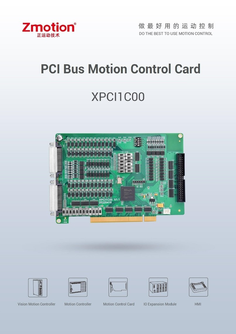
Zmotion XPCI1400 User manual


Foreword
The motion controller provides rich interface, and it has excellent motion control performance, which
can meet the expansion requirements of various projects.
This manual is copyrighted by Shenzhen Technology Co., Ltd., without the written permission of the
Zmotion Technology, no person shall reproduce, translate and copy any content in this manual. The
above-mentioned actions will constitute an infringement of the copyright of the company's manual, and
Zmotion will investigate legal responsibility according to law.
For details about the ZMC controller software and the introduction and routine of each command,
please refer to the ZBASIC software manual.
Information contained in this manual is only for reference. Due to improvements in design and
functions and other aspects, Zmotion Technology reserves the final interpretation! Subject to change
without notice!
Pay attention to safety when debugging the machine!
Please be sure to design an effective safety protection device in the machine, and add an error
handling program in the software, otherwise Zmotion has no obligation or responsibility for the loss
caused.
In order to ensure the safe, normal and effective use of the product, please be sure to read this
product manual carefully before installing and using the product.

Safety Statement
⚫This chapter describes the safety precautions required for the correct use of this product. Before
using this product, please read the instructions for use and correctly understand the relevant
information on safety precautions.
⚫This product should be used in an environment that meets the design specifications, otherwise
it may cause equipment damage or personal injury, and malfunctions or component damage
caused by failure to comply with relevant regulations are not within the scope of product quality
assurance.
⚫Zmotion will not take any legal responsibility for personal safety accidents and property losses
caused by failure to comply with the contents of this manual or illegal operation of products.
Safety Level Definition
According to the level, it can be divided into " Danger " and " Caution ". Failure to operate as required
may result in moderate injury, minor injury or equipment damage.
Please keep this guide in a safe place for reading when needed, and be sure to hand this manual to
the end user.
Install
Danger
◆When the controller is disassembled, all external power supplies used by the
system should be disconnected before operation, otherwise it may cause
misoperation or damage to the equipment.
◆It is forbidden to use in the following places: places with dust, oil fume, conductive
dust, corrosive gas and flammable gas; places exposed to high temperature,
condensation, wind and rain; places with vibration and shock. Electric shock, fire
and misuse can cause product damage and deterioration.
Notice
◆Avoid metal shavings and wire ends falling into the hardware circuit board during
installation.
◆After installation, ensure that there are no foreign objects on the hardware circuit
board.
◆When installing, make it tightly and firmly with the mounting frame.

◆Improper installation of the controller may result in misoperation, failure and fire.
Wiring
Danger
◆The specifications and installation methods of the external wiring of the
equipment shall comply with the requirements of local power distribution
regulations.
◆When wiring, all external power supplies used by the system should be
disconnected before operation.
◆When powering on and running after the wiring work is completed, the terminals
attached to the product must be installed.
◆Cable terminals should be well insulated to ensure that the insulation distance
between cables will not be reduced after the cables are installed on the terminal
block.
Notice
◆Avoid metal shavings and wire ends falling into the hardware circuit board during
installation.
◆The cable connection should be carried out correctly on the basis of confirming
the type of the connected interface.
◆It should be confirmed that the cables pressed into the terminals are in good
contact.
◆Do not bundle the control wires and communication cables with the main circuit
or power supply wires, etc., and the distance between the wires should be more
than 100 mm, otherwise noise may cause malfunction.
◆If the controller is not installed properly, it may cause electric shock or equipment
failure or malfunction.

XPCI1400 Motion Control Card User Manual V1.0
Content
Chapter I Production Information........................................................................................3
1.1. Product Information ..........................................................................................3
1.2. Function Features..............................................................................................3
1.3. System Frame ...................................................................................................4
1.4. Model Information.............................................................................................4
1.5. Hardware Installment........................................................................................5
Chapter II Product Specification .........................................................................................7
2.1. Basic Specification............................................................................................7
2.2. Interface Definition............................................................................................7
2.3. Work Environment .............................................................................................8
Chapter III Wiring, Communication Configuration ..............................................................9
3.1. Power Input .......................................................................................................9
3.2. X300 Signal Interface........................................................................................9
3.2.1. ACC68 Adapter .....................................................................................10
3.2.2. Terminal Definition ...............................................................................10
3.3. X301 Signal Interface......................................................................................13
3.3.1. ACC68 Adapter .....................................................................................13
3.3.2. Terminal Definition ...............................................................................14
3.4. Pulse Directional Output .................................................................................16
3.4.1. Pulse Direction Axis Specification & Wiring.........................................16
3.4.2. Basic Usage Method ............................................................................17
3.5. IN: Digital Input................................................................................................19
3.5.1. Digital Input Specification & Wiring .....................................................19
3.5.2. Position Sensor & Signal Distribution..................................................22
3.5.3. Basic Usage Method ............................................................................22
3.7. OUT: Digital Output..........................................................................................23

XPCI1400 Motion Control Card User Manual V1.0
3.7.1. Digital Output Specification & Wiring...................................................23
3.7.2. Basic Usage Method ............................................................................24
3.8. DIP Switch .......................................................................................................25
3.8.1. Differential/Single-ended DIP Switch ..................................................25
3.8.2. S200, S201 DIP Switch.........................................................................26
Chapter IV Accessories .....................................................................................................28
4.1. Standard Accessories .....................................................................................28
4.2. Optional Accessories ......................................................................................29
Chapter V Installation........................................................................................................31
5.1. XPCI1400 Installation......................................................................................31
5.2. Drive Program Installation ..............................................................................31
5.3. Ordinary Network Card Install EtherCAT Bus Protocol ...................................37
Chapter VI Program & Applications...................................................................................42
6.1. ZDevelop Software Usage...............................................................................42
6.2. PC Upper-Computer Program Application .....................................................47
Chapter VII Run and Maintain ...........................................................................................50
7.1. Regular Inspection and Maintenance .............................................................50
7.2. Common Problems..........................................................................................51

XPCI1400 Motion Control Card User Manual V1.0
Chapter I Production Information
1.1. Product Information
XPCI motion control card is a kind of new type PCI bus control card. It can control
multiple step motors or digital servo motors. And there are many functions on it, such as,
multi-axis point to point motion, interpolation, trajectory planning, IO control, etc.
1.2. Function Features
◆4 axes motion control at most.
◆Pulse output mode: pulse / direction
◆Mechanical control input signals: +/-EL, ORG, ALM, optoelectronic isolation.
◆Maximum pulse output frequency of pulse axis is 5MHZ.
◆The maximum output current of general digital outputs can reach 300mA, which can
directly drive some kinds of solenoid valves.
◆Support linear interpolation, arbitrary circular interpolation, helical interpolation
◆Support electronic cam, electronic gear, position latch, synchronous follow, virtual
axis and other functions.
◆Support pulse closed loop, pitch compensation and other functions.
◆Support multi-file and multi-task programming in ZBasic.
◆A variety of program encryption methods to protect the intellectual property rights of
customers.

XPCI1400 Motion Control Card User Manual V1.0
1.3. System Frame
1.4. Model Information
XPCI is the abbreviation of the PCI motion control card model launched by Zmotion.
The naming rules are as follows:

XPCI1400 Motion Control Card User Manual V1.0
1.5. Hardware Installment
Size: 120*91.8mm
The card slot interface is designed according to the PCI V3.0 standard 32-bit card,
and it is backward compatible with the standard PCI V2.3.
PCI doesn’t support plug in or pull out when in hot, so please close the computer
before inserting and pulling the card.
Please handle it carefully. Before touching the control card circuit or
inserting/pulling the control card, please wear anti-static gloves or touch an
effectively grounded metal object to discharge the human body to prevent
possible static electricity from damaging the motion control card.

XPCI1400 Motion Control Card User Manual V1.0
Installation
attention
⚫Non-professionals are strictly prohibited to operate. Specifically,
professionals who had been trained related electrical equipment,
or who master electrical knowledge.
⚫Please be sure to read the product instruction manual and safety
precautions carefully before installation.
⚫Before installation, please ensure that the product is powered off.
⚫Do not disassemble the module, otherwise the machine may be
damaged.
⚫Avoid direct sunlight installation.
⚫In order to facilitate ventilation and controller replacement, 2-3cm
should be left between the upper and lower parts of the controller
and the installation environment and surrounding components.
⚫Considering the convenient operation and maintenance of the
controller, please do not install the controller in the following
places:
a) places where the surrounding ambient temperature exceeds
the range of -20°C-60°C
b) places where the ambient humidity exceeds the range of 10%-
95% (non-condensing)
c) places with corrosive gases and flammable gases
d) places with many conductive powders such as dust and iron
powder, oil mist, salt, and organic solvents

XPCI1400 Motion Control Card User Manual V1.0
Chapter II Product Specification
2.1. Basic Specification
Item
Description
Model
XPCI1400
Basic Axes
4
Type of Basic Axes
Local pulse axes
Digital IO
There are 52 inputs (20 specified inputs and 32 general
inputs) and 28 outputs (with overcurrent protection).
IO Input Frequency
<5kHz
IO Output Frequency
<5kHz
Highest Pulse Frequency
5MHz
Power Supply Input
24V DC input
Dimensions
120*91.8mm
2.2. Interface Definition

XPCI1400 Motion Control Card User Manual V1.0
→Interface Description
Mark
Interface
Number
Description
POW
The led that indicates the
current state.
1
Power state: it lights when power is
conducted.
RUN
1
Run state: it lights when runs normally
ALM
1
Error state: it lights when runs incorrectly
X300
Signal Interface
1
Include motor control signals and IO control
signals, which is used with ACC68 adapter
board.
X301
Signal Interface
1
Include IO control signals, which is used with
ACC37 adapter board.
2.3. Work Environment
Item
Parameters
Work Temperature
-20℃-60℃
Work relative Humidity
10%-95% non-condensing
Storage Temperature
-40℃~80℃(not frozen)
Storage Humidity
Below 90%RH (no frost)
Vibration
Below 4.9m/s^2
Shock
Below 19.6m/s^2
Degree of Protection
IP20

XPCI1400 Motion Control Card User Manual V1.0
Chapter III Wiring, Communication
Configuration
3.1. Power Input
The power input adopts DC24V power supply, which is connected through the terminal 66
(EGND) and terminal 67 (E24V) of the 5.08mm screw terminal on the ACC68 wiring board.
For specific interface specifications, please refer to 3.2.2 “Terminal Definition”.
→Specification:
Item
Description
Voltage
DC24V(-10%~10%)
The current to open
≤0.5A
The current to work
≤0.4A
Anti-reverse connection
Valid
Overcurrent Protection
Valid
3.2. X300 Signal Interface
X300 is the main interface for motor control and IO signal control of XPCI1400. It is SCSI-
II Pin68 socket, and it is necessary to connect ACC68 adapter board. Below shows X300
signal terminal:

XPCI1400 Motion Control Card User Manual V1.0
3.2.1. ACC68 Adapter
ACC68 is the adapter of X300 signal terminal, use SCSI68 cable to connect.
Size: 120*98mm
3.2.2. Terminal Definition
→X300 Pin Definition
Pin
Name
Description
1
GND
Internal power ground
2
PUL0+
Pulse signal (+) of axis 0
3
PUL0-
Pulse signal (-) of axis 0
4
DIR0+
Directional signal (+) of axis 0
5
DIR0-
Directional signal (-) of axis 0
6
PUL1+
Pulse signal (+) of axis 1
7
PUL1-
Pulse signal (-) of axis 1
8
DIR1+
Directional signal (+) of axis 1
9
DIR1-
Directional signal (-) of axis 1

XPCI1400 Motion Control Card User Manual V1.0
10
IN36
Default EL0+, isolation limit signal (+) of axis 0
11
IN37
Default EL0-, isolation limit signal (-) of axis 0
12
IN44
Default SD0+, isolation deceleration signal (+) of axis 0
13
IN45
Default SD0-, isolation deceleration signal (-) of axis 0
14
IN32
Default ORG0, isolation origin signal of axis 0
15
IN38
Default EL1+, isolation limit signal (+) of axis 1
16
IN39
Default EL1-, isolation limit signal (-) of axis 1
17
IN46
Default SD1+, isolation deceleration signal (+) of axis 1
18
IN47
Default SD1-, isolation deceleration signal (-) of axis 1
19
IN33
Default ORG1, isolation origin signal of axis 1
20
IN40
Default EL2+, isolation limit signal (+) of axis 2
21
IN41
Default EL2-, isolation limit signal (-) of axis 2
22
IN48
Default SD2+, isolation deceleration signal (+) of axis 2
23
IN49
Default SD2-, isolation deceleration signal (-) of axis 2
24
IN34
Default ORG2, isolation origin signal of axis 2
25
IN42
Default EL3+, isolation limit signal (+) of axis 3
26
IN43
Default EL3-, isolation limit signal (-) of axis 3
27
IN50
Default SD3+, isolation deceleration signal (+) of axis 3
28
IN51
Default SD3-, isolation deceleration signal (-) of axis 3
29
IN35
Default ORG3, isolation origin signal of axis 3
30
IN0
Isolation general input 0
31
IN1
Isolation general input 1
32
IN2
Isolation general input 2
33
IN3
Isolation general input 3
34
EGND
External power ground, input
35
PUL2+
Pulse signal (+) of axis2
36
PUL2-
Pulse signal (-) of axis 2
37
DIR2+
Directional signal (+) of axis 2
38
DIR2-
Directional signal (-) of axis 2

XPCI1400 Motion Control Card User Manual V1.0
39
PUL3+
Pulse signal (+) of axis 3
40
PUL3-
Pulse signal (-) of axis 3
41
DIR03+
Directional signal (+) of axis 3
42
DIR03-
Directional signal (-) of axis 3
43
OUT0
Isolation general output 0
44
OUT1
Isolation general output 1
45
OUT2
Isolation general output 2
46
OUT3
Isolation general output 3
47
OUT4
Isolation general output 4
48
OUT5
Isolation general output 5
49
OUT6
Isolation general output 6
50
OUT7
Isolation general output 7
51
OUT8
Isolation general output 8
52
OUT9
Isolation general output 9
53
OUT10
Isolation general output 10
54
OUT11
Isolation general output 11
55
IN4
Isolation general input 4
56
IN5
Isolation general input 5
57
IN6
Isolation general input 6
58
IN7
Isolation general input 7
59
IN8
Isolation general input 8
60
IN9
Isolation general input 9
61
IN10
Isolation general input 10
62
IN11
Isolation general input 11
63
IN12
Isolation general input 12
64
IN13
Isolation general input 13
65
IN14
Isolation general input 14
66
EGND
External power ground, input
67
E24V
External power +24V, input

XPCI1400 Motion Control Card User Manual V1.0
68
IN15
Isolation general input 15
Note:
⚫Pay attention to the positive and negative poles of the IO power supply of
XPCI1400 to avoid burning the IO port.
⚫The maximum output current of XPCI1400 is 300mA, which can be directly
connected to most of loads. Please calculate the current.
⚫The IO port of XPCI1400 is an isolation IO port, please input the power supply
of the IO port from EGND and 24V+.
⚫If specified IO ports (position limit, deceleration, origin) of XPCI1400 are not
used, they can be used as general inputs.
3.3. X301 Signal Interface
X301 is the IO signal control interface. It uses ACC37-7103 adapter board to connect to
external equipment (this terminal is optional), and the adapter board needs DC24V power.
→Interface Appearance
3.3.1. ACC68 Adapter
ACC37 is the wiring board of X301 signal, use adapter cable and DB37 to connect to X301.

XPCI1400 Motion Control Card User Manual V1.0
Size: 119.6*86.2mm
3.3.2. Terminal Definition
→X301 Pin Definition
Pin
Name
I/O
Description
1
IN16
I
Non-isolated general input signal 16
2
IN17
I
Non-isolated general input signal 17
3
IN18
I
Non-isolated general input signal 18
4
IN19
I
Non-isolated general input signal 19
5
IN20
I
Non-isolated general input signal 20
6
IN21
I
Non-isolated general input signal 21
7
IN22
I
Non-isolated general input signal 22
8
IN23
I
Non-isolated general input signal 23
9
IN24
I
Non-isolated general input signal 24
10
IN25
I
Non-isolated general input signal 25
11
IN26
I
Non-isolated general input signal 26
12
IN27
I
Non-isolated general input signal 27
13
IN28
I
Non-isolated general input signal 28

XPCI1400 Motion Control Card User Manual V1.0
14
IN29
I
Non-isolated general input signal 29
15
IN30
I
Non-isolated general input signal 30
16
IN31
I
Non-isolated general input signal 31
17
3.3V
-
3.3V
18
3.3V
-
3.3V
19
GND
-
GND
20
GND
-
GND
Pin
Name
I/O
Description
21
OUT12
O
Non-isolated general output signal 12
22
OUT13
O
Non-isolated general output signal 13
23
OUT14
O
Non-isolated general output signal 14
24
OUT15
O
Non-isolated general output signal 15
25
OUT16
O
Non-isolated general output signal 16
26
OUT17
O
Non-isolated general output signal 17
27
OUT18
O
Non-isolated general output signal 18
28
OUT19
O
Non-isolated general output signal 19
29
OUT20
O
Non-isolated general output signal 20
30
OUT21
O
Non-isolated general output signal 21
31
OUT22
O
Non-isolated general output signal 22
32
OUT23
O
Non-isolated general output signal 23
33
OUT24
O
Non-isolated general output signal 24
34
OUT25
O
Non-isolated general output signal 25
35
OUT26
O
Non-isolated general output signal 26
36
OUT27
O
Non-isolated general output signal 27
37
GND
O
PC power ground, output
38
-
-
Reserved
39
-
-
Reserved
40
-
-
Reserved

XPCI1400 Motion Control Card User Manual V1.0
3.4. Pulse Directional Output
The port of the pulse direction axis is connected through the 5.08mm screw terminal on
the ACC68 wiring board. For the specific interface, please refer to 3.2.2 Terminal Definition.
3.4.1. Pulse Direction Axis Specification & Wiring
→Specification
Item
Description
Pulse/direction (PUL/DIR) signal type
Differential output signal
Pulse/direction (PUL/DIR) signal voltage range
0-5V
Pulse/direction (PUL/DIR) signal max frequency
5MHz
Isolation
Non-isolated
→Wiring Reference
Connect driver to controller, it needs to correspondingly connect the PUL and DIR
terminals one by one. Differential or single-ended wiring can be used. Both methods can
be set by adjusting the dial switch on the board. For the specific setting method, refer to
3.8 .1 Differential/single-ended DIP switch.
1. Differential method:
Table of contents
Other Zmotion Computer Hardware manuals