Zodiac Jandy LXi User manual

H0286900 Rev N
Jandy®LXi™
Gas-FiredPool
andSpaHeater
byZodiac
MODEL ZODIAC LXI
NATURAL GAS AND LP
INSTALLATION AND
OPERATION MANUAL
ENGLISH
WARNING
FOR YOUR SAFETY: This product must be installed and serviced by a contractor who is licensed and qualified
in pool equipment by the jurisdiction in which the product will be installed where such state or local requirements
exists. In the event no such state or local requirement exists, the installer or maintainer must be a professional with
sufficient experience in pool equipment installation and maintenance so that all of the instructions in this manual
can be followed exactly. Before installing this product, read and follow all warning notices and instructions that
accompany this product. Failure to follow warning notices and instructions may result in property damage, personal
injury, or death. Improper installation and/or operation can create carbon monoxide gas and flue gases which can
cause serious injury, property damage, or death. For indoor installations, as an additional measure of safety, Zodiac
Pool Systems, Inc. strongly recommends installation of suitable Carbon Monoxide detectors in the vicinity of this
appliance and in any adjacent occupied spaces. Improper installation and/or operation will void the warranty.
Do not store or use gasoline or other flammable vapors and liquids in the vicinity of this or any other
appliance.
WHAT TO DO IF YOU SMELL GAS
• Do not try to light any appliance.
• Do not touch any electrical switch; do not use any phone in your building.
• Immediately call your gas supplier from a neighbor’s phone. Follow the gas supplier’s instructions.
• If you cannot reach your gas supplier, call the fire department.
Installation and service must be performed by a qualified installer, service agency or the gas supplier.
If these instructions are not followed exactly, a fire or explosion may result,
causing property damage, personal injury, or death.
LP Gas for Indoor/Outdoor Use
Please refer to Section 4.3 of this manual for
precautions when installed indoors.


Page 3
ENGLISH
Installation and Operation Manual | Jandy® LXi™ Model Pool and Spa Heater by Zodiac®
Table of Contents
Section 1. General Information .................... 5
1.1 Introduction.......................................................5
1.2 ConsumerInformationandSafety....................5
1.2.1 Spa/HotTubSafetyRules..........................5
1.2.2 SwimmingPoolEnergySavingTips..........6
1.3 Warranty...........................................................6
1.4 CodesandStandards.......................................6
1.5 TechnicalAssistance.........................................7
1.6 MaterialsInstallerMustProvide........................7
1.6.1 MaterialsforAllApplications......................7
1.6.2 MaterialsforSpecialApplications..............7
1.7 Specifications....................................................7
1.7.1 GeneralSpecifications...............................7
1.7.2 Dimensions................................................8
Section 2. Installation Instructions ............. 9
2.1 Introduction.......................................................9
2.2 FieldAssembly.................................................9
2.3 LocationRequirements.....................................9
2.3.1 Introduction................................................9
2.3.2 Clearances.................................................9
2.3.3 Flooring....................................................10
2.3.4 OutdoorInstallation..................................10
2.3.5 IndoorandOutdoorShelter
Installations.............................................. 11
2.3.5.1 ConvertingtheGrilltoaVentCollar..12
Section 3. Venting ....................................... 12
3.1 CombustionAirSupply...................................12
3.2 ExhaustVenting..............................................13
3.3 VentPipeSizingandGeneralInstallation......14
3.3.1 OutdoorInstallations................................14
3.3.2 IndoorandOutdoorShelterInstallations.14
3.3.3 InspectionandReplacementofExisting
VentSystemwithNewComponents.......15
Section 4. Gas Connections ...................... 16
4.1 GasSupplyandPiping...................................16
4.2 ManifoldPressure...........................................17
4.3 SpecialPrecautionsforLPGas......................17
Section 5. Water Connections ................... 18
5.1 WaterPiping...................................................18
5.2 CheckValveInstallation..................................18
5.3 AutomaticFlowControlValve.........................18
5.4 ReversibleWaterConnections.......................18
5.5 ConnectionsatHeater....................................20
5.6 PressureReliefValveand
TemperatureReliefValve................................22
5.7 AuxiliaryComponents,Chlorinators,Ozone
Generators,andSanitizingChemicals...........23
Section 6. Electrical .................................... 23
6.1 GeneralInformation........................................23
6.2 MainPower.....................................................23
6.2.1 ConvertingtheHeaterfora
120VPowerSource.................................25
6.3 Bonding...........................................................25
6.4 OptionalPumpConnection(MaintainTemp
Feature)..........................................................26
6.5 OptionalRemoteControls..............................26
6.5.1 ConnectiontoaRemotePool-Off-Spa
Selector(3-WireConnection)...................27
6.5.1.1 InstalltheRemotePool-Off-Spa
Selector..............................................27
6.5.1.2 ConfiguretheControlPanel..............27
6.5.2 ConnectiontoanAquaLink®RSControl
SystemorRemoteTSTAT(2-Wire
Connection)..............................................27
6.5.2.1 InstalltheRemoteTSTAT..................27
6.5.2.2 ConfiguretheControlPanel..............28
6.5.2.3 RemoteOperation............................28
6.5.3 ConnectiontoaSecondary
UserInterface..........................................30
Section 7. Operating Instructions ............. 30
7.1 NormalOperation...........................................30
7.2 Start-Up..........................................................30
7.3 OperatingtheController.................................32
7.3.1 OffMode..................................................32
7.3.2 PoolMode-(NormalHeat)......................32
7.3.3 PoolMode-(OptionalMaintainHeat)......32
7.3.4 SpaMode-(NormalHeat).......................32
7.3.5 SpaMode-(OptionalMaintainHeat)......32
7.4 UserSetupOptions........................................32
7.4.1 LanguageSetup.......................................32
7.4.2 TemperatureScaleSetup........................33
7.4.3 SpaTimerSetup......................................33
7.4.4 DisplayLightSetup..................................33
7.5 SetPointLockout............................................33
7.6 LightingandShutdownProcedures................33
7.6.1 LightingtheHeater...................................35
7.6.2 Shutdown.................................................35
7.7 AdjustingtheWaterPressureSwitch..............35
7.8 TemperatureRise...........................................36
7.9 BurnerThroatPressureAdjustment...............37

Page 4 ENGLISH Jandy® LXi™ Model Pool and Spa Heater by Zodiac® | Installation and Operation Manual
Table of Contents (Continued)
Section 8. Maintenance .............................. 37
8.1 WaterChemistry.............................................37
8.2 SeasonalCare................................................38
8.2.1 SpringandFallOperation........................38
8.2.2 Winterizing...............................................38
8.2.3 SpringStart-up.........................................38
8.3 InspectionandService...................................38
8.3.1 OwnerInspection.....................................39
8.3.2 ProfessionalInspection............................39
Section 9. Troubleshooting ........................ 40
9.1 GeneralHeaterTroubleshooting.....................40
9.2 ServiceCodes................................................40
9.3 IgnitionControlLEDServiceCodes...............40
Section 10. Professional
Maintenance and Service ......... 43
10.1 GeneralInformation........................................43
10.2 “Premix”Forced-DraftCombustionSystem....43
10.3 HeaterComponentsandTheirOperation.......43
10.4 SpecialServiceIssues-Premix
CombustionSystem........................................44
10.4.1 SystemOperation....................................44
10.4.2 FieldServiceandAdjustment..................44
10.4.3 BurnerThroatPressureAdjustment.........45
10.5 ElectricalTroubleshooting...............................45
10.5.1 ElectricalPowerSupply...........................45
10.5.2 Controller................................................46
10.5.3 ControlCircuitTroubleshooting................46
10.5.3.1 Transformer.......................................46
10.5.3.2 Fuse...................................................46
10.5.3.3 WaterPressureSwitch......................46
10.5.3.4 Roll-Out(FusibleLink)Switch...........47
10.5.3.5 TemperatureLimitSwitches
Circuit.................................................47
10.5.3.6 BlowerPressureSwitchCircuit..........47
10.5.3.7 GasValveVoltage..............................48
10.5.3.8 Igniter/IgnitionControlCircuit............48
Section 11. Replacement Parts.................... 50
11.1 OrderingInformation.......................................50
11.2 PartsList.........................................................50
11.3 GeneralExplodedView..................................52
11.4 DetailedExplodedView..................................53
11.5 ExplodedViewofHeatExchanger,Bronze....54

Page 5
ENGLISH
Installation and Operation Manual | Jandy® LXi™ Model Pool and Spa Heater by Zodiac®
Section 1. General Information
1.1 Introduction
This manual provides installation and operation
instructions for the Zodiac Jandy LXi pool and spa
heaters. Read these installation and operation instruc-
tions completely before proceeding with the installa-
tion. Consult the Zodiac factory, or local factory repre-
sentative, with any questions regarding this equipment.
Certain sections of this manual are specic to
either United States or Canadian installations, and are
labeled as such.
The LXi heater gets electrical power from an
external 120VAC or 240VAC source and provides a
dual electronic thermostat control system for pool/spa
combinations or preheat convenience.
The LXi heater is specically designed for heat-
ing fresh water swimming pools and spas, and with
proper installation and care, they will provide years
of reliable service. Do not use the heater to maintain
pool or spa water temperature below 70°F (21°C). Do
not use it as a heating boiler or general service water
heater or to heat salt water. Consult your dealer for the
appropriate Zodiac products for these applications.
In the LXi heater, operation is achieved through
use of a special “premix” combustion system. The
operation of this type of system is affected by fuel gas
properties. As noted in the troubleshooting and main-
tenance sections of this manual, adjustments may be
necessary if the local gas supply is of especially high
or low heat content.
1.2 Consumer Information and Safety
The LXi heater is designed and manufactured to
provide many years of safe and reliable service when
installed, operated, and maintained according to the
information in this manual and the installation codes
referred to in later sections. Throughout the manual
safety warnings are identied by the “ ” symbol and
safety cautions are surrounded by a border. Be sure to
read and comply with all of the warnings and cautions.
1.2.1 Spa/Hot Tub Safety Rules
WARNING
Thefollowing“SafetyRulesforHotTubs,”recom-
mendedbytheU.S.ConsumerProductSafety
Commission,shouldbeobservedwhenusing
thespa.
AVERTISSEMENT
LesRèglementssuivantspourCuvesThermales,
telquerecommandésparlaCommissionU.S.de
SécuritédesProduitspourlesConsommateurs,
devraientêtrerespectéslorsdel’utilisationduspa.
WARNING
TheU.S.ConsumerProductSafetyCommission
warnsthatelevatedwatertemperaturecanbehaz-
ardous.Consultheateroperationandinstallation
instructionsforwatertemperatureguidelinesbefore
settingtemperature.
AVERTISSEMENT
LaU.S.ConsumerProductSafetyCommission
indiquequedestempératuresdel'eauélevéespeu-
ventêtredangereuses.Voirlanoticed'installation
etdefonctionnementpourleréglagedela
température.
1. Spa or hot tub water temperature should never
exceed 104°F (40°C). One hundred degrees
Fahrenheit (100°F [38°C]) is considered safe for
a healthy adult. Special caution is recommended
for young children.
2. The drinking of alcoholic beverages before or
during spa or hot tub use can cause drowsiness
which could lead to unconsciousness, and subse-
quently result in drowning.
3. Pregnant women take note! Soaking in water
above 102°F (38.5°C) can cause fetal damage
during the rst three (3) months of pregnancy
(which could result in the birth of a brain-dam-
aged or deformed child). If pregnant women are
going to use a spa or hot tub, they should make
sure the water temperature is below 100°F (38°C)
maximum.
4. The water temperature should always be checked
with an accurate thermometer before entering a
spa or hot tub. Temperature controls may vary by
as much as 1F° (1C°).
5. Persons with a medical history of heart disease,
diabetes, circulatory or blood pressure problems
should consult their physician before using a hot
tub or spa.
6. Persons taking any medication which induces
drowsiness (e.g., tranquilizers, antihistamines, or
anticoagulants) should not use spas or hot tubs.
7. Prolonged immersion in hot water can induce
hyperthermia.
Hyperthermia occurs when the internal body
temperature reaches a level several degrees above the
normal body temperature of 98.6°F (37°C). Symptoms

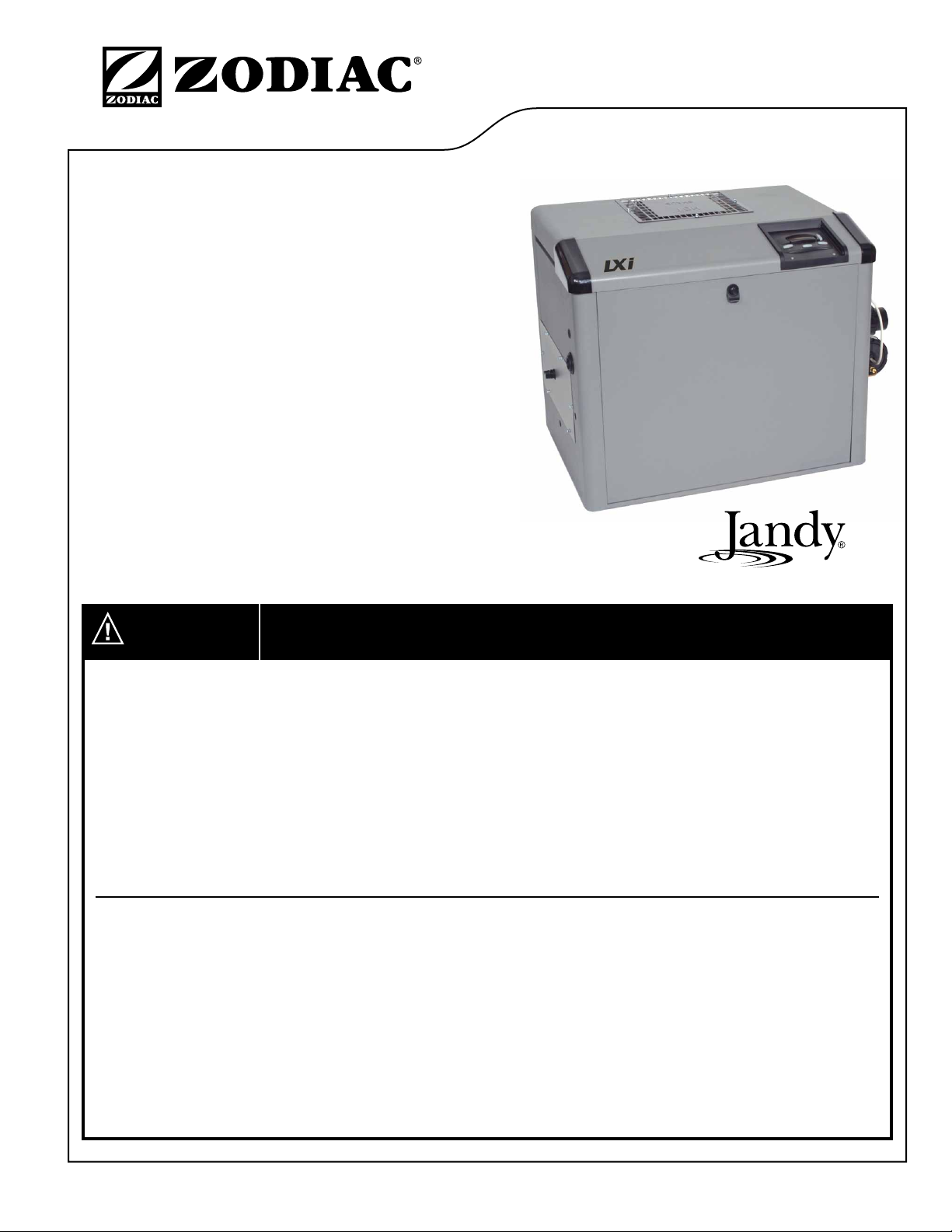
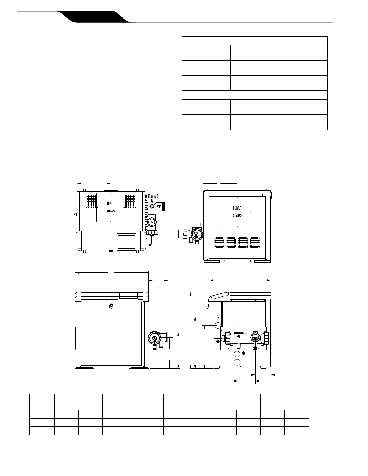
Page 6 ENGLISH Jandy® LXi™ Model Pool and Spa Heater by Zodiac® | Installation and Operation Manual
include dizziness, fainting, drowsiness, lethargy, and
an increase in the internal body temperature. The ef-
fects of hyperthermia include:
• Lack of awareness of impending hazard
• Failure to perceive heat
• Failure to recognize need to leave spa
• Physical inability to leave spa
• Fetal damage in pregnant women
• Unconsciousness resulting in a danger of
drowning
1.2.2 Swimming Pool Energy Saving
Tips
Zodiac Pool Systems, Inc., offers the following
recommendations to help conserve fuel and minimize
the cost of operating your pool heater without sacri-
cing comfort.
1. The American Red Cross recommends a maxi-
mum water temperature of 78°F (25°C). Use an
accurate pool thermometer. A difference of 4F°
(2°C), between 78°F and 82°F (26°C and 28°C),
will use as much as 40% more gas.
2. Carefully monitor the water temperature of your
pool in the summertime. You can reduce heater
usage due to warmer air temperatures.
3. Find the proper setting on the pool heater tem-
perature control and use the Set Point Lockout
feature to discourage further adjustments.
4. Set the pump time clock to start the pump no ear-
lier than 6:00 AM during the pool heating season.
This is the time when nightly heat loss balances.
5. If the pool is only going to be used on weekends,
reduce the heater temperature control setting by
8 or 10 degrees during the week. Reset it to the
78°F (25°C) level a day or so before you plan to
use the pool.
6. During the winter or when on vacation for longer
than a week, shut down the heater by following
the shutdown instructions found on the inside of
the heater.
7. Where possible, shelter the pool from prevailing
winds with well-trimmed hedges or other land-
scaping, cabanas, or fencing.
8. Always use a pool cover when practical. Besides
providing a valuable safety feature, a pool cover
will reduce heat loss, conserve chemicals, and
reduce the load on lter systems.
1.3 Warranty
The LXi heater is sold with a limited factory war-
ranty. Details are included with this heater.
Make all warranty claims to a Zodiac dealer or
directly to the factory. Claims must include the heater
serial number and model (this information can be
found on the rating plate), installation date, and name
of the installer. Shipping costs are not included in the
warranty coverage.
The warranty does NOT cover damage caused
by improper assembly, installation, operation or eld
modication. Also, damage to the heat exchanger by
corrosive water is NOT covered by the warranty. See
Section 8.1, Water Chemistry, for maintaining proper
pool water chemistry.
NOTE Keepthismanualinasafeplaceforfuture
referencewheninspectingorservicingtheheater.
1.4 Codes and Standards
The LXi pool and spa heaters are design-certied
by CSA (Canadian Standards Association) as com-
plying with the latest edition of the Standard for Gas
Fired Pool Heaters, ANSI Z21.56 in the USA and
CAN-4.7 in Canada.
All Zodiac heaters must be installed in accor-
dance with the local building and installation codes as
per the utility or authorities having jurisdiction.
In the absence of local codes, refer to the latest
edition of the following national codes for installation:
1. In the United States, the National Fuel Gas
Code®, NFPA 54/ANSI Z223.1. Pay particular
attention to the chapter addressing Venting of
Equipment.
2. In Canada, the Natural Gas and Propane Instal-
lation Code, CAN/CSA-B149.1. However, for
minimum combustion air requirements, table
3 of this manual MUST be followed for proper
and safe operation. The Jandy LXi heater may
not operate properly when installed with the only
the minimum combustion air openings allowed in
CAN/CSA-B149.1.
The LXi pool and spa heaters meet or exceed the
requirements of energy conservation regulations, such
as those in California, Hawaii, New York, Oregon and
other states that require that a pool heater have inter-
mittent ignition. In addition, the natural gas models
of this heater comply with the California South Coast
Air Quality Management District's (SCAQMD) Rule
1146.2 for Nitrogen Oxide (NOx) emissions.
Any changes to the heater, gas controls, gas
orices, wiring, draft diverter, or improper installation
may void the warranty. If change is required to any of
the above, consult the factory.

Page 7
ENGLISH
Installation and Operation Manual | Jandy® LXi™ Model Pool and Spa Heater by Zodiac®
1.5 Technical Assistance
Consult Zodiac Pool Systems, Inc. or your local
Zodiac distributor with any questions or problems
involving the specications, installation, and operation
of your Zodiac equipment. An experienced member of
the technical support staff is ready to assist you in as-
suring the proper performance and application of
Zodiac products. For technical support, call the Tech-
nical Support Department at 800.822.7933.
1.6 Materials Installer Must Provide
1.6.1 Materials for All Applications
The following items are needed and are to be
supplied by the installer for all LXi heater
installations:
1. The correct size gas pipe to supply gas from the
meter to the heater. See Section 4.1.
2. A manually operated gas valve to be installed in
the gas line outside of the heater jacket.
3. A suitable gas union joint to connect the heater to
the gas line outside of the heater.
4. Plumbing items needed to provide a sediment
trap (drip leg) in the gas line between the manual
gas valve and the heater. See Section 4.1.
5. A 120V AC or 240V AC power supply. A junc-
tion box is not needed at the heater; connections
are made inside of the heater jacket.
1.6.2 Materials for Special
Applications
In addition to the items listed above, the follow-
ing items are needed for special applications:
1. A factory authorized vent collar and any vent
pipe needed for indoor installations in the USA
and outdoor shelter installations in Canada, see
Section 3.3.2. A vertical vent collar comes with
the unit. A side vent kit is available from your
Zodiac distributor.
2. Primer and cement suitable for cementing CPVC
pipe to PVC pipe and an appropriate coupling
for connecting the factory supplied CPVC pipe
nipples to PVC pool plumbing.
3. A noncombustible platform for installation on
combustible surfaces, See Section 2.3.3. Non-
combustible bases are available from your Zodiac
distributor.
1.7 Specications
1.7.1 General Specications
1. Installation Location:
Certied for use:
In the USA:
Natural Gas: Indoor and Outdoor
LP: Indoor and Outdoor
In Canada:
Natural Gas : Outdoor and Outdoor
Shelter
LP: Outdoor and Outdoor
Shelter
2. Minimum Clearance From Combustible
Material:
See Table 2 in Section 2.3.2.
3. *Gas Pipe/Heater Gas Valve Connection:
Natural Gas: 3/4" NPT
LP: 3/4" NPT
*For diameter of gas line from meter to heater, see Table 5 in
Section 4.1.
4. Supply Gas Type:
Certied for use with:
Natural Gas and LP
5. Inlet Gas Supply Pressure:
Minimum Maximum
Natural Gas: 5.0 "WC 10.5 "WC
LP: 11.0 "WC 14.0 "WC
6. Manifold Gas Pressure:
Natural Gas: 2.5 "WC
LP: 9.0 "WC
7. Air Plenum Pressure: 1.5 "WC
8. Burner Throat Pressure: 1.0 "WC
9. Water Pipe/Heater Connection:
*2" Unthreaded PVC or CPVC
*Other size pipes may be used. See Section 5.5 for details
10. Water Flow Rate:
Maximum: 125 gpm (475 lpm)
Minimum: 30 gpm (110 lpm)
11. Working Water Pressure:
Maximum: 75 psi
12. Exhaust Vent Connection Size (Category I):
Model:
250 6" Diameter
400 8" Diameter
13. Electrical Supply:
Either 120 Volts AC or 240 Volts AC.

Page 8 ENGLISH Jandy® LXi™ Model Pool and Spa Heater by Zodiac® | Installation and Operation Manual
Model
HeaterWidth
Dim"A" HeaterSidetoMid-Vent VentDiameter
(CategoryI) FiringRate HeaterVent
LocationDim"B"
in. cm in. cm in. cm BTU/HR kcal in. cm
250 23.5 59.7 10.5 26.7 6 15.2 250,000 63 10.5 26.7
400 32.0 81.3 15.6 39.7 8 20.3 399,000 101 15.6 39.6
14. Modication of Heater for High Altitude:
LXi heaters are normally shipped from the fac-
tory in the low altitude (sea level) operational
conguration. Table 1 denes the altitude des-
ignations as described by the Standard for Gas
Fired Pool Heaters, ANSI Z21.56 in the United
States and Gas-Fired Appliances For Use At
High Altitudes, CAN1-2.17 in Canada. When
an LXi heater is to be installed in a high altitude
application, the burner throat pressure will need
to be adjusted to achieve 1.0"WC. See Section
10.4.3 for instructions on how to do this.
1.7.2 Dimensions
See Figure 1 for a diagram showing the heater's
exterior dimensions and dimensions to critical connec-
tions on the heater.
Figure 1. General Configuration
A
6.9”
(17.5 cm)
11.2”
(28.4 cm)
13.1”
(33.3 cm)
27.5”
(69.9 cm)
18.5”
(47 cm)
15.5”
(39.4 cm)
22.3”
(56.6 cm)
5.5”
(14 cm)
6.0”
(15.2 cm)
BB
Table 1. Altitude Designations For The LXi Heater
NATURALGAS
ALTITUDE
DESIGNATION
UNITED
STATES CANADA
LOW
ALTITUDE
0-4500FT 0-4500FT
(0-1370M)
HIGH
ALTITUDE
4501-10,000FT NOT
APPLICABLE
LP
LOW
ALTITUDE
0-4500FT 0-4500FT
(0-1370M)
HIGH
ALTITUDE
4501-10,000FT NOT
APPLICABLE

Page 9
ENGLISH
Installation and Operation Manual | Jandy® LXi™ Model Pool and Spa Heater by Zodiac®
Section 2. Installation Instructions
2.1 Introduction
WARNING
Improperinstallationormaintenancecancause
nauseaorasphyxiationfromcarbonmonoxidein
uegaseswhichcouldresultinsevereinjury,or
death.Forindoorinstallations,asanadditional
measureofsafety,ZodiacPoolSystems,Inc.
stronglyrecommendsinstallationofsuitableCarbon
Monoxidedetectorsinthevicinityofthisappliance
andinanyadjacentoccupiedspaces.
AVERTISSEMENT
Uneinstallationouunentretieninadéquatpeut
causerlanauséeoul’asphyxieenraisondu
monoxydedecarboneprésentdanslesgazde
combustionetmêmeentraînerdesblessures
gravesoulamort.Pourlesinstallationsintéri-
eures,commemesuredesécuritéadditionnelle,
ZodiacPoolSystems,Inc.recommandefortement
l’installationdedétecteursdemonoxydedecarbone
prèsdecetappareilainsiquedanslesespaces
adjacentsoccupés.
Install the LXi heater and vent collar in accor-
dance with the procedures in this manual, local codes
and ordinances, and in accordance with the latest edi-
tion of the appropriate national code. See Section 1.4,
Codes and Standards.
All gas-red products require correct installation
to assure safe operation. The requirements for pool
heaters include the following:
1. Field assembly (if required)
2. Appropriate site location (clearances) and ooring
3. Sufcient combustion and ventilation air
4. Properly sized gas meter and piping
5. Proper electrical wiring (if required)
6. Adequate water ow
This manual provides the information needed to
meet these requirements. Review all application and
installation procedures completely before continuing
the installation.
2.2 Field Assembly
The LXi heater can be installed in a variety of
ways, some of them requiring preparation or assembly
in the eld. The heater is shipped from the factory
with an exhaust vent congured for an outdoor instal-
lation. The LXi heater is also design certied for “In-
door” installations in the United States and “Outdoor
Shelter” installations in Canada when equipped with a
vent collar and the appropriately sized exhaust vent.
Check the rating plate on the heater or the Parts
List (Section 11.2) in this manual for the correct
Zodiac vent collar part number. For specic installa-
tion information see Section 2.3.5, Indoor and Outdoor
Shelter Installations.
Water connections are provided on the right side
of the heater but can be changed to the left side by
reversal of the heat exchanger. It is best to handle these
preparations before the heater is installed in its nal lo-
cation. See Section 5.4, Reversible Water Connections,
in this manual for instructions.
2.3 Location Requirements
2.3.1 Introduction
CAUTION
Whenpoolequipmentislocatedbelowthepoolsur-
face,aleakfromanycomponentcancauselarge
scalewaterlossorooding.ZodiacPoolSystems,
Inc.,cannotberesponsibleforsuchwaterlossor
oodingorresultingdamage.
ATTENTION
Lorsquel’équipementd’unepiscineestsituésous
lasurfacedel’eau,unefuiteprovenantden’importe
quelélémentpeutcauseruneperted’eauimportante
ouuneinondation.ZodiacPoolSystems,Inc. n’est
pasresponsabledespertesd’eau,desinondations
oudesavariescauséesparuneinstallationouun
entretieninadéquat.
The LXi heater may be installed indoors or
outdoors, as outlined in later sections. Location of
the heater below or above the pool water level affects
operation of its water pressure switch. See sections on
water piping and heater start-up for more information
about this.
Avoid placing the heater in locations where it can
cause damage by water or condensate leakage. If this
is not possible, provide a suitable drain pan to catch
and divert any leakage. The pan must not restrict the
air ow around the heater.
All criteria given in the following sections reect
minimum clearances as stated in the national stan-
dards. However, each installation must also be evaluat-
ed, taking into account the prevailing local conditions
such as wind speed and direction, proximity and height
of walls that may block ventilation, and proximity to
public access areas.
2.3.2 Clearances
The heater must be placed to provide clearances
on all sides for maintenance and inspection. There
must also be minimum distances maintained from
combustible surfaces. See Table 2.
At least 18 inches (457mm) access must be
available in front of the heater for burner removal and
access to the igniter.

Page 10 ENGLISH Jandy® LXi™ Model Pool and Spa Heater by Zodiac® | Installation and Operation Manual
If the heater is to be installed in a garage, or sim-
ilar structure, all burners and burner ignition devices
must have a minimum 18 inches (457mm) clearance
above the oor.
This heater must be installed at least 5 feet
(1.52m) from the inside wall of a pool unless the
heater is separated from the pool by a solid fence, wall
or other permanent solid barrier.
Ce chauffe-piscine doit être installé au moins 5
pieds (1.52m) de la paroi interne de la piscine à moins
d'être isolé de la piscine par une clôture, un mur ou
autre barrière permanente.
2.3.3 Flooring
The heater must be installed on a level surface
of noncombustible construction or on re-resistant
slabs or arches. Noncombustible ooring is dened
as ooring material and surface nish not capable of
being ignited and burning and with no combustible
materials against the underside. Acceptable materials
are those consisting entirely of a combination of steel,
iron, brick, tile, concrete, slate, glass or plaster. Do not
install the heater directly on a combustible wood or
carpet oor without placing a noncombustible platform
between the oor and the heater.
The heater can be installed on a combustible
oor if a noncombustible base assembly, available
from Zodiac Pool Systems, Inc., is used. See the heater
rating plate or the Parts List (Section 11) in this manual
for the appropriate base part number. Heaters must
never be installed directly on carpeting.
As an alternative to the Zodiac noncombustible
base plate, in the United States, the National Fuel Gas
Code® (NFPA 54 / ANSI Z223.1), and in Canada, the
Natural Gas and Propane Installation Code (CAN/
CSA-B149.1), allow a heater to be placed on a com-
bustible surface when there is a platform under the
heater made of hollow masonry no less than four (4)
inches (102 millimeters [mm]) thick, covered with
sheet metal at least 24 gauge thick and extending be-
yond the full width and depth of the heater by at least
six (6) inches (153 mm) in all directions. The masonry
must be laid with ends unsealed, and joints matched to
provide free circulation of air from side to side through
the masonry, see Figure 2. If the heater is installed in a
carpeted alcove, the entire oor of the alcove must be
covered by a noncombustible panel.
2.3.4 Outdoor Installation
The LXi heater can be installed in the outdoor
conguration as received from the factory.
Locate the heater in an open, unroofed area. Do
not install the heater under a deck. Do not locate the
heater below or adjacent to any doors, glass openings,
louvers, grills, etc., which connect in any way with an
inhabited area of a building, even though the access
might be through another structure (e.g., a garage or
utility room). In the United States the vent system shall
terminate at least four (4) ft (1.2 m) below, four (4) ft
Table 2. Minimum Heater Clearances From Combustible Surfaces
NOTE ClearanceslistedinTable2are
manufacturer'stestedvalues.
Thesearegivenasminimum
values.Wherelocalandnational
codesapply,andvaluesare
differentthanthoselistedin
Table2,usethegreatervalueto
ensuresafeoperation.
* In Canada - 24 in (61cm)
6”
(15 cm)
6”
(15 cm)
Figure 2. Noncombustible Platform
Notes:
1. Blocksmustprovideasolidbaseandbebracedsothey
cannotslipoutofplace.
2. Airopeningsinblocksmustbearrangedtoprovideunre-
strictedopeningthroughentirewidthorlengthofbase.
3.Sheetmetalmustbeatleast24ga.andextend6"beyond
theheaterjacketonallsides.
SIDE OF
HEATER
INDOOR (OUTDOOR
SHELTER) INSTALLATION OUTDOOR INSTALLTION
INCHES CENTIMETERS INCHES CENTIMETERS
BLANK 8 20.3 8 20.3
REAR 4 10.2 4 10.2
PIPING 16 40.6 16 40.6
TOP 36 99.0 OPENUNROOFEDAREA
FRONT 18* 45.7* 18* 45.7*

Page 11
ENGLISH
Installation and Operation Manual | Jandy® LXi™ Model Pool and Spa Heater by Zodiac®
(1.2 m) horizontally from, or 1 ft (300 mm) above any
door, operable window, or gravity inlet into any build-
ing. In Canada, the heater must be installed so that the
exhaust point of the heater is at least 10 feet (3.0 m)
from any building opening. See Figure 3.
WARNING
United States
Donotinstalltheheaterwiththetopofthevent
assemblywithin4feet(1.22m)horizontally,4feet
(1.22m)beloworlessthan1ft(300mm)aboveof
anyopeningintoabuilding.
Canada
Donotinstalltheheaterwiththetopoftheventas-
semblywithin10feet(3.05m)ofanyopeningintoa
building.
AVERTISSEMENT
Lorsquevousinstallezl’appareildechauffage,
assurez-vousquel’ouvertured’aérationsetrouveà
unminimumde10pieds(3.05m)detouteouver-
tured’unbâtiment.
The top surface of the heater must be at least 3
feet (0.9 m) above any forced air inlet, or intake ducts
located within 10 (3.0 m) feet horizontally.
If the heater is installed under an overhang, there
must be a minimum clearance of 5 feet (1.5 m) above
the top of the heater and the structure should not over-
hang the heater more than 12 inches (0.30 m). The area
under the overhang must be open on three (3) sides.
This prevents combustion gases from being diverted
into living areas through doors, windows, or gravity
inlets.
Ne pas installer ce chauffe-piscine sous une
saillie mesurant moins de 3 pi de hauteur. La partie
sous la saillie doit être ouverte sur 3 côtés.
Figure 3. Outdoor Heater Installation
If the heater is installed close to a structure, pro-
tect it from rain water runoff with rain gutters on the
roof or other measures. Do not locate the heater near
irrigation sprinkler systems that could spray water on
it. Water from sprinklers may cause damage to controls
and electronic components.
In Florida, it is required that the heater be secure-
ly fastened to the equipment pad. Use a size
1/4" x 2-1/4" long galvanized or plated concrete
screws and washers at each of the four (4) tabs located
at the base of the heater. Mounting the appliance in
this manner meets the applicable requirements of the
Florida Building Code.
Mounting screws are not provided with this
heater. After placing the heater on the equipment pad,
drill a hole in the concrete at each of the four (4) tabs
on the feet of the heater. (The correct size drill bit is
usually provided with the concrete screws when pur-
chased). Place a screw in each of the holes and fasten
the heater to the equipment pad, see Figure 4. Do not
over-torque the screws. Other jurisdictions may have
similar requirements. Please check your local codes for
relevant details.
1/4” X 2-1/4”
GALVANIZED OR PLATED
CONCRETE SCREWS
Figure 4. Anchor Heater To Equipment Pad
2.3.5 Indoor and Outdoor Shelter
Installations
An outdoor shelter (Canada only) is an unoccu-
pied enclosure which does not communicate directly
with occupied areas. All indoor installations and
outdoor shelter installations require a factory approved
vent collar. The vent collar must be installed without
modication and in accordance with the instructions
provided by the manufacturer. For sidewall venting, a
side vent kit is available from your Zodiac distributor.

Page 12 ENGLISH Jandy® LXi™ Model Pool and Spa Heater by Zodiac® | Installation and Operation Manual
Une remise extérieure (au Canada seule-
ment) est un endroit inoccupé qui ne communique
pas directement avec les endroits occupés. Toutes
les installations intérieures et remises extérieures
exigent l’addition d’une cheminée approuvée par le
manufacturier. La cheminée doit être installée sans
aucune modication et selon les exigences fournies
par le manufacturier.
The applicable codes, standards and Zodiac
Pool Systems, Inc., require that the heater be properly
vented as outlined in this manual. Proper ventilation
of exhaust and combustion air are essential for the safe
and efcient operation of the heater. See Section 3.
2.3.5.1 Converting the Grill to a Vent
Collar
If the LXi heater is to be installed either indoors
or in an outdoor shelter, its exhaust discharge grill
must be removed. The LXi heater comes with the
vertical vent collar factory installed. The optional side
vent plate, gasket and screws can be ordered as a parts
kit, see the parts list in Section 11 of this manual. The
conversion can be done quite simply as follows:
1. Remove the vent exhaust grill by removing the
four screws which retain it. The grill and the
screws may be discarded. See Figure 5.
2. Install the vent pipe on the indoor vent collar.
The collar will accommodate vent piping of nom-
inal 6”, 7” or 8” diameter, see Table 4, depending
upon the model of your heater. See vent installa-
tion section for important information on select-
ing proper pipe size. See Figure 6.
Section 3. Venting
3.1 Combustion Air Supply
The heater location must provide sufcient air
supply for proper combustion and ventilation of the
surrounding area as outlined in the latest edition of
ANSI standard Z223.1 (NFPA® 54). The minimum
allowable combustion air opening in the Canadian
Natural Gas and Propane Installation Code (CAN/CSA
B149.1) are not sufcient for safe and proper operation
of the LXi heaters. Combustion air openings must be
followed per the requirements of ANSI Z223.1 (NFPA
54) and Table 3.
In general, these requirements specify that the
room in which a heater is installed should be provided
with two (2) permanent air supply openings; one (1)
within 12 inches (305 mm) of the ceiling, the other
within 12 inches (305 mm) of the oor. All indoor
installations must have openings to outside air for
combustion, ventilation, and dilution of ue gases
from inside the building. See Figure 7 and Table 3.
Zodiac Pool Systems, Inc., does not recommend
indoor installations that do not provide combustion air
from outside the building.
All outdoor shelter installations (Canada only)
must have uninterrupted openings to outside air for
combustion and ventilation. The installation must
be in accordance with the latest edition of CAN/
CSA B149.1. For combustion air supply openings,
however, the requirements of Table 3 MUST be fol-
lowed for safe and proper operation. The minimum
combustion air openings allowed in CAN/CSA B149.1
are NOT sufcient for the LXi heaters.
Zodiac Pool Systems, Inc., does not recommend
outdoor shelter installations that depend on internal air
for combustion. Combustion air should be ducted to
the heater from outside the structure.
Outside Air Supply: When combustion air is
supplied directly through an outside wall, each open-
ing should have a minimum free area of 1 square inch
per 4,000 BTU/h (1.2kW) input of the total input rat-
ing of all appliances in the enclosed area.
If air is provided through horizontal ducts, each
opening and duct must provide 1 square inch of ow
area for each 2000 BTU/h (0.6 kW). These require-
ments are summarized in Table 3. Note that the areas
specied are net free areas and should be increased
when the openings are covered by screens, louvers,
grills or other protective covers. See Figure 8 and
Table 3 notes.
Figure 6. Vent Pipe Installation
Figure 5. Removal of Outdoor Exhaust Grill
OUTDOOR
VENTCOVER
VERTICAL
VENTCOLLAR

Page 13
ENGLISH
Installation and Operation Manual | Jandy® LXi™ Model Pool and Spa Heater by Zodiac®
The heater must be completely isolated and
protected from any source of corrosive chemical fumes
such as those emitted by trichlorethylene, perchloro-
ethylene, chlorine, etc.
WARNING
Donotstoreanychemicals,cleaners,orothercor-
rosivematerialnearcombustionairopeningsorin
theroom.Avoidlocatingapplianceventsinthevi-
cinityofcombustionairopenings.Failuretoprevent
corrosivematerialsfrommixingwithcombustionair
canresultinreducedheaterlifeandunsafeheater
operation.
AVERTISSEMENT
Nepasentreposerniutiliserd'essencenid'autres
vapeursouliquidesinammablesàproximitédecet
appareiloudetoutautreappareil.
3.2 Exhaust Venting
When converted to indoor and outdoor shelter
venting conguration, the LXi heater has a vent collar
tting for attachment to the venting for Category I
vertical venting. The diameter of the vent collar and,
thus, the minimum diameter of the vent pipe to be used
is determined by the model of heater installed and the
type of venting. The only correct procedure for vent
pipe sizing is to do so in accordance with Table 4
and the applicable installation code as stated in the
following "Warning" warning. Note that with hori-
zontal Category III type vent installations, the venting
may be smaller than the vent collar for Category I
vertical venting. See Table 4. Category III vent collars
are available separately.
Table 3. Air Openings to Outside
NOTE Exceptforthecombustionairopenings
requirements,inCanada,followCanadian
Standard,CAN/CSA-B149.1orlocalcodes.
FollowtherequirementsofTable3forthe
minimumcombustionairopeningsrequired.
Exhaust Fans or Vents: Any equipment
which exhausts air from the room where the heater
is installed can deplete the combustion air supply or
reverse the natural draft action of the venting system.
This could cause ue products to accumulate in the
room. Additional air must be supplied to compensate
for such exhaust.
The information in Table 3 is not applicable in
installations where exhaust fans or blowers of any type
are used. Such installations must be designed by quali-
ed engineers.
3)
Notes:
1. Useapproved
roofjack.
Figure 7. Indoor Installation Venting (USA), or Outdoor Shelter (Canada)
RequiredNetFreeOpenArea*
forCombustionAirOpenings
*Areaindicatedisforone(1)oftwo(2)openings;one(1)at
oorlevelandone(1)attheceiling,sothetotalnetfreearea
wouldbedoubletheguresindicated.Forspecialconditions,
refertoNFPA54ANSIZ223.1.
The requirements in this table for combustion air openings
MUST be followed for all Canadian installations also. The
minimumallowablecombustionairopeningsintheCanadianNa-
tionalStandardsCAN/CSAB149.1arenotadequateforproper
operationoftheLXiheaters.
NOTE: If using screens and/or metal louvers, compensate by adding
50% additional area to each opening. If using wood louvers each
opening must be at least four (4) times the area indicated in the table
above.
Model Directfromoutside Ductfromoutside
in2(cm2) in2(cm2)
250 63 (406) 126 (813)
400 100 (645) 200 (1290)

Page 14 ENGLISH Jandy® LXi™ Model Pool and Spa Heater by Zodiac® | Installation and Operation Manual
WARNING
VentpipediametermustbeasrequiredbytheNa-
tionalfuelGasCodeZ223.1ortheCanadianInstal-
lationCodesforGasAppliancesCAN/CSA-B149.1.
Undersizedpipecanresultininadequateventing
andoversizepipecanresultinventcondensation.
Ineithercasetheresultcanbereleaseofcombus-
tionproductstotheindoors.Thiscancauseserious
injuryordeathbycarbonmonoxidepoisoningor
asphyxiation.
AVERTISSEMENT
Lediamètredestuyauxdeventilationdoitrépondre
auxexigencesduNational Fuel Gas Code Z223.1
ouducodecanadiendesinstallationsdesappar-
eilsàgazCAN/CSAB149.1.Destuyauxtroppetits
risquentd’entraîneruneventilationinadéquateet
destuyauxtropgrosrisquentdeprovoquerune
condensationdanslestuyaux.Dansuncascomme
dansl’autre,desproduitsdecombustionrisquent
des’échapperdanslebâtimentetcauserdesbles-
suresgravesoul’asphyxieparlemonoxydede
carbone.
3.3 Vent Pipe Sizing and General
Installation
The LXi may be installed with venting as a Cat-
egory I or III Fan-Assisted appliance or outdoors with
the integral vent grill.
3.3.1 Outdoor Installations
For outdoor installations, exhaust venting con-
siderations will determine the placement of the heater,
see Section 2.3.4. If the heater cannot be placed so
as to meet the requirements stated in Section 2.3.4,
a vent collar may be added to the heater to move the
exhaust vent opening to a position that complies with
the requirements. In all cases, vent collars must be of
the same diameter as the exhaust outlet of the heater.
Approved vent collars may be obtained through your
Zodiac distributor.
3.3.2 Indoor and Outdoor Shelter
Installations
All indoor installations and outdoor shelter
installations require a factory approved vent collar.
The vent collar must be installed without modication
and the Category I vertical vent collar comes factory
installed.
All vent installations must be made in accordance
with all local, state or provincial codes and with:
1. The National Fuel Gas Code, ANSI Z223.1
(NFPA 54), latest edition; pay particular attention
to the chapter addressing “Venting of Equip-
ment.” Applicable provisions of additional ap-
plicable local building codes may also need to be
followed.
2. In Canada, CAN/CSA B149.1.
In all installations, avoid terminating heater vents
near air conditioning or air supply fans. The fans can
pick up exhaust ue products from the heater and
return them inside the building, creating a possible
health hazard.
Do not locate the vent terminal where ue prod-
ucts could strike against building materials and cause
degradation.
Vent opening should be well away from trees
or other obstructions that would prevent free air ow
to and from vent terminal. Do not terminate the vent
under decks, stairways, or car ports.
The LXi may be installed for use with standard
Category I venting per tables provided in most local
codes for Category I Fan-Assisted appliances. If the
local code does not include such tables, refer to the
National Fuel Gas Code NFPA 54 / ANSI Z223.1 or
the Canadian Natural Gas and Propane Installation
Code, CAN/CSA-B149.1. Note that the tables for
fan-assisted appliances include both maximum and
minimum vent loading gures. The primary purpose of
the maximum ratings are to assure that the vent oper-
ates with negative pressure throughout its length. The
minimum ratings are to assure that vent gases do not
cool too much and thereby assure that condensation
does not occur.
When the installation requires horizontal venting
in excess of what is allowed for Category I installa-
tions or calls for horizontal discharge, the LXi may be
installed with a Category III venting system. Category
III applications must be installed per this installa-
tion manual and the vent manufacturer's installation
instructions. The venting materials must comply with
UL 1738 for Category III venting systems and be con-
structed of stainless steel. In Canada, the venting ma-
terials must be ULC S636 compliant. Vent piping must
be adequately supported with no low spots or sagging
that will allow condensate to collect. The heater must
not be used to support the vent pipe. Horizontal runs
must be sloped upwards away from the heater to a
vent terminal at a minimum of 1/4 inch per horizontal
Table 4. Vent Pipe Sizing Table
Heater
Size
CategoryI CategoryIII
VentPipeDiameter
MinimumVertical
VentPipeDiameter
(RefertoNFPA®
54orlocalcodes)
VentPipeDiameter
Maximum
HorizontalVent
Length
Maximum
No.of
Elbows
CategoryIII
Sidewall
VentKit
CategoryIII
Vertical
VentKit
250 6in 15cm 6in 15cm 5in 13cm 25ft 7.6m 3 R0467301 R0484301
400 8in 20cm 8in 20cm 6in 15cm 25ft 7.6m 3 R0467303 R0484303

Page 15
ENGLISH
Installation and Operation Manual | Jandy® LXi™ Model Pool and Spa Heater by Zodiac®
NOTE Forapprovedsidewallventkitsandspecic
installationinstructions,seeSection 11,
Replacement Parts.
Zodiac Pool Systems, Inc. does not recommend
using a "Common Vent" to vent multiple appliances
through a common duct. However, if no other option is
deemed available by the installer, each appliance must
have its own vent temperature limit switch. All vent
limit switches must be wired in series so as to prevent
any appliance from ring in the event of a blocked
vent. Refer to ANSI Z223.1 or, in Canada, to CAN/
CSA B149.1 for more information on multiple venting.
Do not connect vent systems of different categories
to the same venting system. Seek the assistance of a
Registered Professional Engineer for proper design of
a common venting system.
3.3.3 Inspection and Replacement of
Existing Vent System with New
Components
If the LXi is being installed to replace an existing
pool heater, it is recommended that a new appropriate
venting system be installed with the new heater. How-
ever, if an existing venting system must be used, be
sure to carefully inspect the venting system to ensure
that it is in good condition and continues to be appro-
priate for the LXi heater. Replace any parts that are
not in good and serviceable condition with new parts
before completing the pool heater installation.
foot (2 cm/m). The LXi is designed for Category III
venting with a maximum of 25 ft (7.6 m) of vent pipe
and up to three (3) elbows. For each additional elbow,
reduce the maximum vent pipe length by 10 ft (3 m).
See Table 4 for the minimum vent diameter for the
model size to be installed.
Side wall vents must be installed and located in
accordance with the National Fuel Gas Code® NFPA
54 / ANSI Z223.1 or the Canadian Natural Gas and
Propane Installation Code CAN/CSA-B149.1. See
Figure 8 Side Wall Vent Terminations.
IMPORTANT NOTEIntheCommonwealthof
Massachusetts,additionalrequirements,
coveredindocumentCMR2485.00,which
supersedesomeoftherequirementsof
ANSIZ223.1(NFPA54)applytoSideWall
HorizontallyVentedappliances.Ifinstalling
thisproductusinganapprovedside-wall
horizontalventsystemintheCommonwealth
ofMassachusetts,besuretoadheretothese
additionalrequirements.Theserequirements
includeverbiagethatsaysthattheproperty
owneristoensurethatCarbonMonoxide
Detectorsareinstalledinthevicinityof
theapplianceandalsoonalllevelsofthe
dwellinginwhichtheapplianceisinstalled.
Forfurtherinstructions,contactZodiacPool
Systems,Inc.,TechnicalSupportDepartment
at800.822.7933.
Figure 8. Side Wall Vent Terminals

Page 16 ENGLISH Jandy® LXi™ Model Pool and Spa Heater by Zodiac® | Installation and Operation Manual
Section 4. Gas Connections
4.1 Gas Supply and Piping
Review the following general instructions before
continuing the installation.
WARNING
TheLXipoolandspaheatersaredesignedforuse
witheithernaturalgasorLPgas.Checktherating
plateontheinnerpaneltobesurethattheheateris
designedtousethetypeofgasbeingsupplied.DO
NOT ATTEMPT TO CONVERT THIS HEATER FOR
USE WITH ANY OTHER TYPE OF FUEL.
AVERTISSEMENT
Lesappareilsdechauffageàfaiblesémissions
LXipourpiscinesetcuvesthermalessontconçus
pourêtreutilisésavecdugaznatureloudugazde
pétroleliquéé(GPL).Vériezl’informationinscrite
surlaplaquesignalétiquedupanneauintérieurpour
vousassurerquel’appareilestconçupourletype
degazfourni.NE PAS ESSAYER DE CONVERTIR
CET APPAREIL À UN AUTRE TYPE DE GAZ.
1. Gas piping installation must be in accordance
with the latest edition of ANSI Z223.1 and all
local codes. In Canada, the installation must be in
accordance with CAN/CSA B149.1 and all local
codes that apply.
2. Check the gas supply to be sure that it is the same
as the gas indicated on the heater's rating plate.
LXi heaters, as shipped from the factory, are set
to operate within the low altitude range. Follow
the instructions in Section 10.4.3 to adjust the
heater for high altitude.
CAUTION
Permanentdamagetothegasvalvewilloccurifthe
followingproceduresarenotfollowed.
ATTENTION
Vousendommagerezlasoupapedegazsivousne
respectezpaslesprocéduressuivantes.
3. Use the gures in Table 5 to size the gas inlet
piping from the gas meter to the heater. Check all
local codes for compliance before installing the
heater.
DistancefromGasMeter
Heater
Size
0-50feet
(0-15m)
50-100feet
(15-30m)
100-200feet
(30-60m)
in. mm in. mm in. mm
250 1 25 1-1/4 32 1-1/4 32
400 1-1/4 32 1-1/2 38 1-1/2 38
Notes:
*1.Thesenumbersarefornaturalgas (0.65Sp. Gr.) and
arebasedon1/2inch(3.45kPa)watercolumnpressure
drop.Checksupplypressurewithamanometer,andlocal
coderequirementsforvariations. For LP gas, reduce
pipe diameter by one size, but maintain a minimum
3/4 inch diameter.
2. Checksupplypressureandlocalcoderequirementsbefore
proceedingwithwork.
3. Pipettingsmustbeconsideredwhendetermininggas
pipesizing.
4. Install a sediment trap (drip leg) ahead of the gas
controls, as shown in Figure 9. Fit the trap with a
threaded cap which can be removed for cleaning.
5. Install a manual gas shutoff valve for service
and safety. Do not use a restrictive gas cock.
DO NOT USE FLEXIBLE GAS PIPING, it will
restrict the gas ow to the heater.
6. Disconnect the heater and its individual shutoff
valve from the gas supply system during pressure
testing of the system at pressures higher than 1/2
pounds per square inch (psi) (3.45 kilopascals
[kPa]). If the test pressure is equal to or less than
1/2 psi (3.45 kPa), close the manual shutoff valve
on the heater during the piping pressure test.
7. If the gas supply pressure is less than required,
check for undersized pipe between the meter and
the heater, a restrictive tting, or an undersized
gas meter. Gas supply pressures to the heater are
listed in Table 6.
Figure 9. Proper Design for a Sediment Trap/Drip Leg
APPROVED
Table 5. Supply Gas Pipe Size Requirements*

Page 17
ENGLISH
Installation and Operation Manual | Jandy® LXi™ Model Pool and Spa Heater by Zodiac®
SupplyPressure Minimum Maximum
NaturalGas 5.0inchesW.C.
(1.2kPa)
10.5inchesW.C.
(2.6kPa)
LPGas 11.0inchesW.C.
(2.5kPa)
14.0inchesW.C.
(3.5kPa)
ManifoldPressure Nominal
NaturalGas 2.5inchesW.C.(0.6kPa)
LPGas 9.0inchesW.C.(2.2kPa)
NOTEThemaximuminletgaspressuremustnot
exceedthespeciedvalue.Theminimum
valuelistedisforthepurposeofinput
adjustment.RefertoTable6.
8. To connect the gas supply line to the heater’s gas
valve, make sure the steel elbow (supplied with
the manifold) is screwed into the inlet side of the
gas valve. The heater is designed so that the gas
supply line may enter through either side of the
heater. Tighten the elbow until the desired orien-
tation is achieved.
CAUTION
Donotovertightentheelbow.Overtighteningwill
crackthegasvalve.DonotuseTeon®tapeto
wraptheelbowthreads.
ATTENTION
Neserrezpastroplecoude.Vousrisqueriezdes-
surerlasoupapedegaz.N’entourezpasleletage
descoudesderubanàjoints.
9. Before operating the heater, test the complete gas
supply system and all connections for leaks using
a soap solution. Do not use an open ame.
CAUTION
Someleaktestsolutions(includingsoapandwater)
maycausecorrosionorstresscracking.Rinsethe
pipingwithwateraftertesting.
ATTENTION
Certainessolutionsd’essaid’étanchéité(ycompris
l’eauetlesavon)peuventcauserdelacorrosion
oudelassuration.Rincezlestuyauxàl’eauaprès
l’essaid’étanchéité.
4.2 Manifold Pressure
Conrm that gas supply pressure is correct. If
the gas supply pressure is less than required, check
for undersized pipe between the meter and the heater,
a restrictive tting, or an undersized gas meter. Gas
supply pressures to the heater, when it is operating, are
listed in Table 6.
CAUTION
ManifoldgaspressurefortheLXinaturalgasheat-
ersshouldbesetat2.5" WC.Propaneheaters
shouldbesetto9"WC.
ATTENTION
Lapressionducollecteurdepressionpourles
systèmesdechauffageaugaznatureldevraitêtre
de2.5'’WC.Pourlessytèmesdechauffageaugaz
propanedevraitêtrede9'’WC.
The manifold pressure may be checked by con-
necting a manometer to the pressure port on the outlet
side of the valve. The pressure will be zero when the
heater is not running. When the heater is operating the
manifold gas pressure should be 2.5" WC for natural
gas heaters and 9.0" WC for LP gas heaters.
If the manifold pressure indicated above is not
correct, check the gas train for possible problems.
Check the meter, gas line, gas ttings, and gas shut off
for under sizing. Check the gas valve inlet for excess
pipe dope, if all is correct, then it may be necessary to
adjust the gas valve regulator. To adjust the manifold
gas pressure, rst remove the slotted cap next to the
inlet pressure port on the inlet side of the gas valve.
Under the slotted cap is a slotted plastic screw which
increases the manifold pressure when turned clock-
wise and decreases the manifold pressure when turned
counterclockwise. After measurements, and adjust-
ments if necessary, have been made, make sure to re-
place the 1/8 inch NPT gas valve plugs on the inlet and
manifold pressure ports, and the cap on the manifold
pressure adjustment screw. It is extremely important
to replace these parts before leaving the installation.
Failure to do so can result in damage to property or in-
jury or death. With the heater ring, the pressure must
be within the range shown in Table 6. Also check the
pressure with the heater off.
WARNING
Failuretoreplacethe1/8inchNPTgasvalveplugs
ontheinletandmanifoldpressureportsandthe
caponthemanifoldpressureadjustmentscrewcan
resultinpropertydamage,severeinjury,ordeath.
AVERTISSEMENT
L'omissionderemplacerlessoupapesàgazde
1/8pouceNPTsurleslumièresderefoulementde
l'entréeetducollecteuretlecapuchonsurlavis
deréglagedepressionducollecteurpeutentraîner
desdommagesmatériels,desblessuresgraves,
voirelamort.
4.3 Special Precautions for LP Gas
LP Gas is heavier than air and can therefore more
readily collect or “pool” in enclosed areas if provision
for proper ventilation is not made. Installation of pool
heaters in enclosed areas such as pits is not recom-
mended. However, if such an installation is required
be sure to pay special attention to proper ventilation
requirements for LP gas. Locate heaters a safe distance
Table 6. Gas Supply Pressure Requirements*

Page 18 ENGLISH Jandy® LXi™ Model Pool and Spa Heater by Zodiac® | Installation and Operation Manual
5.2 Check Valve Installation
WARNING
Acheckvalvecaninterferewiththeproperopera-
tionofcertainSuctionVacuumReleaseSystem
(SVRS)products.Toavoidpossibleentrapment
hazard,seriousinjury,ordeath,makesuretore-
viewtheoperation/ownersmanualofyourparticular
SVRSproductbeforeinstallingthecheckvalve.
Install a check valve in the plumbing between
the pool inlet and the heater if there is any chance of
back-siphoning.
Do not install any valve in the piping between the
heater outlet and the pool, unless it is being used as a
diverter valve. For special installations, such as water
connections below the water level of the pool, or for
other questions contact the Technical Support
Department at 800.822.7933.
5.3 Automatic Flow Control Valve
The inlet/outlet header of the LXi heater comes
equipped with an automatic ow control valve. The
automatic ow control valve maintains the proper
ow through the heater at rates up to approximately
125 Gallons Per Minute (GPM) (475 liters per minute
[LPM]). If the lter system ow rate is higher than
approximately 125 GPM (475 LPM), install a manual
bypass valve, as shown in Figure 11, then perform a
temperature rise test, see Section 7.8 and adjust the
ow using the bypass valve until the proper tempera-
ture rise is obtained.
5.4 Reversible Water Connections
The LXi heater is shipped with water connec-
tions on the right side, but can be modied in the eld
to provide left-side water connections. This procedure
involves removing the heat exchanger headers and
reinstalling them on opposite ends of the tube assem-
bly. Some of the heater wiring must be disconnected
and re-routed, so this procedure must be done only by
from LP gas cylinders and lling equipment. Consult
the National Fuel Gas Code® (NFPA 54/ANSI Z223.1,
latest edition), the Liqueed Petroleum Gas Code
(NFPA 58, latest edition), the Natural Gas and Propane
Installation Code in Canada (CAN/CSA B149.1, latest
edition), and any other local codes and re protection
authorities about specic installation restrictions in
your area.
For ALL installations the combustion air
openings requirements of Table 3 and NFPA54
/ ANSI Z223.1 MUST be followed for safe and
proper operation.
Section 5. Water Connections
5.1 Water Piping
Figure 10 illustrates typical piping for pool
equipment in pool/spa combination pools. With its
electronic control, the LXi heater is particularly suited
for this type of pool installation.
The heater must be protected from back-siphon-
ing of water, which can result in dry starts. If there is
any chance of back-siphoning, provide a check valve
between the pool and the lter pump inlet.
Arrangement of pool system components other
than as illustrated in these diagrams can affect the op-
eration of the heater’s water pressure switch. Location
of the heater above or below the pool water surface
can also affect operation of the switch. In general, the
pressure switch can be adjusted to accommodate this
effect if the heater water connections are no more than
6 feet (1.8 m) below the pool water surface and no
more than 15 feet (4.6 m) above it. See instructions
for pressure switch adjustment (Section 7.7) for more
information about this.
Note that when pool equipment is located below
the pool surface a leak can result in large scale water
loss or ooding. Zodiac Pool Systems, Inc., cannot be
responsible for such water loss or ooding or the dam-
age caused by either occurrence.
AQUAPURE
MANUAL BY-PASS DETAIL
MANUAL BY-PASS IS USED
WHEN FILTRATION RATE
EXCEEDS 125 GPM
Figure 10. Typical Piping Installation

Page 19
ENGLISH
Installation and Operation Manual | Jandy® LXi™ Model Pool and Spa Heater by Zodiac®
a trained service technician. Heat exchanger reversals
are generally done before the installation of power
and water to the heater. If you need to reverse the heat
exchanger on a previously installed heater be sure that
all electrical power, the gas supply and water supply
have been turned off before starting the procedure.
These instructions have been written to include the
steps needed when reversing the water connections on
an existing installation. If you are reversing the head-
ers on a new installation, some steps will be ignored.
Water connection reversal is illustrated in Figures 11
and 12. Proceed as follows:
1. For an existing installation, drain the heater by
removing the two (2) drain plugs on the inlet/out-
let header and the drain plug on the return header.
2. Remove the heater front panel (door).
3. Remove the I/O header side cover plates, top and
bottom. See Figure 13.
4. Remove the return header side cover plate. See
Figure 13.
5. Disconnect the blue "HiLimit" two-pin connector
from the Power Interface board in the raceway.
Clip any wire ties attached to the harness. Feed
the "HiLimit" two-pin connector and wiring back
through the way it is routed to the header so that
the harness hangs free from the header, outside of
the cabinet.
6. Disconnect the two (2) "WATER TEMP" tem-
perature sensor leads from the Power Interface
board in the raceway. Clip any wire ties attached
to the harness. Pull the wires out of the cabinet
so that they hang free from the header, outside of
the cabinet.
7. Disconnect the yellow "Water Press" two-pin
connector from the Power Interface board in
the raceway. Clip any wire ties attached to the
harness. Feed the "Water Press" two-pin connec-
tor and wiring back through the way it is routed
to the water pressure switch so that the harness
hangs free from the water pressure switch, out-
side of the cabinet.
NOTE Becarefulnottocreateanykinksinthewater
pressureswitchcoppertubingwhenhandling
theheader.
8. For an existing installation, remove the coupling
nuts from the header and disconnect the water
supply from the heater.
9. Remove the 10 bolts and washers from the inlet/
outlet header and remove the header from the
tube assembly.
10. Remove the 10 bolts and washers from the return
header and remove the header from the tube
assembly.
11. For an existing installation, remove the tube
Figure 13. LXi Panel Identification
I/O HEADER SIDE
COVER PLATES
TOP AND BOTTOM
SIDE
SUPPORT
RETURN
HEADER SIDE
COVER PLATE
SIDE
LEFT
REAR
PANEL
TOP
PANEL
REAR VENT
COVER
VENT COVER
FRONT
PANEL
(DOOR)
DOOR
SUPPORT
SIDE
SUPPORT
SIDE
RIGHT
BASE
Figure 11. Water Connections as Shipped
Figure 12. Water Connections Reversed
DO NOT
INSTALL THE
INLET/OUTLET
HEADER
UPSIDE-DOWN
THE HIGH LIMIT
DEVICES MUST
BE ON THE
BOTTOM

Page 20 ENGLISH Jandy® LXi™ Model Pool and Spa Heater by Zodiac® | Installation and Operation Manual
gaskets and clean the header's mating surface of
any corrosion or debris. Replace the tube gaskets
with new ones. Do not use any metal tools on the
header surface. Scratches may compromise the
seal integrity.
WARNING
Toavoidproductfailurewhichcancauseproperty
damage,seriouspersonalinjuryordeath,install
theinlet/outletheaderorientedsothatthehighlimit
devicesonthebottom.
12. Place the inlet/outlet header over the bolts and
gasketed tubes on the left side of the tube as-
sembly. Make sure the high limit devices are on
the bottom. Align the bolt and tube holes in the
header with the bolts and tubes in the header bar
and slide the assembly together.
13. Thread on the 10 bolts and washers and hand
tighten.
14. Place the return header over the bolts and gasket-
ed tubes on the right side of the tube assembly.
Align the bolt and tube holes in the header with
the bolts and tubes in the header bar and slide the
assembly together.
15. Thread on the 10 bolts and washers and hand
tighten.
16. Use a torque wrench to tighten the bolts on each
header to 4 foot-pounds. The bolts must be tight-
ened in the sequence indicated in Figure 14.
CAUTION
Failuretotightentheheaderasindicatedinstep16
maycausetheheadertoleakorbecomeperma-
nentlydamagedfromwarping.
ATTENTION
Siletuyaucollecteurn’estpasserréconformément
auxdirectivesdesl'étape16,ilrisqued’avoirdes
fuitesoudes’endommagerdefaçonpermanente.
17. Remove the 3/4 inch button plug located in the
left side panel below the inlet/outlet header and
replace with the 3/4 inch wire grommet from
the right side panel below the return header. The
high limit leads were routed through this grom-
met prior to removal in step 5. Install the 3/4
inch plug in the opening where the 3/4 inch wire
grommet was removed.
18. Route the blue two-pin connector attached to the
high limit switches back to the Power Interface
board in the raceway. Reconnect the blue “Hi-
Limit” two-pin connector to the blue “HiLimit”
connector on the Power Interface board.
19. Route the wires that attach to the temperature
sensor back to the Power Interface board in the
raceway. Reconnect the wires to the “WATER
TEMP” terminals on the Power Interface board.
20. Route the yellow two-pin connector that connects
to the water pressure switch back to the Power
Interface board in the raceway. Reconnect the
yellow two-pin connector to the yellow “Water
Press” connector on the Power Interface board.
21. Use plastic wire ties to refasten the temperature
sensor, high limit switch and water pressure
switch wires to each other. Bundle the wires near
the control panel and fasten them with a wire tie.
NOTE Besurethatnoneofthewiresareincontact
withasharpedgeorahotsurface.
22. Install the return header side cover plate on the
right side of the unit.
23. Install the I/O header side cover plates, top and
bottom on the left side of the unit.
24. Replace the front panel (door).
5.5 Connections at Heater
The LXi heater has a standard 2 inch water
header and coupling design. With this feature, only
nominal two inch PVC or CPVC may be connected to
the heater. However, by installing the appropriate pipe
adapters and two (2) short pieces of two-inch plastic
pipe (supplied by the installer), any size existing pipe
may be tted to the heater.
The LXi heater also comes with a Zodiac Sweep
Elbow for increased hydraulic performance and ef-
ciency. The sweep elbow also provides the advantage
of its exclusive interface with the Zodiac AquaLink®
RS temperature sensor.
To install the Zodiac Sweep Elbow follow these
instructions:
WARNING
Toavoidanelectricalshockhazard,whichcan
resultinseriousinjuryordeath,ensurethatallelec-
tricalpowertothesystemisturnedoffbeforeap-
proaching,inspectingortroubleshootinganyleaking
valvesorplumbingthatmayhavecausedother
electricaldevicesinthesurroundingareatogetwet.
46
5
10
1
8
732
9
Figure 14. Header Bolt Tightening Sequence
Table of contents
Other Zodiac Swimming Pool Heater manuals
Popular Swimming Pool Heater manuals by other brands

Vent-Axia
Vent-Axia VAAR500 installation instructions

Intex
Intex 28685 owner's manual

aquatherm
aquatherm AT700 Owner's operation manual

Pentair
Pentair SR200NA Installation and user guide

Raypak
Raypak ECONOPAK 203A Illustrate parts list

Parasol
Parasol SunPhase 25E LP Installation and operating instructions

Pentair
Pentair MASTERTEMP instructions

Bestway
Bestway 58423 owner's manual

emaux
emaux HP3.8B Installation instructions manual

Nibe
Nibe POOL 310 Installer manual

Pentair Pool Products
Pentair Pool Products MiniMax NT Series Service manual

Pentair Pool Products
Pentair Pool Products PacFab MiniMax 100 User & installation manual