Zoeller ZCS User manual

Operating manual
Terminal ZCS

Guide 1
CONTENTS
8Contents..............................................................................................................................1
1Guide..............................................................................................................................2
1. SYMBOLS USED IN THIS MANUAL............................................................................................................... 2
2Main components..........................................................................................................4
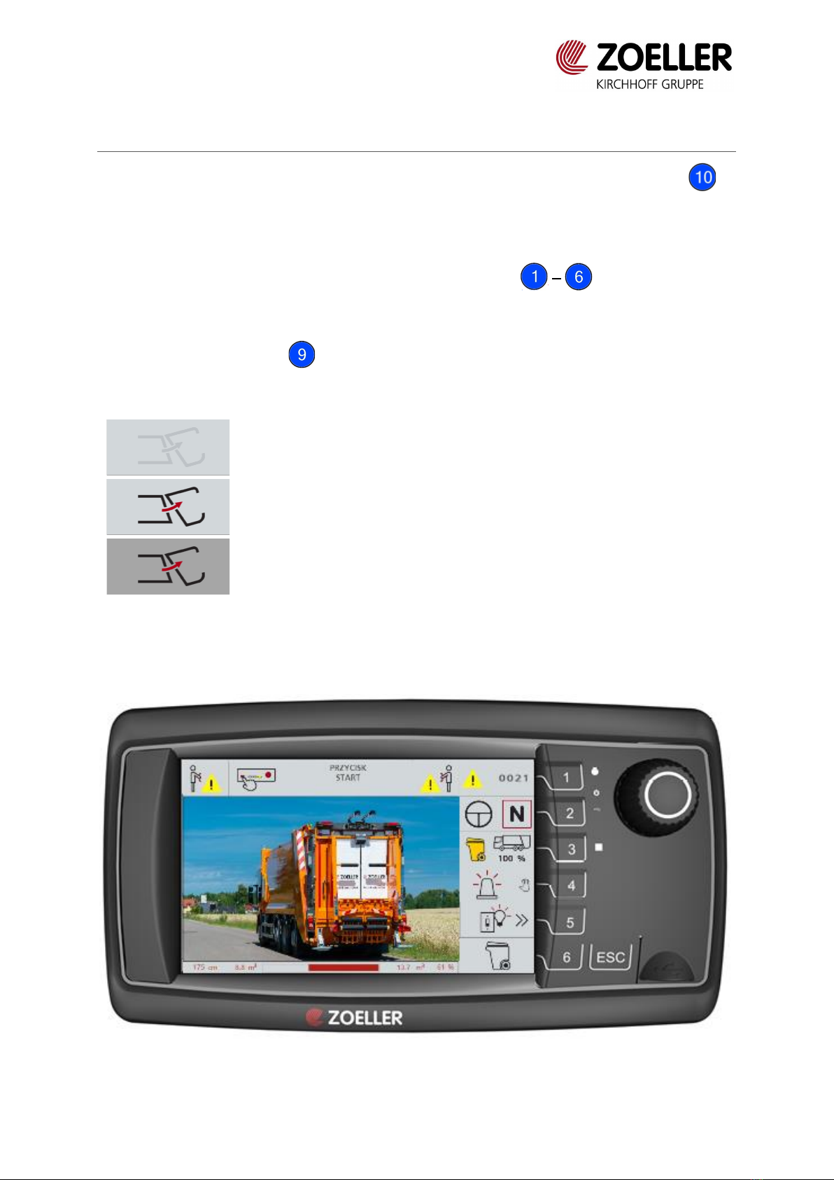
2.1 Terminal ZCS............................................................................................................................................ 4
2.2 ZCS-Command module....................................................................................................................... 5
3Operating.......................................................................................................................6
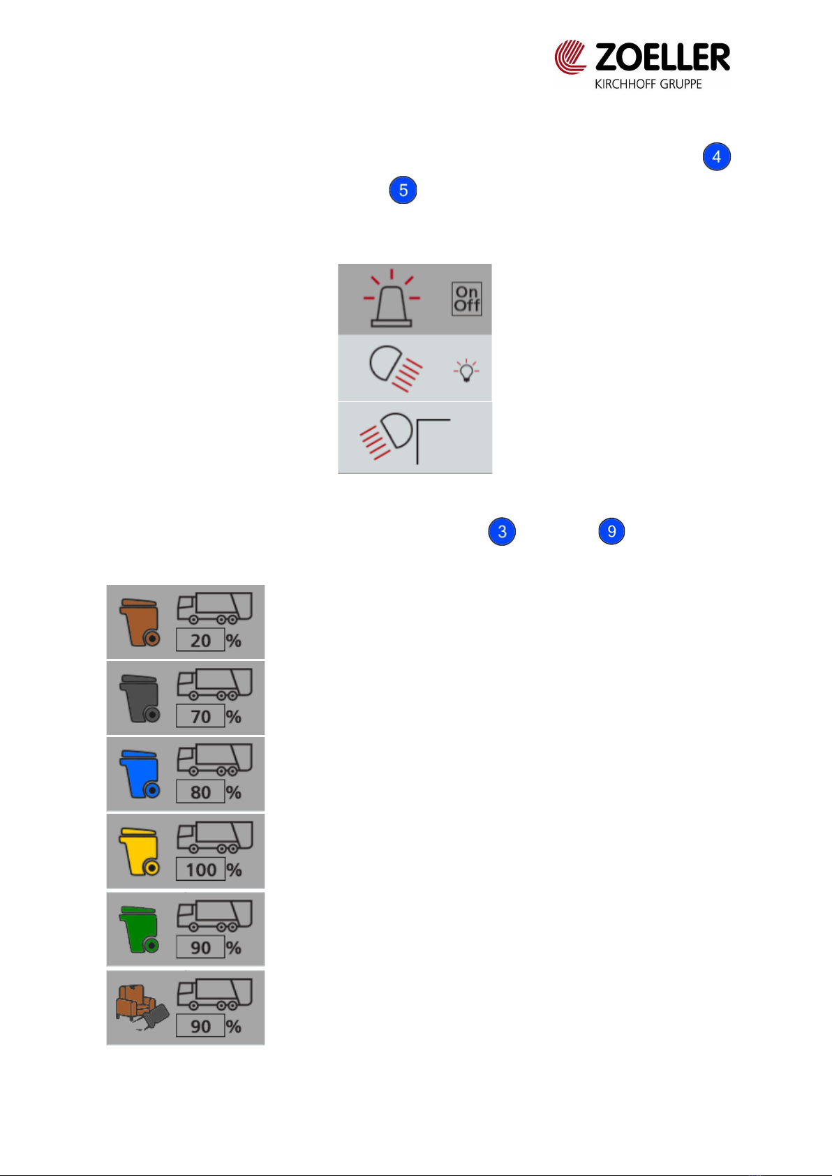
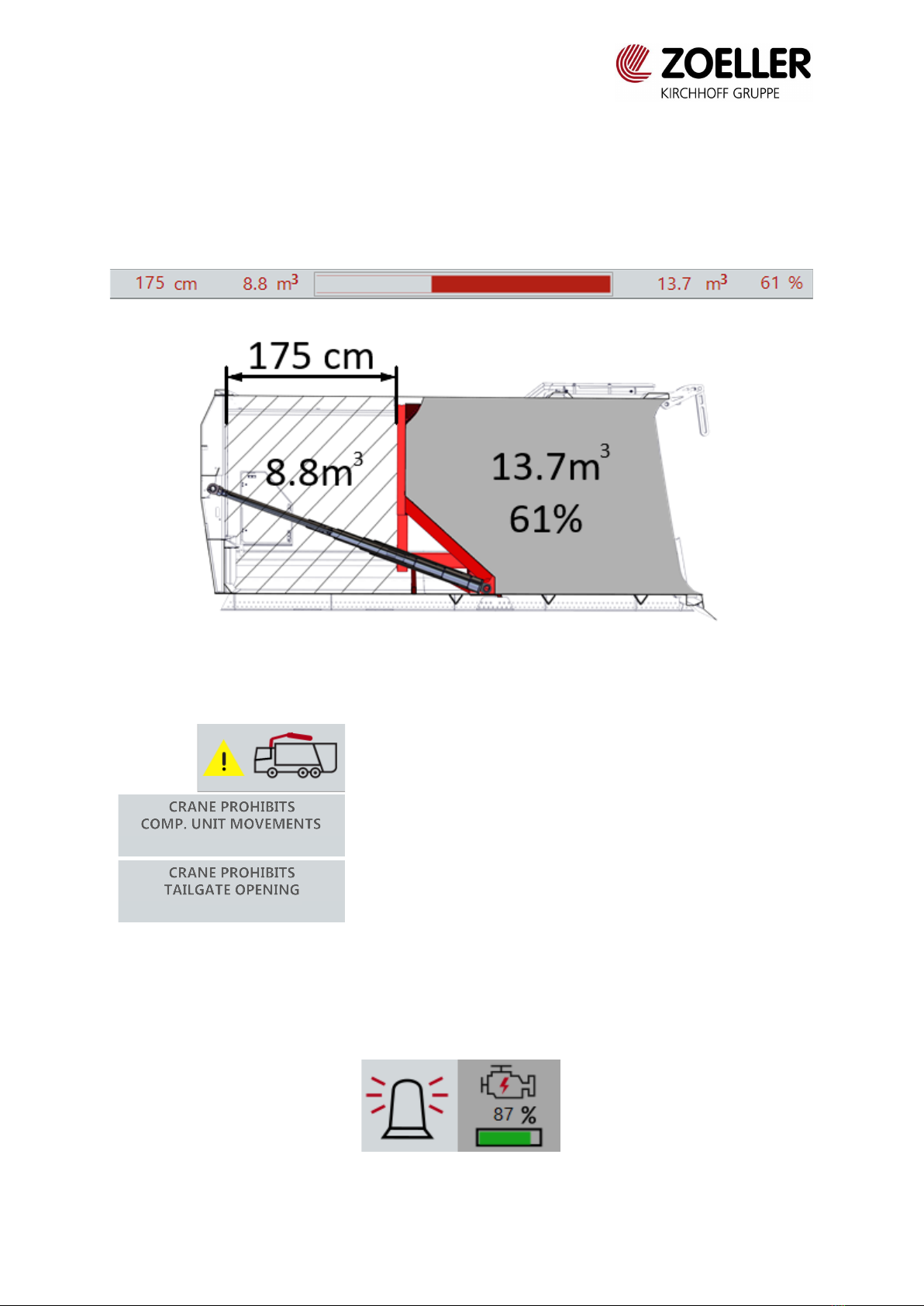
3.1 Main screen.............................................................................................................................................. 6
3.2 RCV Parameters ....................................................................................................................................10
3.3 Maintenance ..........................................................................................................................................11
3.4 Counter ....................................................................................................................................................12
3.5 Emptying .................................................................................................................................................13
3.6 Packing configuration.........................................................................................................................14
3.7 Lifter configuration..............................................................................................................................15
3.8 Video configuration.............................................................................................................................17
3.9 Other function configuration...........................................................................................................18
3.10 Calibration menu..................................................................................................................................21
3.11 Weighing system menu.....................................................................................................................21
3.12 Menu documentation.........................................................................................................................22
4Symbols........................................................................................................................23
5Error messages.............................................................................................................25

Guide 2
1GUIDE
This operating manual applies to Terminal ZCS.
All users of the terminal or persons carrying out maintenance and repair work must be trained
for the appropriate operation of the terminal.
ZOELLER TECH Sp. z o. o. assumes no liability or warranty for:
ouse of the terminal for other purposes than indicated in this manual
odamages which are due to negligent operation
odamages resulting from manipulation with terminal
Please study the operating instructions closely before operating the terminal.
1. SYMBOLS USED IN THIS MANUAL
When studying these operating instructions, you will notice a number of symbols and text
formats designed to give you a visual orientation in this manual. The following five symbols
are of major importance since they indicate such information or warnings which you must
absolutely take account of when using the terminal.
DANGER
These warnings indicate dangerous situations which cause immediate injury to people and must be
observed. Severe injuries or death can be caused by disregarding these warnings.
WARNING
These warnings give you important information on how to avoid dangerous situations and what to do in
cases of emergency or any malfunction.
ATTENTION
These phrases warn about possible damage to the vehicle itself or its direct environment which may
occur if the instructions are ignored.
IMPORTANT
Passages marked with this symbol contain important instructions and functional characteristics of the
vehicle.

Guide 3
FOR YOUR INFORMATION
This symbol indicates helpful advice on how to use the vehicle.
Components
This format is used to mark main components and operational controls in pictures and text
passages.

Main components 4
2MAIN COMPONENTS
2.1 TERMINAL ZCS
Fig. 2.1 Elements of ZCS terminal
Function buttons
ESC
USB port
Knob

Main components 5
2.2 ZCS-COMMAND MODULE
Fig. 2.2 ZCS Command module
START button
A1 button
A2 button
Restriction override button
Emergency stop button

Operating 6
3OPERATING
Terminal turns on automatically with the ignition. To start work, press START button on
ZCS-Command module after turning on the terminal.
Selection and confirming functions:
1. Function can be selected by pressing function buttons
or
2. By turning the knob and pressing it to confirm the choice.
Function status indications:
Function unavailable
Function available, inactive
Function available, active
3.1 MAIN SCREEN
Fig. 3.1 Main screen

Operating 7
Main screen displays all error messages and information e.g. information about weighted
footboards or opened tailgate. List of icons and error messages are shown in chapters 4 and 5.
On the background of the main screen video from CCTV is displayed. Using buttons
warning lights can be switched on. Button turns on working lights (back and side, if they
are installed). Pressing the button turns on or turns off the light. Activating the button is
signaled by the icon changing to dark gray.
Fig. 3.2 Turned on warning lights
It is possible to choose waste fraction using button and knob . Fractions are
represented by icons:
Bio waste
Mixed waste
Paper
Plastics
Glass (option)
Bulky waste

Operating 8
Using the knob and/or button one of menus can be selected:
RCV Parameters
Maintenance
Counter
Emptying
Packing configuration
Lifter configuration for small containers
Lifter configuration for large containers
Video configuration
Other function configuration
Calibration menu
Weighing system menu
Menu documentation

Operating 9
Options:
Pushing wall laser sensor:
If body is equipped with pushing wall laser sensor, on the bottom of main screen information
about position of pushing wall (distance between wall an front frame), left volume and
percentage of body loading are displayed. Figure below shows example of values.
Fig. 3.3 Example values and explanation
If body is equipped with crane, terminal displays messages if crane is not in transport position.
Crane is not in transport position
Crane is not retracted and disables compaction
mechanism operation
Crane is lifted and disables tailgate operation
Banke:
If body is equipped with Banke generator, the additional icon is available on the main screen
(next to warning lights icon):
Fig. 3.4 Banke icon on main screen

Operating 10
Long pressing of button turns on and off Banke pump, short pressing allows to adjust
warning lights. Light grey color of the icon means, that pump is off, dark grey means that it is
ready to use, and flashing of the icon signalize the error (e.g. low battery level). Error code is
displayed in right upper corner. Bar on the bottom of the icon shows percentage of battery
charge.
3.2 RCV PARAMETERS
RCV Parameters menu is used to preview the set parameters and to upload and download
parameters from an external drive.
Fig. 3.5 RCV Parameters menu
Button allows to search parameters by number. To select the required number, turn the
knob until the required digit is indicated, then confirm by pressing the knob and move to
the next digit. After entering the entire number, confirm the selection by pressing the button
.
In order to upload parameters from an external drive, insert the USB flash drive into the USB
port and press the button . The data will be uploaded automatically.
The button is used to download the set parameters to an external drive. The downloading
procedure is the same as uploading.

Operating 11
Fig. 3.6 Progress bar of uploading data
3.3 MAINTENANCE
The maintenance menu provides an overview of the status of the sensors.
Fig. 3.7 Maintenance menu

Operating 12
3.4 COUNTER
Counter menu is used to checking the counters for compaction cycles number, engine running
time etc. To reset the counters, press and hold button .
Fig. 3.8 Counter menu
Number of counters can vary depending on installed options. Daily time is counted in
minutes, total time is counted in hours.
Service interval –days left
Number of days until next service inspection
Service interval –hours left
Number of work hours until next service inspection
Greasing low –hydraulic
working time
The counter value is increased when a low grease level
is detected and there is a need for oil by any function.
Compaction cycles number
Daily and total value of the counter is increased every
time slider start moving up
Emptying cycles number
Daily and total value of the counter is increased every
time systems detects open position of tailgate
Lifter cycles number
Daily and total value of the counter is increased every
time lifter is lowered
The number of kilometers
traveled
The number of kilometers traveled is taken from the
chassis via the CAN connection.

Operating 13
Waste collection day number
Daily and total value of the counter is increased if in day
at least 10 press cycles was performed
Vehicle stopped for wastes
collection
Daily and total value of the counter is increased every
time the vehicle is stopped and there is demand for
hydraulic pressure
Engine running time
The value of the counter is increased when engine
speed is greater than zero. In case of lack of information
about vehicle speed, system detects engine state every
time the ignition is on
Waste collection time
Daily and total value of the counter is increased when
the vehicle is ready to work. Vehicle is ready to collect
waste when pump is on –start button on Command
Module is on
Running time vehicle at neutral
position
Daily and total value of the counter is increased when
the vehicle is stopped (N on the screen) and ready to
work
Compaction running time
Daily and total value of the counter is increased when
press oil demand is greater than zero
Lifter running time
Daily and total value of the counter is increased when
lifter oil demand is greater than zero
Hydraulic running time
Daily and total value of the counter is increased when
the vehicle is stopped (N on the screen) and pump is on
(Start button on Command Module)
3.5 EMPTYING
Emptying menu allows to control the tailgate and the pushing wall from the terminal. Holding
button opens the tailgate. Button closes it and it is active only when the tailgate is
opened. Tailgate cannot be closed fully from the terminal it has to be closed completely with
the buttons on the side of the body. Button retracts the pushing wall and button
ejects it - it is active only when the tailgate is closed.

Operating 14
Fig. 3.9 Emptying menu
If vehicle is equipped with control buttons on the front of body, it is necessary to choose using
button if tailgate is closed/opened with buttons or from the terminal. When control by
buttons on the body was chosen, control from terminal is unavailable. When control from
terminal was chosen, buttons on the body are disabled.
3.6 PACKING CONFIGURATION
Packing configuration menu allows to adjust the numbers of cycles of press in automatic mode.
Button sets the number of cycles during the collection of waste. Button sets the
number of cycles during the moving the vehicle, and button sets the number of cycles
during opening the tailgate.

Operating 15
Fig. 3.10 Packing configuration menu
3.7 LIFTER CONFIGURATION
Lifter configuration menu allows to set press parameters related to lifter.

Operating 16
Fig. 3.11 Lifter configuration –small containers
Button allows to set after how many lifter cycles the press will activate.
Button allows to decide which part of the compaction mechanism will be stopped during
the lifter operation (to avoid collision):
0. Press is not stopped
1. Slider is stopped
2. Slider and scraper are stopped
Button allows to see second page of a menu, where using button it is possible to
set when lifter positions to transport position.
Lifter moves to transport position when vehicle reaches a speed of 6 km/h
Lifter moves to transport position when reverse gear is engaged
Lifter moves to transport position when vehicle reaches a speed of 6 km/h or
when reverse gear is engaged
Lifter moves to transport position when reverse gear is engaged or when stop
conditions are not met (neutral gear is not engaged and no brake is pressed)

Operating 17
Lifter will not set to transport position automatically
Lifter moves to transport position when breaks are released, and lowers when
vehicle speed drops below the set speed (usually 3 km/h). The lifter will also raise
when the R gear is active.
3.8 VIDEO CONFIGURATION
Video configuration menu allows to adjust parameters, such as:
•Icon contrast
•Backlight
•Buzzer volume
•Date and time
•Language
•Contrast
•Brightness
•Color saturation

Operating 18
Fig. 3.12 Video configuration menu
3.9 OTHER FUNCTION CONFIGURATION
Other function configuration menu allows to set:
•Operating mode of the lighting
Fig. 3.13 Lighting mode menu

Operating 19
Mode of warning lighting can by set using button and knob. There are four modes to
set:
The lights turn on automatically when a hydraulic function is activated (e.g. moving
press, lifter). They turn off when the hydraulic functions are turned off. They can also
be turned on and off manually.
The lights turn on automatically when the gear is in neutral and the hydraulic
function is activated. The lights are turned off when N gear is disengaged. They can
also be turned on and off manually.
The lights turn on automatically when the vehicle speed is less than or equal to 6
km/h and the hydraulic function is activated. The lights are turned off when the
speed exceeds 6 km/h. They can also be turned on and off manually.
The lights turn on automatically when the vehicle speed is less than or equal to 30
km/h and the hydraulic function is activated. The lights are turned off when the
speed exceeds 30 km/h. They can also be turned on and off manually.
The working lights can be configured by entering the submenu for the selected lights (on the
tailgate, on the upper side of the body, under the body). In the submenu, you can set different
light triggers and necessary conditions - you can turn on several triggers and conditions
simultaneously.
The lights turn on automatically when a hydraulic function is activated
(e.g. moving press, lifter). They turn off when the hydraulic functions are
turned off. They can also be turned on and off manually.
The lights turn on automatically when reverse gear is engaged. They turn
off when reverse gear is disengaged, after a defined period of time. The
time until the lights turn off can be set between 0-9 seconds. To do this,
hold down the function button for a while and change the value using
the knob. The lights can also be turned on and off manually.
This is a necessary condition - the lights only turn on when the vehicle's
running lights are on.
This is a necessary condition - the lights only turn on when the brake is
applied.
This is a necessary condition - the lights only turn on when the vehicle
does not exceed the set speed. The speed (from 0 to 30 km/h) can be
set by holding down the function button and selecting the value using
the knob.
Table of contents
Popular Touch Terminal manuals by other brands

Mitsubishi Electric
Mitsubishi Electric E1071 installation manual

eyecool
eyecool ECX333 user manual

Newland
Newland NQuire 1000 Manta II quick start guide

Ingenico group
Ingenico group iSMP v4 Wi-Fi manual

Siemens
Siemens SIMATIC HMI IPC477C PRO Comapct operating instructions

Intertec Data Systems
Intertec Data Systems SuperTerm Maintenance manual