© Copyright 2014 Zoeller®Co. All rights reserved.
This utility pump is designed for general commercial and industrial
applications. Unit is designed for water, but is not submersible. For use
transferring liquids, emptying or lling tanks, sinks or bowls. Self-priming
to 7 ft. if the impeller is initially wet (primed). Intermittent duty. NOTE: Unit
DESCRIPTION
is NOT RECOMMENDED for use with soap detergents, gasoline, fuel oil,
ammable, explosive or combustible liquids or other uids not compatible
with pump component materials. Do not use unit in enclosed areas.
INSTALLATION
SK2206
1. Pump should be placed as close to source of liquid and power as
possible, not more than 7 feet above liquid source if self-priming,
and not more than 25 feet from power source.
2. Use reinforced plastic or fabric tubing or metal pipe for the suction
side of the pump. This will prevent collapse of the suction piping.
Discharge piping should never be larger than suction piping!
3. Attach suction line piping to the suction inlet and discharge line piping
to the discharge outlet.
4. Avoid using looped sections of pipe which might permit air to become
entrapped.
5. Piping should be checked for any leaks at the connections. Small
leaks in suction line greatly reduce efciency of pump, and may
prevent priming. (Never operate a pump unless it is secured to a
solid foundation.)
6. Do not operate pump dry. Impeller and seal damage will result.
7. Protect pump from extreme heat, cold, and humidity. This unit is not
waterproof and is not intended to be used in showers, saunas, or
other potentially wet locations. The motor is designed to be used in
a clean, dry location with access to an adequate supply of cooling
air. Ambient temperature around the motor should not exceed 104°F
(40°C). This unit is not weatherproof, nor is it able to be submersed
in water or any other liquid.
8. Install a foot valve and prime pump when suction lift is over six feet
or when suction line is longer than six feet.
9. Itisstrongly recommended that the Model311ispluggedintoa G.F.C.I.
(Ground Fault Circuit Interrupter). Consult your local electrician for
installation and availability.
OPERATION
1. Model 311 is self-priming and should prime itself within 30 seconds
after pump is started. Wetting impeller with pumped uid and keeping
the impeller coated with petroleum jelly will lengthen its life and
improve priming action. Running the impeller dry for as short as 30
seconds can ruin the impeller (Ref. No. 5). Keep suction line as short
as possible.
NOTE: An easy way to prime the pump (wet impeller), if using a garden
hose, is to ll the discharge hose; elevate the discharge hose slightly to
retain water and start the pump. Another method would be to disconnect
the discharge hose from the pump, making a U-bend of the discharge
hose, ll the hose and then reconnect to the pump (without losing the
water). In both cases, the water behind the impeller will seal the pump
and it will prime almost immediately.
2. Be sure hose attachments or piping connections are tight. Any
leakage in suction side will prevent pump from priming.
MAINTENANCE
1. Always drain pump when not in use.
2. If pump is not going to be used for a month or longer, ush with fresh
water and remove body cover, take impeller out, clean inside body
and apply generous coating of petroleum jelly to both inside body and
impeller before replacing impeller in body.
3. Pump should be checked daily, weekly, monthly, etc. for proper
operation. If anything has changed since unit was new, unit should
be removed and repaired or replaced. Only qualied electricians or
servicemen should attempt to repair the motor of this unit. Improper
repair and/or assembly can cause an electrical shock hazard.
HOW TO REPLACE IMPELLER
Replace impeller when it has been worn or damaged by foreign objects,
pumping improper liquid or dry running.
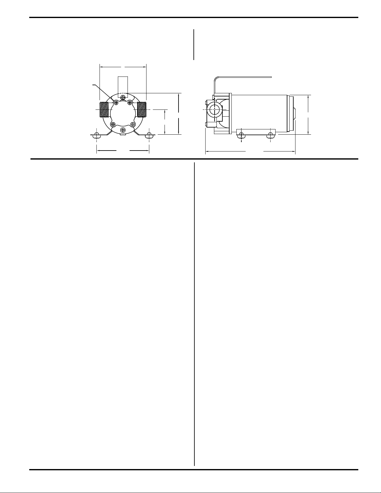
1. Remove four screws at “A” (see gure above).
2. Remove cover plate.
3. Using your ngers, remove damaged or worn impeller.
4. Clean the inside of the pump head and remove any foreign materials
which will obstruct the impeller’s operation.
5. Apply petroleum jelly or similar lubricant to both the inside of pump
head and to the outside diameter of the impeller.
6. Align the at on the inside of the new impeller with the at on the motor
shaft. Push into place while twisting blades in a clockwise direction.
7. Place new gasket on pump body face, align holes and replace cover.
8. Tighten all four screws evenly and snugly.
9. Replacementimpeller/gasket kits areavailableas part number015391.
"A"
2 17/32
5 25/32
3 3/8
3
1 19/32
2 21/32