manuals.online logo
Brands
  1. Home
  2. •
  3. Brands
  4. •
  5. Zoeller
  6. •
  7. Water Pump
  8. •
  9. Zoeller 370-0002 User manual

Zoeller 370-0002 User manual

© Copyright 2010. All rights reserved.
1
SECTION: 6.10.143
FM2340
0110
Supersedes
1006
INSTALLATION INSTRUCTIONS
These installation instructions are applicable for Model 370-0002Aeration/Fountain Pump only.
This pump system is designed for decorative use and can improve water aeration.
Notice to Installer: Instructions
must remain with installation.
Product information presented
here reflects conditions at time of
publication.Consultfactoryregarding
discrepancies or inconsistencies.
MAIL TO: P.O. BOX 16347 • Louisville, KY 40256-0347
SHIP TO: 3649 Cane Run Road • Louisville, KY 40211-1961
(502) 778-2731 • 1 (800) 928-PUMP • FAX (502) 774-3624
PREINSTALLATION CHECKLIST - ALL INSTALLATIONS
AERATION/FOUNTAIN PUMP MODEL 370-0002
visit our web site:
www.zoeller.com
ATTENTION:READCAREFULLYBEFOREATTEMPTINGTO INSTALLOROPERATEYOURPUMP.PROTECTYOURSELFANDOTHERSBYOBSERVINGALL
SAFETYINFORMATIONANDADDITIONALINSTRUCTIONS INCLUDED WITH EQUIPMENT.FAILURETOCOMPLYWITH INSTRUCTIONS COULD RESULTIN
PERSONALINJURYAND/OR PROPERTY DAMAGE! RETAIN FOR FUTURE REFERENCE.
SEE BELOW FOR LIST OF WARNINGS
1. Makesurethatthepumpispluggedintoaproperlygroundedelectri-
cal receptacle. Use an Underwriters Laboratory listed circuit analyzer
to test for proper installation of the circuit and ground. Any service to
circuits or receptacles should be conducted by a qualified licensed
electrician.
2. Donotremovethegroundpinfromtheplugunderanycircumstances.
If the ground pin is damaged, replace the power cord or plug before
use.
3. AllelectricalinstallationsmustconformtotherequirementsoftheNational
Electrical Code and all local codes.
4. System furnished with a 100 ft. power cord with 3-prong GFCI plug;
mustconnect toproperlygroundedreceptacleof groundingtype. Donot
removeground pin onplug. Do notextend the cord length bysplicing or
with an extension cord.
5. Disconnectpowerbeforeservicingthepumpormotorbyunplugging
the unit from the outlet.
6.
Do not touch the motor when operating and allow the motor
to cool before touching.
7. Pump isbuilt tohandle clearwateronly; itis notdesignedto handlewater
containing sand, silt or other abrasives.
8. Do not use to pump flammable or explosive fluids such as
gasoline,fueloil,kerosene,etc. Donotuseinflammableand/
or explosive atmospheres.
9. Donotusethisproductinhazardousenvironmentsoranywhere
a spark could potentially ignite explosive gases.
10. Do not handle this product with wet hands or while standing in water or
on a wet or damp surface.
11. Unitsaresuppliedwithanautomaticallyresettingthermaloverloaddevice
and can restart without warning.
12. Provide a means of pressure relief if the pump discharge can
be shut off or obstructed. Pumps operating against a closed
dischargecan create veryhot pumped liquid,whichcan cause
burns.
13. "NoSwimming"and/orwarningsignsshouldbepostedperstateandlocal
codes. Pleaseaffixincludedwarninglabeltopowerreceptacleorjunction
box.
14. Do not ground to a gas supply line.
15. Protect the power cable from coming in contact with sharp objects, oil,
grease hot surfaces or chemicals. DO NOT kink the power cable. If
damaged, replace immediately.
16. AccordingtothestateofCalifornia(Prop65),thisproductcontainschemi-
cals known to the state of California to cause cancer and birth defects or
other reproductive harm.
17. NEVER leave the control box, fused disconnect switch or cover open
(either partially or completely) when not being worked on by a competent
electrician.
18. Water leaving nozzle is at high velocity and can cause bodily injury if
contact is made.
19. Never examine, make wiring changes or touch the motor before discon-
necting the main electrical supply switch. The thermal device may have
opened the electrical circuit. All motors should be equipped with a cor-
rectly fused disconnect switch to provide protection. Consult local or
United States National Electrical Codes for proper fuse protection based
on motor data chart.
20. GFIplug must beoriented with cordcoming out the bottom and protected
from direct rainfall.
1. Makecertain that the powersourceconformstothe requirements of the
equipment as stated on the product nameplates and wire motor for cor-
rect voltage. See motor nameplate.
2. Periodically inspect the pump for damage and perform routine
maintenance as required.
3. The maximum temperature of the pumped liquid must not exceed
120°F.
4. Supply voltage must be within ± 10% of nameplate voltage. Incorrect
voltage can cause fire or seriously damage motor and voids warranty. If
in doubt, consult a licensed electrician.
REFER TO WARRANTY ON PAGE 2.
SEE BELOW FOR LIST OF CAUTIONS
021766
© Copyright 2010. All rights reserved.
2
Manufacturerwarrants,tothepurchaserandsubsequentownerduringthewarranty
period, every new product to be free from defects in material and workmanship
under normal use and service, when properly used and maintained, for a period
of one year from date of purchase by the end user, or 18 months from date of
original manufacture of the product, whichever comes first. Parts that fail within
the warranty period, one year from date of purchase by the end user, or 18
months from the date of original manufacture of the product, whichever comes
first, that inspections determine to be defective in material or workmanship, will
be repaired, replaced or remanufactured at Manufacturer's option, provided
however,thatby so doing we will not be obligatedto replaceanentireassembly,
the entire mechanism or the complete unit. No allowance will be made for ship-
ping charges, damages, labor or other charges that may occur due to product
failure, repair or replacement.
This warranty does not apply to and there shall be no warranty for any material
or product that has been disassembled without prior approval of Manufacturer,
subjectedtomisuse,misapplication,neglect,alteration,accidentoractofGod;that
hasnotbeeninstalled,operatedormaintainedinaccordancewithManufacturer's
installation instructions; that has been exposed to outside substances including
but not limited to the following: sand, gravel, cement, mud, tar, hydrocarbons,
hydrocarbonderivatives(oil,gasoline,solvents,etc.),orotherabrasiveorcorrosive
substances,washtowelsorfemininesanitaryproducts,etc.inallpumpingapplica-
LIMITED WARRANTY
tions. Thewarrantysetoutintheparagraphaboveisinlieuofallotherwarranties
expressedorimplied;andwedonotauthorizeanyrepresentativeorotherperson
to assume for us any other liability in connection with our products.
ContactManufacturerat, 3649 CaneRunRoad,Louisville,Kentucky 40211,At-
tention:CustomerServiceDepartmenttoobtainanyneededrepairorreplacement
of part(s) or additional information pertaining to our warranty.
MANUFACTUREREXPRESSLYDISCLAIMSLIABILITYFORSPECIAL,CON-
SEQUENTIALORINCIDENTALDAMAGESORBREACHOFEXPRESSEDOR
IMPLIED WARRANTY;ANDANY IMPLIED WARRANTY OF FITNESS FORA
PARTICULAR PURPOSEAND OF MERCHANTABILITY SHALL BE LIMITED
TO THE DURATION OF THE EXPRESSED WARRANTY.
Some states do not allow limitations on the duration of an implied warranty, so
theabovelimitationmaynotapplytoyou.Somestatesdonotallowtheexclusion
or limitation of incidental or consequential damages, so the above limitation or
exclusion may not apply to you.
This warranty gives you specific legal rights and you may also have other rights
which vary from state to state.
ELECTRICAL PRECAUTIONS - Before servicing a pump, always shut off the main power breaker and then unplug the pump. Make
sure you are not standing in water and are wearing insulated protective sole shoes. Under flooded conditions, contact your local electric company or a
qualified licensed electrician for disconnecting electrical service prior to pump removal.
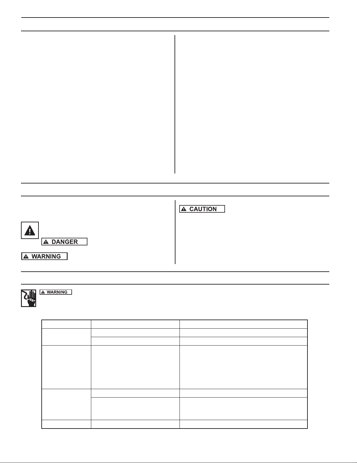
TROUBLE SHOOTING GUIDE
SYMPTOM POSSIBLE CAUSES CORRECTIVE ACTION
Unit won’t run. Circuit breaker tripped. Reset circuit breaker.
GFCI tripped. Reset GFCI.
No or low spray. Blocked screen or nozzle, missing
or damaged o-ring, or incorrectly
installed nozzle.
Disconnect power. Clean screen and/or nozzle.
Check that o-ring is undamaged and seated in
groove. Check that nozzle is installed properly
(nozzles are marked “This side up”). Check depth of
pond. If less than 5 feet deep, move to deeper sec-
tion. Restart unit.
GFCI trips. Electrical storm can trip GFCI. Reset GFCI.
Short in system. Disconnect power and check cord for damage. If
cord is damaged contact Customer Service Help
Line at 1-800-928-7867.
Unit spins. Anchor rope loose. Check anchor rope and re-attach if necessary.
SAFETY INSTRUCTIONS
Carefully read and follow all safety instructions in this manual and on
pump. Keep safety labels in good condition. Replace missing or damaged
safety labels.
This is a SAFETY ALERT SYMBOL. When you see this symbol on
thepumporinthe manual,look for oneofthe following signal words
and be alert to the potential for personal injury or property damage.
Warns of hazards that WILL cause serious
personal injury, death or major property damage if ignored.
Warns of hazards that CAN cause serious personal
injury or death, if ignored.
Warns of hazards that MAY cause minor personal
injury, product or property damage if ignored.
IMPORTANT: Indicates factors concerned with operation, installation, assembly
or maintenance which could result in damage to the machine or equipment if
ignored.
NOTE: Indicates special instructions which are important but are not related to
hazards.
© Copyright 2010. All rights reserved.
3
1. Only install this system in ponds where no swimming, wading, boating or
fishing is allowed. Disconnect power to pump before fishing or entering the
water.
2. Post appropriate warning signs per local and state codes.
3. Inspect pump system for damage before installing in pond. Check that all
bolts and screws are tight. Check for any bent prongs or a cracked case on
the GFCI.
4. The unit ships with one spray nozzle attached. To change to one of the other
2 nozzles, remove the 4 screws from the nozzle then replace with desired
nozzle. Refer to Figures 2, 3 & 4 for spray pattern appearance. Nozzles
are marked “This side up.” Make sure the o-ring is seated in groove before
installing nozzle. Tighten screws until seated, approximately 10 to 12 in-lbs.
5. Attach nylon anchor ropes to 2 eyebolts located at top of screen. Secure
(make sure rope is tight) to weights placed on pond floor or stakes on pond
shore.Whenusingweightstoanchorthepump,placeweightsapproximately
10 feet from unit, 180 degrees apart.
6. Before connecting the unit to the power receptacle, check to insure there is
no leakage to ground. This can be done by using an ohm meter and setting
the scale to its highest setting (i.e. Rx100K). Connect one ohm meter lead
to the unit power cord ground (round prong) and to one of the flat prongs. It
should read infinite or at least 2 megohms. Repeat with the other prong. If
readingis below 2megohms on eitherprong, contact TechnicalServiceHelp
Line at 800-928-7867.
7. Do Not Operate System on an Extension Cord. If no power is accessible at
the pond, contract a licensed electrician to install the proper power supply in
accordance with National Electrical Code and all applicable local codes and
ordinances.
8. After installing the unit, checking ground and connecting power to the unit,
the unit can be powered up. Check operation of the GFCI by pushing the
“Test” button, the unit should stop. Pushing the “Reset” button should restart
the unit. If pressing the “test” button does not stop the unit, immediately shut
off power to unit and contact Technical Service Help Line at 800-928-7867.
INSTALLATION
INSTALLATION CHECK LIST
Read installation instructions and warnings.
Post appropriate warning signs.
Install desired spray nozzle.
Install and anchor unit in pond.
Check insulation resistance to ground.
Power up unit.
Test operation of GFCI by pressing the “Test” Button.
File instructions for future reference.
REQUIRED TOOLS & SUPPLIES
• #2 Phillips screwdriver to change nozzles.
• Nylon rope to anchor unit.
• Stakes or weights for anchoring unit.
• Ohm meter to check insulation resistance to ground.
WINTER STORAGE
• Rinse unit with clean water to remove any build-up on unit.
• Check unit for any damage.
• Store unit in heated space in freezing climates.
The pump motor is water lubricated and is factory filled with an antifreeze solu-
tion.During operation the antifreeze mayexchange, thru thefiltered check valve,
with the pond water. In climates where freezing may occur, the unit must be
stored in a heated storage space to prevent damage to the motor.
Figure 1: Typical Installation
IL0535
Pond Pump Float
Nylon rope secured to weights
can be attached to stakes on
shore. 2 Required.
5 Feet Minimum Depth
Approved outdoor grounded
receptacle with GFI protected plug
Power cord may require
burial. Refer to local codes
15 - 20
Feet
IL0535
Figure 2: Sky Cannon - A dramatic single plume of water. Part #2B
Figure 3: Water Lily - An eye-catching combination spray. Part #2A Figure 4: Water Trumpet - A symmetrical inverted bell shape. Part #2C
© Copyright 2010. All rights reserved.
4
INTERNAL PARTS
Item # Qty Part No. Description
1 6 021624 Screw - #10 x 3/4 Pan Head High-Low
2A 1 021617 Nozzle - Water Lily
2B 1 021618 Nozzle - Sky Cannon
2C 1 021619 Nozzle - WaterTrumpet
3 1 021622 O-Ring -AS568A - 041 (3" ID x 3/18" OD)
4 6 021628 Bolt - SS 1/4-20 x 3/4
5 6 021629 Lockwasher - 1/4"
6 1 021707 Mounting Flange
7 1 021534 Float
8 1 021713 Pump End
9 1 021740 Motor 1/2 HP 115V
10 4 127021 Locknut - SS 5/16-24
11 1 021715 100 ft. power cord with GFCI
12 2 021609 Eye Bolt - SS 1/4-20 x 2-1/2
13 2 021623 Locknut - SS 1/4-20
14 1 021608 Screen
15 1 021611 Screen Cap
16 1 021613 Strain Relief
17 2 021625 Warning Decal
Flow (GPH) Spray Height
(Ft.) Pattern Image Pattern Name
4900 15 Water Lily - 2A
3300 15 Sky Cannon
- 2B
2700 13 Water Trumpet
- 2C
T
h
i
s
s
i
d
e
u
p
T
h
i
s
s
i
d
e
u
p
T
h
i
s
s
i
d
e
u
p
15
16
11
IL0538
1
2(A/B/C)
3
6
7
17
10
9
11
13
12
14
1
15
11
4
5
8
IL0536
4
5

Other Zoeller Water Pump manuals

Zoeller 2701 User manual

Zoeller

Zoeller 2701 User manual

Zoeller SRS User manual

Zoeller

Zoeller SRS User manual

Zoeller 810 User manual

Zoeller

Zoeller 810 User manual

Zoeller 370-0002 User manual

Zoeller

Zoeller 370-0002 User manual

Zoeller 1043-0006Q User manual

Zoeller

Zoeller 1043-0006Q User manual

Zoeller 135-0006 User manual

Zoeller

Zoeller 135-0006 User manual

Zoeller X71 Series User manual

Zoeller

Zoeller X71 Series User manual

Zoeller 61 HD Series Operating instructions

Zoeller

Zoeller 61 HD Series Operating instructions

Zoeller LM44 User manual

Zoeller

Zoeller LM44 User manual

Zoeller AquaNot 507 Key User manual

Zoeller

Zoeller AquaNot 507 Key User manual

Zoeller 1099-0001Q User manual

Zoeller

Zoeller 1099-0001Q User manual

Zoeller 7020 User manual

Zoeller

Zoeller 7020 User manual

Zoeller 7020 User manual

Zoeller

Zoeller 7020 User manual

Zoeller 104 Series User manual

Zoeller

Zoeller 104 Series User manual

Zoeller 810 User manual

Zoeller

Zoeller 810 User manual

Zoeller SHARK 800 Series User manual

Zoeller

Zoeller SHARK 800 Series User manual

Zoeller 1104-0082 User manual

Zoeller

Zoeller 1104-0082 User manual

Zoeller 7008 User manual

Zoeller

Zoeller 7008 User manual

Zoeller QWIK JON PREMIER 201 User manual

Zoeller

Zoeller QWIK JON PREMIER 201 User manual

Zoeller 2701-0005 User manual

Zoeller

Zoeller 2701-0005 User manual

Zoeller ProPak AQUANOT KEY 507/73 User manual

Zoeller

Zoeller ProPak AQUANOT KEY 507/73 User manual

Zoeller 1104-0082 User manual

Zoeller

Zoeller 1104-0082 User manual

Zoeller 404/4404 User manual

Zoeller

Zoeller 404/4404 User manual

Zoeller X160 Series User manual

Zoeller

Zoeller X160 Series User manual

Popular Water Pump manuals by other brands

Pfeiffer Vacuum HENA 201 R operating instructions

Pfeiffer Vacuum

Pfeiffer Vacuum HENA 201 R operating instructions

Intex AP619RL owner's manual

Intex

Intex AP619RL owner's manual

RICE HYDRO TRH-2 operating instructions

RICE HYDRO

RICE HYDRO TRH-2 operating instructions

VADA SUMP PUMP V150 installation manual

VADA

VADA SUMP PUMP V150 installation manual

Crane ELRO IP 100 Installation and operation manual

Crane

Crane ELRO IP 100 Installation and operation manual

BRINKMANN PUMPS BE8082 operating instructions

BRINKMANN PUMPS

BRINKMANN PUMPS BE8082 operating instructions

WACKER Group PT 6LT Operator's manual

WACKER Group

WACKER Group PT 6LT Operator's manual

Lowara DOMO Quick start up guide

Lowara

Lowara DOMO Quick start up guide

CALPAK FlowSol S Manual for the specialised craftsman

CALPAK

CALPAK FlowSol S Manual for the specialised craftsman

Danfoss H1 115 technical information

Danfoss

Danfoss H1 115 technical information

Enerpac ZU4204BB-Q instruction sheet

Enerpac

Enerpac ZU4204BB-Q instruction sheet

Exhausto CONPUMP-AS Product information

Exhausto

Exhausto CONPUMP-AS Product information

Grundfos SCALA1 Installation and operating instructions

Grundfos

Grundfos SCALA1 Installation and operating instructions

Putzmeister P 718 TD Translation of the original operating instruction

Putzmeister

Putzmeister P 718 TD Translation of the original operating instruction

Hilintec C09 Series user guide

Hilintec

Hilintec C09 Series user guide

GIANT PUMPS GP8035 Repair instructions

GIANT PUMPS

GIANT PUMPS GP8035 Repair instructions

Larzep HEP0020 INSTRUCTIONS & MAINTENANCE SHEET

Larzep

Larzep HEP0020 INSTRUCTIONS & MAINTENANCE SHEET

GORMAN-RUPP PUMPS 02K31-X2 1P Installation, operation, and maintenance manual with parts list

GORMAN-RUPP PUMPS

GORMAN-RUPP PUMPS 02K31-X2 1P Installation, operation, and maintenance manual with parts list

manuals.online logo
manuals.online logoBrands
  • About & Mission
  • Contact us
  • Privacy Policy
  • Terms and Conditions

Copyright 2025 Manuals.Online. All Rights Reserved.