Zoltec BELTOMATIC User manual

OPERATORS MANUAL

To: Sales Order:
Number:
Date:
PO:
B.N.W. Industries Terms:
7930 N. 700 E. Amount
Tippecanoe, IN. 1
46570 USA
Office 574-353-7855
Fax 574-353-8152 Gas safety and modulating control valves
Email [email protected]
Web www.belt-o-matic.com Belt wiper product spreader, two 1-Hp drives
Mild steel construction, insulated, Zoltec Blue
Auto fines clean out in bottom plenum of dryer, 1-Hp drive
No pre--wired electric control panel
No variable speed drives for motors
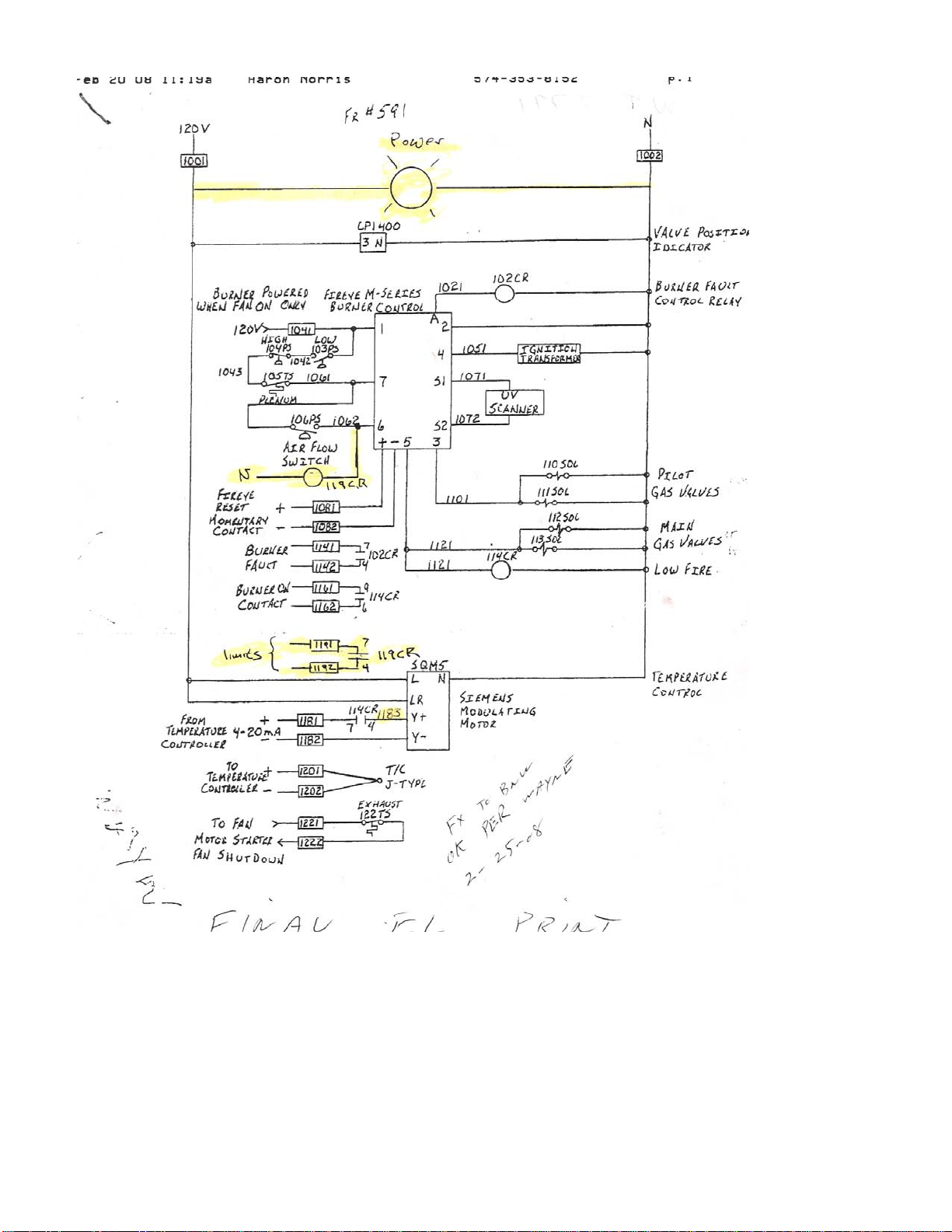
Fireye "M" series flame monitor, dwyer vacuum airflow
switch, ignition transformer, electric jct box (NEMA 4),
Important Note
% Down 35%
Entered By
:
Aaron Norris Total
Down Pmt
Received By: Balance
Date:
-$
All Prices in US Dollars
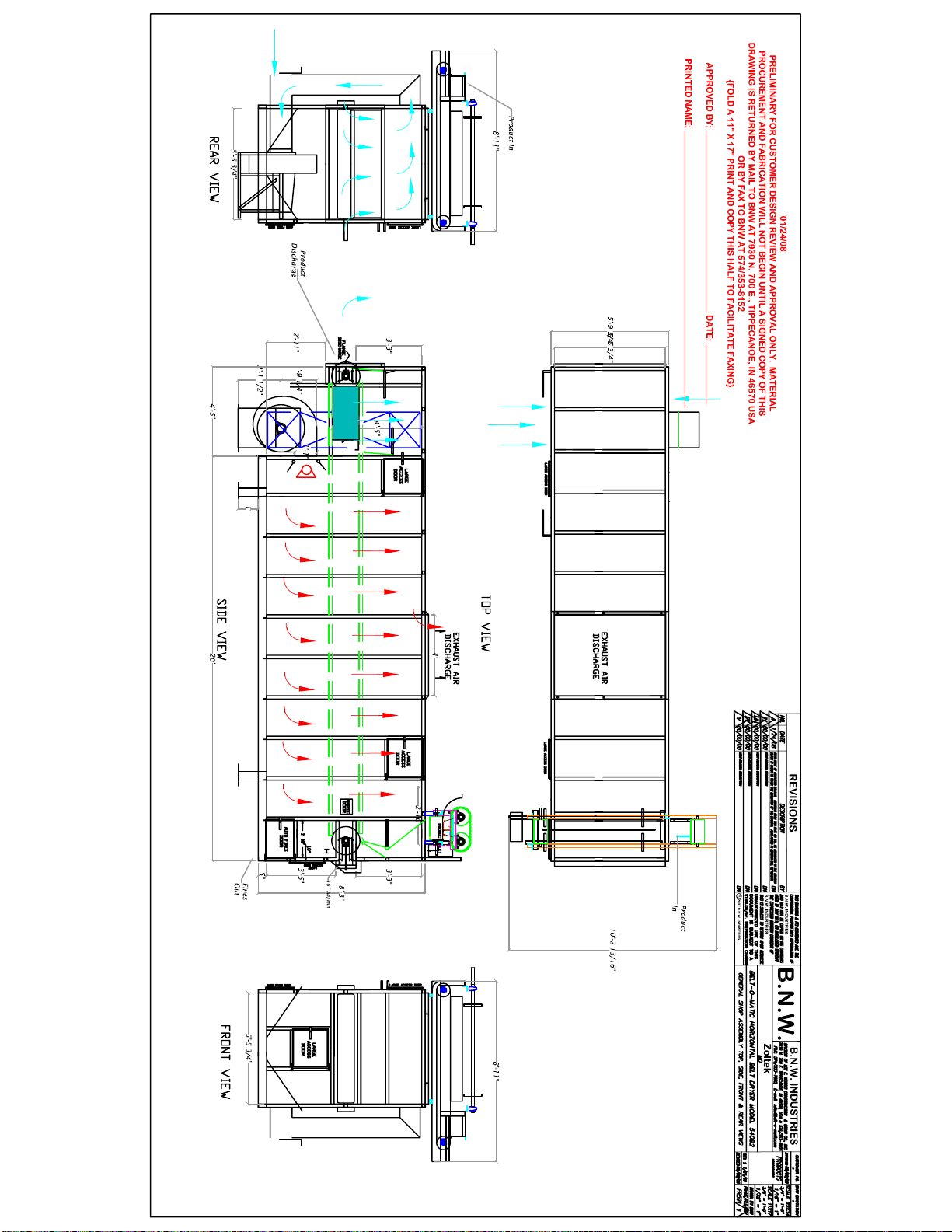
5' wide x 24' long, single-pass air up dry and cool
Belt-o-matic model 5-303B carbon pellet dryer/cooler
FOB Tippecanoe, IN, 46570. Allow 10 weeks ARO. Dated Required 2/15/08
35% down, 50% when ready to ship, 15% 30 days.
Description Price
Zoltec Corporation
Clancy Duttlinger
3101 McKelvey Road
St. Louis, MO. 63044
Product feed and discharge conveyors and fines discharge conveyor
and typical wiring scehmatic.
Not included
Air intake air duct
Motor controls for spreader, auto fines, and combustion blower
122670
All quotes are good for 30 days
Transportation, installation, and foundation
Electric power and gas supply
Pre-wired electric control cabinet
Temperature controller and thermocoupler
Variable speed drives for fan and conveyor motors
X
07247R3
1/7/2008
High temperature limit switches & dial temperature thermometers
Perforated plate conveyor belt with 0.078 x 0.156 slots, 304SS
3-Hp NYB combustion blower series 20 GI fan, 2500 CFM
3/4-Hp conveyor drive
TEFC premium efficiency motors 240/480 volt, 3 phase
Maxon Ovenpak gas burner, 750,000 Btu maximum
60" width belt w/ 2" tall side plates & 6" pitch mild steel roller chain
BNW Industries is not responsible for
compliance of required local, state,
and national regulatory guidelines
concerning gas, burner, and electrical
features. "As built" electrical
schematic is included. UL approved
electric enclosure available at an
additional cost. All pricing is for
budget purposes. Final pricing will be
submitted after approved engineering
drawings. B.N.W. Industries is NOT
responsible for any and all sales, use,
import or value added taxes.
Cyclone and fan for cleaning exhaust air & exhaust air duct
-$ -$


Table of Contents
I. Introduction pg. 1
A.Warnings
B. Equipment ID
C. Warranty
D. Disclaimer
II. Safety pg. 2
A. Fire Safety
B. Fire Safety Equipment on all New Belt-o-matic Dryers
1. Burner control power interlock
2. Airflow switch
3. High limit safety switches
C. Emergency Fire Shut Down Procedure
D. General Safety
III. General Information pg. 3
A. Manufacturer Information
B. Servicing Statement
C. Using the Manual
IV. Receiving and Handling pg. 4
A. Inspection
B. Damages
C. Handling
D. Packaging
V. Installation pg. 4
A. Installation Site
B. Electric Hook Up
C. Gas Hook Up
D. Assembly of Parts
1. Top cover and inlet hopper
2. Shaft-mounted gearboxes with C-face motors
3. Removed drive plate
4. Air intake duct
E. Air Ducts
F. Rotations and Alignments
G. Motors
VI. Operations pg. 7
A. Start-up Procedure
B. Shut Down Procedure
C. Filling the Machine, Product Depth
D. Adjustments and Controls
1. Depth
a. Inlet hopper and level gate
b. Inlet spreaders
2. Conveyor belt speed
3. Flame adjustment
4. Temperature adjustment
5. Airflow

E Controlling Capacity
F. Controlling Efficiency
VII. Maintenance pg. 12
A. Housekeeping
B. Bearing Service
C. Gearboxes
D. Chain Adjustments
E. Maintaining Woven Wire Conveyor Belt
1. Belt maintenance
2. Belt traction
3. Belt adjustments
4. Belt removal and replacement
F. Maintaining Solid Tray Conveyor Belt
1. Belt maintenance
2. Belt tension
3. Belt adjustments
4. Belt removal and replacement
G. Conveyor Racks
H. Drive Roller Lagging
VIII. Optional Equipment pg. 16
A. Auto Fines Clean Out Systems
B. Stirring Equipment
C. Cyclones
D. Stainless Steel Contact Points and Construction
E. Steam Heat Exchangers
F. AC Inverters
G. Inlet Level Beater
H. Rotary Air Locks
I. Auger Discharge
IX. Troubleshooting pg. 18
Appendix
Roller Adjustment for Discharge Drive (fr#499 or lower) A-1
Roller Adjustment for Discharge Drive (fr#500 or higher) A-2
Fines Conveyor Adjustment B
Oscillating Inlet Spreader C
Web Disassembly D-1
Flat Wire Belt Assembly Instructions D-2
Roller Lagging E
Gas Train F-79
Electric Control Panel H-1
Power Hook Up H-2
Honeywell Controller Schematic and Lock Out Codes H-3-33
Definite Purpose Contact Assembly H-34-35
Drive Plate and Chain Tightener I
Setting the Fan Blade Pitch J-1
Fan Hub Assembly J-2
Level Gate Adjustment for Product Depth K
Air Duct to Cyclone Transition Diagram L

Gun Style Burner M
Foot per Minute Web Travel Chart N
Lesson Motors Technical Information O-1-6
Leeson VFD Quick Reference Guide O-8-9
Gear Speed Reducers P-1-8
Gas pressure gauge, and thermometers Q-1-2
High Limits R-1-4
Pressure Switch S-1-2
Parts List T-1-2
Parts Order Form T-3

I. INTRODUCTION
A. Warnings
When drying combustible material with heated air, there is a fire hazard.
Warning. Avoid pulling particles through the burner or heat exchanger. The heat source can ignite
the particles and send sparks into the drying chamber.
Warning. Product left in and around the machine can ignite and start a fire. Clean the air chamber
and the area around the machine daily or more often, if necessary
Warning. Check the high limit safety switches. These switches should be set about 20°F above the
air temperature of the zone it is located in. These switches will shut off the fan and the burner to
prevent overheating.
Warning. Immediately stop the burner and all fans in case of fire. Shutting off all airflow will
reduce the size and temperature of the fire. Interlock all exhaust fans with the high limit safety
switches.
Warning. Machines equipped with an auto fines clean out system need to run at all times to reduce
the threat of fire.
Warning. Lock out and tag out power before opening and entering any access panel or inspection
door.
Warning. Close and secure all access and inspection doors before operating the machine.
Warning. Maintain all safety guards and warning stickers.
B. Equipment ID
Each Belt-o-matic machine has a frame number for identification. The number is welded on the
bottom left-hand corner of the frame next to the product discharge. The left-hand corner is determined
by facing the product discharge. Each unit also has an ID tag on the electric control panel. This tag
gives the model, serial number, voltage, amps, cycles, phase, fuel type, fuel pressure, maximum CFM,
and fan horsepower. If the machine did not come equipped with an electric control panel, the tag is
located above the bottom conveyor drive motor and gearbox.
C. Warranty
The Belt-o-matic has a one-year warranty which covers B.N.W. Industries manufactured parts and
workmanship. Other component warranties are based on the manufacture warranty and may vary.
Check with B.N.W. Industries on all other component warranties. The warranty begins on the day of
delivery. Warranty parts must be returned to B. N. W. Industries for replacement.
D. Disclaimer
Improper installation, operation, handling, or unauthorized modifications of the Belt-o-matic
constitutes loss of warranty. B.N.W. Industries is not responsible for loss if not all warnings and
recommendations of this manual are observed.

II. SAFETY
A. Fire Safety
When drying combustible product with heated air there is a threat of fire. With certain products that
are flammable and have a high amount of fines, the fines material can be ignited as it passes through
the burner.
In a direct fire situation, the first source of fire comes from moving combustible product through the
burner. The flame can ignite the product sending sparks into the drying chamber. These sparks may
ignite product that is being dried or product that has not been cleaned out of the air plenum. Product
left in the air plenum becomes very dry and can easily ignite.
To reduce the risks of fire and avoid sparks, maintain clean air to the burner. A clean air duct can
supply fresh air supply to the fan and burner. This is necessary with certain products that have a high
fire risk.
When heating air with a steam coil or other various heat exchangers, the danger of fire occurs when
combustible product accumulates in and around the heat exchanger. The product will eventually ignite
and send sparks into the drying chamber. Heat exchangers need to be inspected and cleaned daily.
The frequency of cleaning and the extent of modification to avoid a fire depend on the flammability of
the product, the amount of fines in the product being dried, and the air quality of the installation.
In many Belt-o-matic dryers and coolers, the vacuum side of the burner fan pulls the air through the
cooling section. With certain products that are very flammable and have a high amount of fines, the
fine material can be ignited as it passes through the burner. Observe the air chamber, while in
operation, to see if there is a high amount of sparks. To reduce the amount of fines being pulled
through the fan and decrease the amount of sparks, open the sliding fresh air intake doors as far as
possible and yet achieve a cool product at the discharge. If you still observe sparks in the air chamber,
it may be necessary to use a separate fan to do the cooling.
Fire safety starts with these prevention steps:
1. Cleanliness. Daily, if not more, clean heat exchangers, air plenums, and air ducts.
2. Provide clean air to the heat source. If needed install a fresh air duct to the heat source. Find the
best and cleanest air to supply the heat source.
3. Observe the air chamber while in operation to see if there is a high amount of sparks.
B. Fire Safety Equipment on all New Belt-o-matic Dryers
1. Burner control power interlock. Power for the gas burner controls originates from the interlock
with the fan starter. Turning the burner switch on without the fan running and the hand gas valve
closed can check this interlock. If interlocked properly, the burner controller display will not
illuminate. Older models without the external display will have a small light for indicating power
to the burner controller.
2. Airflow switch. An airflow switch senses air movement at the fan. The fan must be running
before the burner will light. This switch must send a signal to the burner controller before the
burner will light. You can check this safety by disconnecting the copper or plastic tube at the
airflow switch. The burner controller should not advance to trial for ignition (TFI).
3. High limit safety switches. High limit safety switches are located in the air chamber and on the
top cover by the exhaust opening. The switches are normally closed. The two high limit switches
2

in the air chamber are wired in series with the burner controller. If these switches overheat, they
will automatically shut the burner off. The fan will remain running. Once the switches cool and
reset, the burner controller will once again light the burner. These switches are usually set at
250°F, but may vary. You can take a wire off one of the switches to test. The burner should not
light. You can also take a switch out and place it in an oven at the temperature of the setting on
the switch. The switch should open once it reaches the set temperature.
The other high limit by the exhaust opening is wired in series with the burner fan thermo overload.
It is usually set at 210°F, but may vary. If this switch overheats, it will shut the fan off. This will
interrupt the power to the burner controller shutting the burner off. The burner controller will go
into lock out and will need to be reset before the burner can be lit again. It can be tested in the
same manner as the other high limit switches. This switch is usually the first detection of a fire.
The high heat from a fire will be first detected in the exhaust opening by this switch. It is very
important to stop all airflow, if a fire occurs. Interlock all auxiliary fans to this high limit switch.
There are several safety features that are not standard Belt-o-matic components. Please contact
B.N.W. Industries for further information.
Automatic Sprinklers placed in the top cover of the dryer are a very good safety measure.
These sprinklers can detect high temperatures and spray the dryer in case of a fire.
Infrared spark detectors are also a good safety measure. These detectors can extinguish a
spark before it enters the drying chamber.
CO2 fire suppression systems are available. This system will release CO2 on the product bed,
air plenums, and air ducts, if a fire is detected. This system is available for new and used
units.
C. Emergency Fire Shut Down Procedure
Inspection and good housekeeping are one of the best fire preventions. In case of fire, follow these
procedures:
1. Stop all airflow. All fans including exhaust fans should be shut down. Be sure to interlock
exhaust fans with the high limit by the exhaust opening. Cover all air intakes and outlets to
prevent any drafts. This is very important to contain a fire.
2. Unload the product into a noncombustible container or area so the product on fire can be
extinguished.
D. General Safety
All OSHA safety practices need to be observed. Employee safety training is recommended.
III. GENERAL INFORMATION
A. Manufacturer Information
B.N.W. Industries takes pride in personal support of all clients and potential clients. If any questions
occur, please feel free to contact Lee Norris (President), Dan Norris (Vice-President), or Aaron Norris
(Sales Manager) at the following address and telephone number:
Mail/Shipping address – B.N.W. Industries
7930 N 700 E
Tippecanoe, IN. 46570 USA
3

Ph # -574-353-7855 Fax # -574-353-8152
B. Servicing Statement
It is the customer's responsibility to maintain the equipment as written in this manual.
C. Using the Manual
Due to B.N.W. Industries involvement with different applications and customizations, parts of this
manual may or may not apply to your specific machine. This manual is designed to give basic
instruction on how to operate, maintain, and troubleshoot. Specific information on your machine can
be obtained from B.N.W. Industries at the address or telephone number listed under manufacturer
information. Miscellaneous parts manuals for various components on your machine are included with
this manual. In many cases, refer to these manuals for more detailed instructions.
IV. RECEIVING AND HANDLING
A. Inspection
As soon as the equipment is received, it should be carefully inspected to make certain the machine is in
good condition and all items are listed on the delivery receipt.
B. Damages
Even though the equipment is secure at our factory for shipment, it is possible for it to be damaged in
shipment. All damages or shortages should be noted on the bill of lading. Purchasers should take
immediate steps to file reports and damage claims with the carrier. All damages to the equipment in
transit are the responsibility of the common carrier since it is the manufacturer's policy to make
shipment F.O.B. Tippecanoe, IN. USA i.e., ownership passes to the purchaser when the unit is loaded
and accepted by the carrier. The purchaser must make claims for damage or shortage, which occurs
during transit, against the carrier.
C. Handling
All Belt-o-matic machines must be lifted and supported from the bottom frame. Lift and tie down
hooks are provided on the four corners of this frame. Equipment placed in containers for overseas
shipments will have braces welded to the bottom frame. These braces help prevent damage to the
machine when taking it out of the container. When removing the machine from the container, do so
with caution. Tight clearances of the container make it very easy to damage the equipment.
D. Packaging
Whenever possible, Belt-o-matic machines are shipped as complete as possible. In some cases, guards,
air ducts, covers, and valves must be assembled. Check the machines air chamber, conveyors and
electric control panel for the disassembled and stowed items. The maintenance manual and fasteners
are usually located in the electric control panel. Machines with steam coils will have a metal or
wooden protector over the face of the steam coils. Remove the protector before operating.
4

V. INSTALLATION
A. Installation Site
Place the machine on a level concrete pad with supports at each corner of the bottom frame.
Additional supports are recommended every 10' along the frame of machines 20' or longer, but may
vary. The machine should be supported at least one foot off the floor for maintenance purposes.
Machines with auto fines clean out need space under the frame to discharge fines material.
Proper support is necessary for the machine to run correctly. Improper support will allow the machine
to twist and cause the conveyors to not track properly. It is necessary for the machine to be level side
to side. Level end to end is not as crucial.
For outside installations, it is also important that every machine be protected from weather. A shed
roof over the machine works well.
B. Electric Hook Up
Connect proper voltage and amperage at the main disconnect in the electric control panel. The serial
tag on the electric control panel gives recommended voltage and amperage. It is very important to
isolate the electric supply on all models with AC inverters. The voltage must be maintained as
follows: 200 volt (+10% -15%), (400 volt +10% -15%), 480 to 500 volt (+10% -15%). Improper
voltage constitutes a loss in warranty. Some components must be wired on-site after assembly.
Junction boxes are provided to accommodate this. Always match colored wires for proper connection.
Change power wires at main disconnect for proper rotations.
The electric control panels on new production models are bolted to the machine's sidewall and have a
removable backer plate. These electric control panels can be removed and installed in a new location.
All wires must be extended to reach the new location. A general wiring diagram is provided in the
appendix. It is not an exact electrical schematic of your machine. Specific wiring diagrams are
available on new equipment at an additional charge.
Be sure that any auxiliary fan is interlocked with the machines high limit safeties. This will help
reduce the intensity of a fire, if one should occur
C. Gas Hook Up
Proper pressure and size plumbing should be installed at the inlet of the provided gas plumbing train.
The serial tag on the electric control panel gives the proper pressure range and maximum BTU's per
hour. A proper size gas line must be engineered on a case-by-case basis. Contact B.N.W. Industries
for consultation.
Natural or vapor LP gas hook up: Connect to supplied vapor gas line with proper pressure and
volume. Refer to serial tag for minimum and maximum gas pressure as well as maximum BTU of the
burner. The pressure needed depends on the amount of BTU's needed. The supplied gas line size
might vary depending on the application.
Steam models: The line size varies with a maximum of 150 P.S.I. The temperature control valve,
strainers, and traps must be installed before operating. The appendix shows a general diagram of how
to install the steam plumbing valves. Uncover the protective shield over the steam coils before
operating. Steam models have an air snorkel on the fan motor. This air snorkel provides fresh air to
the motor. The air snorkel will receive air from under the machine. The machine must be off the floor
to not restrict the airflow to the air snorkel.
5

Liquid LP models: Connect to the provided 1/2" inch liquid LP line with tank pressure. Frost may be
seen before the internal vaporizer. If frost appears after the internal vaporizer, loss in heat will occur.
You must reduce the flow or pressure into the vaporizer to eliminate this frost.
Alternate fuel sources: (i.e. electric coils, oil burners etc.) Refer to the manufacturer for
specifications and requirements.
D. Assembly of Parts
1. Top cover and inlet hopper. In some cases, the top cover and inlet hopper may be removed for
shipping or installation. In these cases, the top cover is made out of several pieces. Each piece is
numbered along with a corresponding number on the sidewall of the machine. Match numbers for
proper position. Bolts or screws are generally provided in the electric control panel. If an electric
control panel is not provided, check boxes stowed in the air chamber.
2. Shaft-mounted gearboxes with C-face motors. Current production models have shaft-mounted
gearboxes with C-face motors for the conveyor drives. No assembly is required.
3. Removed drive plate. Previous production models may have a removed drive plate that contains
these components. Each drive plate is marked for proper installation. Properly line up the belt
drive and chains for correct operation.
4. Air intake duct. Assembly of the air intake duct is required on models with removed fan and
burner. The size and shape of this duct will vary with each machine. The air duct is numbered for
correct assembly. Be sure to securely mount all fans and burners to a solid concrete pad. In most
cases, the customer provides the exhaust air duct.
E. Air Ducts
The purpose of the air duct is to provide space between the burner and the product. With many
combustible products, the air intake could have a 20’ long or longer air duct. It is important to
properly plan the design and installation of all air ducts. These ducts are marked for proper assembly.
Air intake ducts should be designed with few or no turns. A bouncing effect of the air must be
avoided. If a turn is necessary, it should be designed with a large and gradual sweep for best airflow.
The size of the air duct should be no smaller than the fan housing.
The exhaust air duct provides a path to remove water and poisonous gases out of the building.
Connect the duct at the provided exhaust opening. This duct can be screwed or bolted to the opening.
The construction material depends on the composition of the product. With a corrosive product, it may
be necessary to construct this duct out of 304SS.
A powered exhaust is required if the air duct creates backpressure. A powered exhaust will result in a
very clean operation. If the exhaust air duct creates backpressure, due to an insufficient size or
designed air duct, product and dust will blow out every place possible including the inlet hopper
and out the discharge. Four factors will determine backpressure: the volume of air, size of the air
duct, length of the air duct, and the number and size of turns in the air duct.
In general, the size of your air duct should not be smaller than the size of the provided exhaust
air opening on the machine. On powered exhaust systems, the air duct needs to start at the exhaust
opening size and gradually transition down to the cyclones air intake size. This will help improve
cyclone efficiency and air movement. Be sure to match the cyclone CFM with that of the machines or
manufacturers recommended CFM. Insufficient duct size and improper design will result in loss of
warranty and capacity. Many problems can and will result if the air ducts are not designed and sized
properly.
6

F. Rotations and Alignments
Check the rotation of all motors. Check and clean the fan housing of any debris before operating the
fans and conveyors. Check the air chamber and the conveyors for any parts stowed there. The fan
should rotate counter clockwise. With multiple fans, the rotation should alternate, with the fan next to
the burner rotating counter clockwise. Also, run the conveyor belts and all other auxiliary equipment
and check rotation. Running the conveyor belts backwards could destroy the conveyor belts and air
locks. This will result in the loss of warranty.
In all cases, run the conveyor belts for a period of time before initial start-up. This will help insure the
conveyor belts are tracking true. A conveyor belt is centered when a ½” of clearance exists between
the edges of the belt and the sidewall of the machine. The belts are aligned at the factory but may shift
during transit. For instructions on aligning the conveyor belt, see “Maintaining the Conveyor Belt”.
G. Motors
All motors on the Belt-o-matic are TEFC and have thermo protection. All fan motors must be Lincoln
or Leeson brand motors. Other motors can be of various types. Current machines use Leeson brand
motors on the conveyor drives and all auxiliary equipment. These motors are inverter duty. Motors
are protected and interlocked through the thermo protection in the motor windings.
VI. OPERATIONS
A. Start-up Procedure
Before starting the machine remove all parts and debris, close all doors and panels, and clear all
personnel away from equipment.
1. Start the fan at the start/stop station. In some models, the fan is started with the AC inverter. The
AC inverter is programmed at the factory and does not require customer programming. The fan
next to the heat source must be started first. Models with a gas burner will not light, if this fan is
not running. Fans are always numbered according to airflow direction. Fan #1 is by the entering
air. For cooling applications start all fans and skip to step 3.
2. Light the burner or turn on the heat source. Refer to the burner manufacturer manual for heat
sources other than the Belt-o-matic design gas burners. Turn the burner toggle switch to the ON
position. The inlet hand gas valve must be open and have gas pressure. An adjustable orifice
hand valve must be closed to slightly open. This valve is the last hand valve before the burner.
Once the burner toggle is on, the burner controller will be powered. The burner controller will
begin a 30-second purging of the air chamber. The burner controller must sense airflow through
the Dwyer airflow switch to achieve further progression.
Next, the burner controller will go into trial for ignition. The safety gas valves will open and a
current will be sent to the burner spark plug. After ignition has taken place, the burner controller
inferred or UV eye scans the burner to assure ignition (Fireye is inferred, Honeywell is UV). Once
the eye senses a flame, the burner controller will go into continuous operation. If the eye does not
see a flame, the burner controller will go into lock out. The burner controller will need to be
physically reset. On older models with a Fireye controller, push the reset button once for a
description of flame failure. Push the button twice to reset the burner controller. Some older
Fireye systems give a display pattern of lights with a code to determine failure. Some newer
Fireye systems have a readout display. The Honeywell burner controller provides a reset button
on the display module. This reset button offers instant reset after one push.
7

On newer systems, the burner controller readout gives a signal reading from the inferred or UV
eye. This signal reading must be five or stronger for the Fireye and 3.5 to 7.5 for the Honeywell to
run the burner. Older Fireye models have a run check switch. When placed in the check mode,
the burner will stay lit and a DC volt tester can check the voltage at the test ports. Five volts or
more is needed to run the burner. If a lower signal reading is a problem, go to the burner
troubleshooting section.
3. Use the start/stop station to start all auxiliary equipment. This includes stirrers, rotary air locks
and drops, cyclone fans, spreaders, discharge equipment, auto fines, etc. Start discharge
equipment before starting the machine conveyors. It might be necessary to install alarms or
interlock conveying equipment to the machine conveyors. This will help prevent plugging the
machine or running the machine empty in cases of motor failure.
4. Next, start the conveyors. All new models use an AC inverter to control motor frequency. Some
previous models use start/stop stations.
5. Finally, start inlet-conveying equipment to fill the machine.
B. Shut Down Procedure
At shut down, the machine may be left full or empty of product. Start-up time for an empty machine
will take longer.
Product left in the machine must be cooled before shutting the fan off. Upon start-up, run the fan and
burner to get the product and machine hot.
To empty the machine of product let the fan and burner run until all product discharges. Product
temperature and moisture will vary as it discharges. Start-up time for an empty machine will take
longer. At that point, you can proceed through the normal start-up.
1. Shut off the inlet conveyors, conveyor belts, auxiliary equipment, and discharge conveyor in this
order. If equipped with the auto fines clean out, let this feature run until the very end.
2. Shut off the burner or other heat source in drying applications. You may either shut off the
incoming gas flow or move the toggle switch to the OFF position. If you shut the gas flow off, be
sure to switch the burner toggle off once the burner flame goes out.
3. Turn off all fans and the auto fines. Allow time for the machine and the product to cool.
4. Turn the main disconnect to the OFF position.
C. Filling the Machine, Product Depth
When filling the machine for the first time, start at a low capacity. Once full, it can be increased to a
higher capacity.
An even depth is very important. The surface area of the conveyor belts MUST be completely
covered for even drying and/or cooling and maximum capacity. The depth of the product greatly
differs from one product type to another. Depth thickness depends on the particle size and integrity. A
large product may run very deep (6” to 2'), whereas a small pellet (1 mm) may run very shallow (2" to
6"). This is because larger particle sizes leave larger air voids. There must be enough air space for the
air to pass through, but yet not too much, which will waste fuel. In some cases, we allow the sides of
the bed layer to run as much as 10% higher than the middle. This helps accommodate drag due to the
sidewall friction.
The percentage of fine material will also determine the depth. A lower depth may be needed for a
product with a high amount of fine material. Fines will tend to block the air causing an air restriction.
8

Be sure to spread all fine material evenly throughout the layer of product for even drying and/or
cooling.
The product depth can change between levels on multiple pass machines. As the product dries and/or
cools, the depth may be increased. This will help accommodate for product shrinkage. The speed ratio
between the top and lower passes will determine the depth thickness. Each Belt-o-matic is designed to
reach a certain range of depth. Typically, you need to run the product depth as deep as possible
depending on the capacity and the product. A product depth too shallow will not give you the full
energy potential. Running the product depth too deep might give you a wide variety of moisture and
temperature between the top and bottom portion of the layer. Contact B.N.W. Industries for your
machine's depth specification.
On machines with an inlet hopper and adjustable leveling gate, the inlet hopper must be flooded fuller
than the bed layer. This will keep the sides of the conveyor belt completely full and will air lock
steam, dust, and heat from escaping out of the hopper. In some cases, visible steam may be noticed
above the hopper. The hopper top must be left uncovered to allow the steam to escape and not
condense on the product. A high amount of air and dust blowing out of the hopper is the first sign of
an air restriction in the exhaust air duct.
Machines with spreading devices such as the oscillating inlet spreader and the wiper belt spreader are
fully adjustable to achieve an even depth. These spreading devices need a metered rate of product to
work properly.
D. Adjustments and Controls
All Belt-o-matic machines have a wide range of adjustments and controls. This makes it very easy to
adjust the machine to different products and capacities. Special attention is necessary to properly
adjust and control your Belt-o-matic efficiently.
1. Depth
a. Inlet hopper and level gate. Either a side handle or jacks perform the level gate and hopper
depth adjustment. Jacks have level indicating rods to insure the bottom edge is level. The
hopper and gate system not only levels the depth but also meters the rate of feed based on the
conveyor belt speed.
b. Inlet spreaders. Machines with spreading devices control the depth by the speed of the
conveyor belts. These systems must have a metered feed rate to work. These spreaders will
provide an even bed depth. The conveyor belt speed at the metered rate will determine the
product depth.
The oscillating spreader should be fed from top center. The product should never be loaded
from the sides or at a diagonal. The swing tube of this spreader moves back and forth to
distribute product. The stroke length of the swing tube can be adjusted to provided more or
less travel. This will change the product distribution to help achieve an even depth.
Two adjustments can be made to determine the travel of the swing tube. An adjustment can
be made where the connecting link arm is bolted to the swing tube. More travel will happen
when the connecting link arm is moved up and less travel when moved down. Another
adjustment can be made where the crank arm and the connecting link arm meet. When
adjusted down more travel will occur and less travel when moved up. Travel of the swing
tube should be adjusted so it will fill the corners of the belt slightly deeper than the center.
There needs to be no more than 10% variation in depth. This ensures an even flow of product
on the bed due to the drag of the sidewall.
The wiper belt spreader distributes product on a belt across the machine's conveyor belt.
When the spreader belt is full of product a wiper disperses the product evenly onto the
9

machines conveyor belt. To have a consistent bed depth the spreader needs to be fed evenly
at a metered rate. It will control the evenness in the machine but not the volume or depth.
The machine's conveyor belt speed will control the depth.
The cross belt of the spreader is one speed whereas the wiper is variable speed. Once in
operation, use the variable speed of the wiper to control the evenness of the bed depth. Time
the wiper so the wiper cleans the belt as the product reaches the opposite sidewall of the
machine.
2. Conveyor belt speed. Current machines incorporate an AC inverter to control the motor
frequency. The C-face motor is connected to multipliers, which are attached to a shaft mount
gearbox. The ratio of the gearbox, multiplier ratio, and the frequency of the motor determine the
belt speed. A chart with various overall drive ratios is provided in the appendix. This chart
indicates the belt foot per minute speed at a specific drive ratio and motor frequency. Multiply the
ratios of the multipliers and the gearbox to find the correct ratio on the chart. Example: a 4:1 and
a 5:1 multipliers with a 250:1 gearbox equals 5000:1. Locate the correct foot per minute belt
speed by intersecting to ratio column with the motor hertz row. Once you have the correct foot
per minute speed, divide the speed by the conveyor length to get the total resident time.
The multipliers can be changed to achieve a new speed range. Every time a multiplier is added or
deleted, the direction of the belt must be changed. The direction can be changed in the AC
inverter program menu. Running the conveyor backwards will damage the belt and air locks and
will void all warranty.
Former production machines use a mechanical variable speed on the motor and gearbox.
Manually adjust the crank arm to speed or slow the belt. In some cases, an AC inverter was also
used to adjust motor frequency. The foot per minute speed is determined by the ratio of the
gearbox and the ratio of the drive sprocket in relation to the position of the belt on the variable
speed pulleys. Measure a foot of distance on the machine's sidewall and time the conveyor belt at
different pulley settings to determine belt foot per minute speed. Some machines come equipped
with an encoder and decoder that measure this time. Change the gearbox ratio or the sprocket
sizes to achieve different speed ranges. It is essential that the drive plate rod be threaded through
the eyelet of the hand crank pulley rod. The pulley rod holds the pulley in place so that it can be
adjusted. The rod needs to slide freely.
3. Flame Adjustment. (Dryers with Belt-o-matic manufactured gas burners only) - Once the
temperature of the burner is set and the machine is full of product, the flame may be adjusted. A
blue flame with small yellow tips is desired. If this is not the case, the fuel air mixture needs to be
adjusted. A yellow flame is a rich mixture. Older machines with ring style burners cannot be
adjusted.
The air sweeps on the burner have four adjustable plates to allow more or less air into the mixing
tube. Two of the plates are preset at the factory at approximately 1/2" open, but may vary. These
plates will give you the proper range of fuel to air mixture. The other two plates can be manually
adjusted from the exterior by throttle cable or a rod adjuster. These plates will fine-tune the burner
flame. Close the plates for a richer mixture and open for a leaner mixture.
Older machines incorporate the adjustable plates and a slide sleeve in the mixing tube. The
adjustable plates offer the proper mixing range while the slide tube fine tune the flame from the
exterior.
4. Temperature Adjustment. (Dryers with Belt-o-matic manufactured gas burner only) - Standard
production dryer’s use a Partlow modulating gas valve to control gas flow and temperature. This
valve has a dial with temperature indicating marks. Once in operation, this dial needs calibrated.
After the machine is full of product, and the temperature is set, loosen the allen screws on the dial
and turn the dial to the mark that corresponds with the plenum thermometer reading.
10

The Partlow minimum setting is set at the factory. If this needs to be changed, or adjusted, refer to
the Partlow manual provided.
The orifice valve is the last ball valve downstream of the gas controller. This valve has a small
hole drilled in the ball to act like an adjustable orifice. This valve will allow you to set different
firing ranges of the burner. The orifice is open when the handle is parallel to the gas train and
closed when perpendicular to the gas train. This valve should be closed when firing the burner. If
the burner does not light, the orifice may be opened slightly until providing enough gas volume to
light the burner. On start-up the Partlow valve is fully open. If the orifice valve is fully open, you
will have full line pressure going to the burner. The plenum temperature may increase rapidly and
hit the safety limit shutting the burner down. Keeping this valve closed allows the temperature to
increase gradually.
Once the burner is to the set temperature, maintain one-half gas pressure at the pressure gauge by
the orifice valve in relation to the pressure gauge by the inlet hand valve. For example, if the inlet
pressure gauge reads ten PSI, the pressure gauge by the orifice valve should read five PSI. This
will allow room for the Partlow valve to adjust the pressure up or down maintaining a constant
flame. If the burner flame fails due to low gas volume and proper pressure and volume have been
supplied adjustment of the orifice valve or Partlow valve minimum flame setting is required.
Machines provided with steam coils usually have a temperature control valve, traps, and strainers.
The temperature control valve will vary the steam pressure to increase or decrease the
temperature. Due to a wide range of coil sizes and steam quality, consult B.N.W. Industries for
further information. Maximum steam pressure is listed on the serial tag.
5. Airflow. The fan blade size, pitch, horsepower, and static pressure determine airflow volume.
More or less airflow can be achieved by altering any of these factors. All machines with vane
axial fans have adjustable pitch fan blades. The blade can be pitched to achieve higher or lower
airflow. Measure the amp draw of the motor before the fan is re-pitched. Full load amp figures
can be obtained by contacting B.N.W. Industries. Some models will have an AC inverter to
control the frequency of the fan motor. In these cases, only change the hertz on the AC inverter's
program pad to change the airflow. These fans have been pitched at full load amps when running
at 60 Hz.
The fan blades are attached to a center hub with bolts. To change the pitch, loosen the bolts and
turn the blades one at a time. Open the blades for more airflow and close for less airflow. More
horsepower is needed, if pitching the blade open causes the motor to over amp. Change the pitch
of each blade equally. A caliper consisting of a bolt and nut will work. Gauge the trailing edge of
the blade and the back machined edge of the hub.
Air is the vehicle used to remove moisture from the product. For most products use the maximum
amount of airflow possible, but do not increase the airflow to the point that the product becomes
fluid. A high airflow may not be good for product quality in some cases.
Models that are dryer/coolers and use the burner fan to do the cooling have adjustable doors to
adjust the cooling air to fresh air ratio. These doors need to be open as far as possible while
maintaining proper cooling. The product should be cool and the conveyor belt should be warm to
the hand. Never restrict the air intake more than is provided by the adjustable doors. Too
much restriction of the fresh air inlet may cause an extreme amount of fines to be pulled through
the burner which creates a fire hazard. Inspect for sparks in the air plenum. The cooling air in
these cases enters above the product at the product discharge. Do not enclose this area. A hinge
plate air lock separates the heat and cool sections.
Models that have a separate cooling fan may have the cooling air intake between the upper and
lower portions of the conveyor belt on the machine's sidewall. Do not restrict this area. Vacuum
11

coolers use the same air intake. Control the airflow by increasing or decreasing the fan pitch,
motor hertz, or horsepower of the cooling fan.
E. Controlling Capacity
Capacity is adjusted through the product depth, airflow, and conveyor belt speed. The amount of time
each process requires depends on the product temperature, moisture, size, and drying characteristics.
Contact B.N.W. Industries for recommended speeds and depths.
Enough airflow must be introduced to remove the needed BTU's in cooling applications. Enough
airflow and BTU's must be present to evaporate the required amount of water in drying applications.
We use the factor of 18 to figure this. Take the fan cfm (in thousands) x 18 x heat rise °F x 60 minutes
= BTU’s produced. For example, if your fan is producing 20,000 cfm it will figure as followed: 20 x
18 = 360. 360 x 150°F = 54000. 54000 x 60 = 3,240,000 BTU per hour. In this example heat rise is
based on 70°F ambient air temperature. A 150°F heat rise would equal 220°F plenum air temperature.
Altitude, humidity, air temperature, and barometric pressure will vary the required energy. We
calculate 1,500 BTU’s to evaporate one pound of water. Some products will take more while others
take less. Multiply 1,500 BTU’s by the total pounds of water per hour to be removed. This will give
you the total BTU’s required per hour. Vapor LP gas has 92,000 BTU’s per gallon, natural gas has
1,000 BTU’s per cubic foot, and steam has 950 BTU’s per one pound.
Adjust the airflow and heat rise to produce the required energy based on the moisture removal.
Maximum capacity will be reached when the depth, time, airflow, and temperature are correct. When
cooling a product you need only enough airflow and time at a correct depth to remove the required
BTU.
F. Controlling Efficiency
Efficiency of a machine is very important. Maximum efficiency is reached when the exhaust air is
saturated. The air must be adjusted and/or recycled if it is not saturated. Correct airflow and bed depth
are vital for good efficiency. Efficiency in drying applications is gauged by measuring the gas
consumption and/or reading the machine's thermometers. Thermometers are placed in the bottom air
plenum, between each conveyor belt, and at the provided exhaust opening. Generally, the lower the
temperature reading at the exhaust opening the more efficient the process. This is due to evaporation
cooling. Belt-o-matic dryers incorporate a bottom or top air chamber design. This design produces a
gradient exhaust temperature. Exhaust air temperature can be measured at various points down the
conveyor belt. The best air quality can be captured and recycled to produce better efficiency. Consult
B.N.W. Industries for more information.
Changing the plenum air temperature, airflow, bed depth, and conveyor belt speed will vary the
efficiency. For instance, increasing the bed depth will allow more energy to be absorbed. However,
this can produce a slight variation in moisture content from the top of the bed depth to the bottom of
the bed depth. Stirrers and multiple pass configurations lessen moisture variation. Contact B.N.W.
Industries for best settings.
VII. MAINTENANCE
Belt-o-matic machines should be properly maintained to ensure years of continual service. The
following guidelines need to be observed.
12

A. Housekeeping
As covered in various sections of this manual, it is very important to perform housekeeping functions
daily, if not more often. The machine must be kept free of debris. Belt-o-matic machines have
specific built-in features that promote cleanliness. It is important to maintain these features.
Most units have an auger style idle roller. This roller helps clean away the debris that might
accumulate between the upper and lower portions of the conveyor belt. A small inspection door is
provided at each auger roller to physically inspect and clean this roller as needed.
The optional cleaning features include: auto fines clean out system, belt wash downs, air pipe belt
cleaners, and belt brushes. Although each Belt-o-matic is manufactured with few dust ledges, it is
necessary to inspect and clean any accumulation of debris.
B. Bearing Service
Bearing service is minimal because of the slow speed of the conveyors. Bearings are found on the
drive, wrap, tail rollers, and optional equipment. The bearings may need to be greased periodically.
Use premium all-purpose grease.
New production models use cast bearings in removable framing. When replacing the bearing, remove
the lock collar first, then take the framing bolts out. Next, support the roller shaft and slide the framing
and bearing off of the shaft. Reverse procedure to install a new bearing.
Older models use non-serviceable bearings that may be installed on the drive and tail pulleys. These
bearings consist of flanges with bearing inserts. To replace these bearings, unbolt the flange from the
bearing framing, remove the flange, and insert bearing from the motor shaft. Remove the gearbox or
sprockets on the drive side of the drive roller before replacing bearings.
C. Gearboxes
Service is needed periodically to check the oil level. Refer to gearbox manual for oil levels, service
schedule, and oil type recommendations. The vent plug should always be located at the top of the
gearbox.
D. Chain Adjustments
Older production models use sprockets and chains from the gearbox to drive the conveyor belt. These
systems use a wooden block or a small sprocket to maintain tension on the drive chain. This wooden
block or sprocket should be above the chain pushing downward. Provide enough tension so the chain
does not ride off the sprockets.
E. Maintaining the Woven Wire Conveyor Belt
A standard feature on all new production models is the woven wire conveyor belt specification B-60-
48-16. This belt will hold all products 1/8” or larger. An optional finer weave compound belt
specification CB2-120-96-18 is available for smaller products. The belt B-30-30-14 is available for
larger products. This belt has better cleaning characteristics than other specifications. These belts are
made of either 304 stainless steel or galvanized steel wire. Some older machines have the course
weave belt with filler wire inserts while others have a B-72-70-18 belt with filler wire inserts. These
older belts are discontinued. Older machines may be retrofitted with the new style belts.
At initial start-up, allow the belt to run for several revolutions before loading the machine.
13
Table of contents
Popular Industrial Equipment manuals by other brands

SMW Autoblok
SMW Autoblok VNK 70-37 Use and maintenance instructions

Titan
Titan 124 Installation, Maintenance, and Parts Manual

spotzero
spotzero Sea Xchange XTC II User manual and installation guide

CBE
CBE 520 Safety, Installation, Operation, Maintenance

ABB
ABB HT607320 Operation manual

TRI tool
TRI tool MICROFACER 300 manual

Eaton
Eaton DX-BR3-100 Instruction leaflet

Vokkero
Vokkero ELITE 4 user guide

Siemens
Siemens SIREMOBIL Iso-C Maintenance Instruction

Alfa level
Alfa level M3 instruction manual

Carrier
Carrier PrimeLINE Operation and service manual

BS Bodensteckdosen Systemtechnik
BS Bodensteckdosen Systemtechnik SV501 instruction manual