ZOMEWORKS UTR-020 TRACK RACK User manual

UTRK-040 Track Rack™
Assembly Instructions
1011A Sawmill Road NW, PO Box 25805, Albuquerque, NM 87125 USA
(505) 242-5354 / (800) 279-6342 / FAX (505) 243-5187
E-mail: [email protected]
ZOMEWORKS

Thanks!
Thank you for your purchase of a Zomeworks Track Rack™. The Zomeworks Track Rack is
an ingenious and economical way to increase the annual output of photovoltaic modules by
an average of 25% over those mounted on a fixed array.
Tracker Operation
The Track Rack™ changes its orientation to the sun by shifting a mass of refrigerant between
canisters on the east and west sides through a copper tube located at the southern-most end
of the canisters. Aluminum “shadow plates” vary the amount of sunlight hitting both canisters.
When the rack is not directly facing the sun, the canister farther from the sun absorbs more
heat and builds pressure. This forces the fluid to move to the other canister, resulting in
movement of the rack. Tracking is the result of a constant search for equilibrium. This process
is effective throughout a very wide temperature range, and works well even in hazy and
intermittent light conditions.
Choosing A Location
Choose a location where the tracker will receive clear, unobstructed light throughout the day.
Keep in mind that the Sun rises and sets north of east and west in the summer, and rises and
sets south of east and west in the winter. It is particularly important that your Track Rack™
receive morning light that is unshaded by structures, trees, bushes, etc. As the rack starts the
day facing west (the position as of the previous sunset), clear morning light is required to “flip”
the rack to the east. Morning shadows will delay wake-up time.
Trackers and Wind
The shock absorbers are the first line of defense for the Track Rack™ against wind. They
prevent sudden gusts from pushing the rack off-course, as well as restricting any violent
movement that may harm the rack and modules. The shocks yield to a constant force by
design, thus promoting tracking and, as a result, will be affected in a constant wind-loading
situation. The bumper bolt/s are the second failsafe in the structure. They prevent
catastrophic failure from occurring by limiting the overall travel of the Track Rack™.

Part Names
1) Gimbal
2) Upper Axle
3) Lower Axle
4) Extruded Rail
5) North Bearing Plate
6) South Bearing Plate
7) Shock
8) 25 lb Counterweight
9) Counterweight Arm
10) Bumper Bolt
11) Canister Mounting Tab
12) Canister/s
13) Shadow Plate/s
14) Wake-Up Fin
15) Transfer Tube
Recommended Tools:
•12” Adjustable Wrench (1-1/2” capacity)
•Open-End Wrenches: 7/16”, 1/2”, 9/16”, *3/4”,
*15/16”, 1-1/2”
•Socket Wrench: 3/4”, 15/16” (Not Heavy-Duty
Wall) – for seasonal adjustment bolt, and
bearing bolts, respectively.
•Flat-Blade Screwdriver
•Tape Measure
•Permanent Marker
•Rubber Mallet (to protect finish)
•Two Sawhorses, 4' x 8' Sheet of Plywood
(not required, but useful)
* if adjustable wrench is available, only 1 wrench required
Pole Installation
Zomeworks can only provide general guidelines for the design and installation of the
mounting pole. Our recommended hole diameters and depths are based on “typical soils”. For
installations in sandy or muddy areas, for tall mounting poles, or for any situation different
than what is described in these instructions, you should consult a local structural engineer.
Large trackers can receive very high wind loads – so a sufficiently strong pole and foundation
is crucial. The height of the pole must provide adequate ground clearance for the rack and
mounted modules. Zomeworks can provide assistance for spacing multiple racks to avoid
shading.
NOTE: ZOMEWORKS CORPORATION ASSUMES NO LIABILITY FOR THE STRUCTURAL INTEGRITY OF
THE POLE AND ITS INSTALLATION. SOIL AND WIND CONDITIONS VARY. IF THERE IS ANY DOUBT,
CONSULT WITH A LOCAL STRUCTURAL ENGINEER. TALK TO YOUR CERTIFYING ENGINEER BEFORE
THE POLE IS INSTALLED!

•The correct pipe (to be provided by customer) is as follows:
UTRK-040 Schedule 40 – 3” nominal
•Heavier steel pipe (sch 80 or sch 120) can be used as long as outer diameter is 3-1/2”.
•Using the chart provided below, find the MINIMUM acceptable pole height above your
finished grade. The suggested pole heights will provide approximately 3' of ground
clearance with the largest module arrays installed. It is strongly recommended that the
pole height meet our minimum specifications.
•The MINIMUM recommended hole depth is 1/3 the total length of the pole – 1/3 in the
ground, 2/3 above the ground.
For example: 10' above grade, 5' below grade – 15' total length.
•Center pipe in hole, use a level or plumb line to insure pipe is vertical.
•Fill the hole with concrete (3000 psi minimum strength), and recheck verticality.
•The pipe may be filled with concrete for added strength (only to approximate ground
level)
•Allow concrete and pipe to set for a MINIMUM of 36 hours before installing Track
Rack™
Extruded Mounting Rail
Description: The Zomeworks Extruded Rail is
designed to be mounted to structural components
using 3/8” round-head, square-neck bolts. The edges
of the extrusion are different, one side has a slot to
accommodate standard 1/4” hex bolts and the other
5/16” hex bolts (see diagram at right). When
assembling the rack pay attention to this orientation!
MOUNTING POLE RECOMMENDATIONS
Model UTR-020 UTRK-040 UTRF-064 UTRF-090 UTRF-120 UTRF-168
Sch 40 Steel
Pipe (A) 2
1
2
" (3" OD) 3" (3
1
2
" OD) 6" (6
5
8
" OD) 6" (6
5
8
" OD) 6" (6
5
8
" OD) 8" (8
5
8
" OD)
Minimum Pole
Height (B) 76" 84" 96" 108" 120" 144"
Minimum Pole
Depth (C) 38" 42" 48" 54" 60" 72"
Ground
Clearance at
45°Tilt
36" 23" 26" 21" 24" 33"
Minimum Hole
Diameter (D) 18"Ø 18"Ø 24"Ø 24"Ø 24"Ø 30"Ø
Maximum Rack
Dimensions (as
viewed from
above)
67" E-W
44" N-S
124" E-W
48" N-S
124" E-W
80" N-S
146" E-W
128" N-S
146" E-W
150" N-S
169" E-W
192" N-S
Capacity
(Module Area) 20 ft² 40 ft² 64 ft² 90 ft² 120 ft² 168 ft²
C
B
D
A
SLOPE AWAY
FROM POLE
FOR DRAINAGE

North Cross Arm Assembly
•The North Cross Arm Assembly consists of
two Extruded Rail sections joined by the
North Bearing Plate and Counterweight Arm.
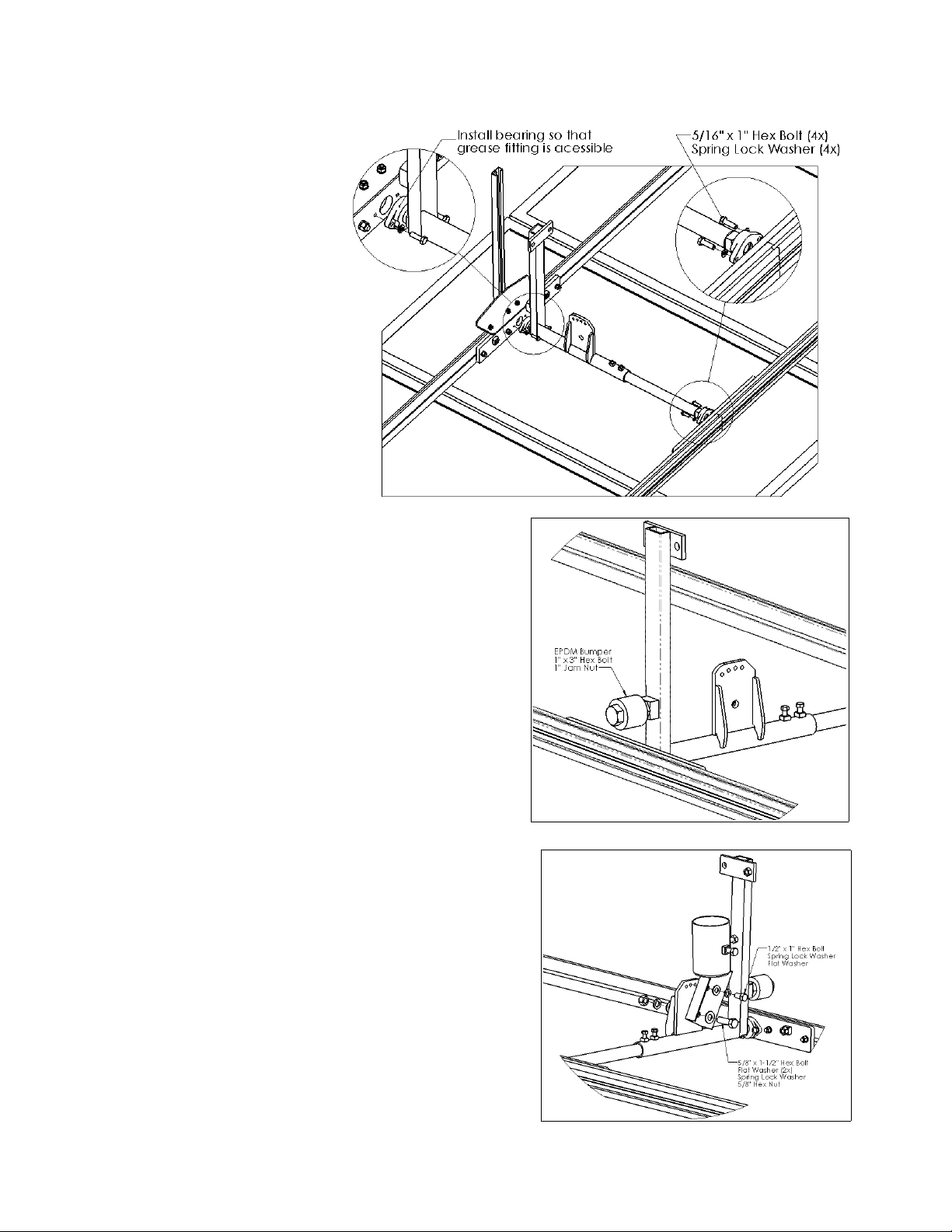
•The North Bearing Plate has two welded-
on square nuts for mounting the shock/s.
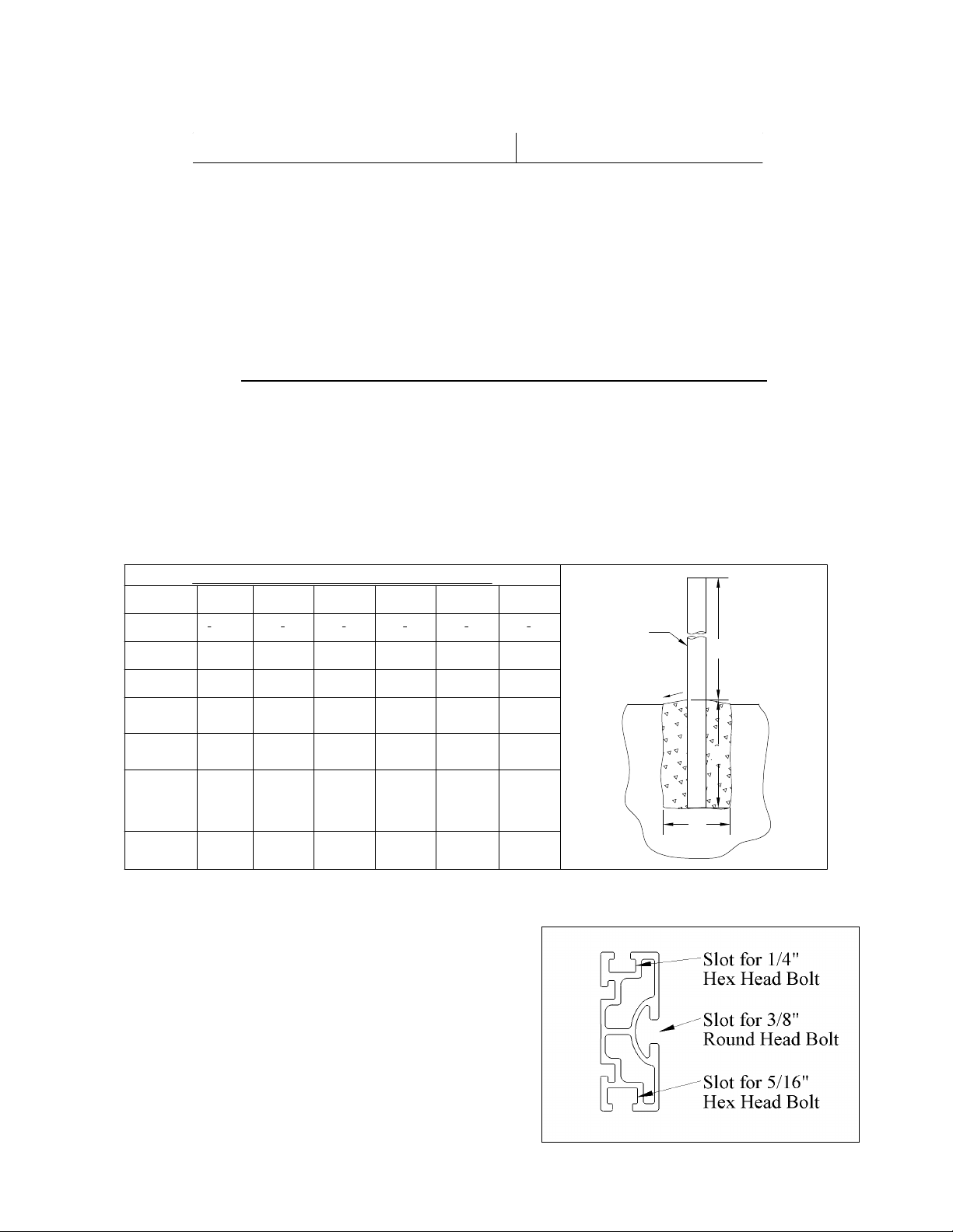
•Orient the Extruded Rail sections so that the
1/4” slot is on the top.
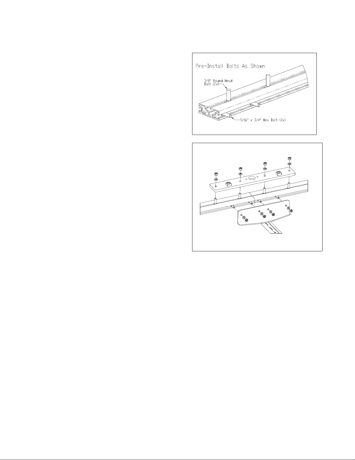
•Pre-install two of the 3/8” x 1-1/4” round
head bolts in each rail section.
•Pre-install two 5/16” x 3/4” hex bolts in each
rail section.
•Adjust the 3/8” bolts as necessary to align
with holes in North Bearing Plate.
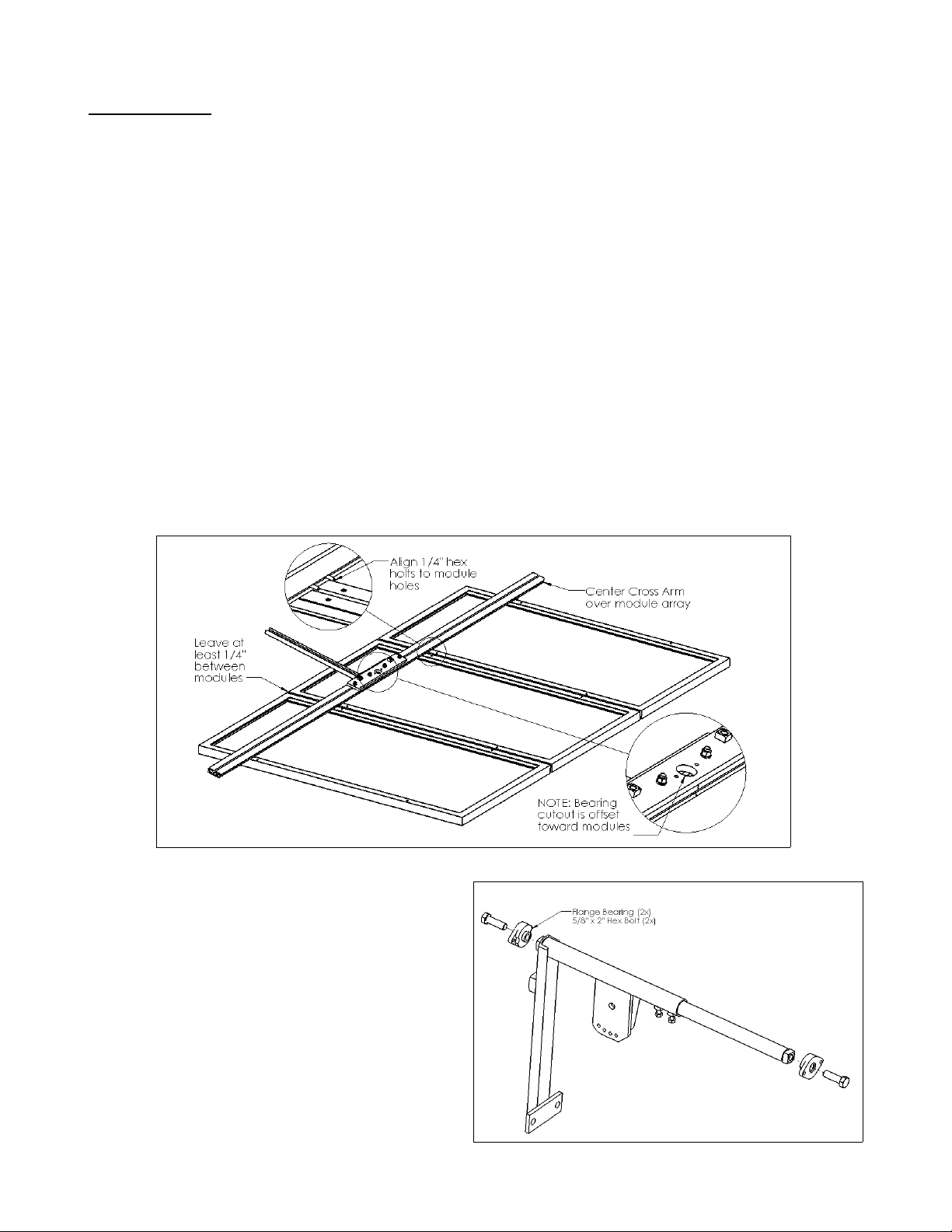
•Cutout for bearing should be closest to the
1/4” slot, the welded nuts should be closest
to the Counterweight Arm.
•Make sure the rail sections are butted
together and close to straight. Install spring
lock washers and nuts and tighten lightly.
•Install the Counterweight Arm in the same
way. Make sure that the arm is close to
centered on the rail sections.
•Install spring lock washers and nuts.
•When the alignment looks good (rails are
butted/centered, and rails make a straight
line), tighten 3/8” nuts to 30 ft-lbs, and 5/16” nuts to 15 ft-lbs.
South Cross Arm Assembly
•The South Bearing Plate does not have weld-on square nuts.
•Assemble similarly to the North Cross Arm.
•Again, make sure the cutout for the bearing is offset closer to the 1/4” slot.
Method #1 or Method #2
At this point there are a couple of ways to proceed:
1) Building the rack from the “pole-up”, one component at a time.
2) Assembling rails, modules, and axle together and lifting on to the pole.
Method 1 eliminates the step of lifting the completed sub-assembly (up to 200 lbs) on to the
pole, but also makes installing / aligning the modules more difficult on the rails.

If there is access to a flat surface (garage / shop floor, saw horses with plywood, etc.),
Method 2 makes the alignment / installation of the modules quite a bit easier. The completed
sub-assembly can then be lifted on to the pole and tightened in place.
Method #1
Attaching Gimbal to Pole
•Place Gimbal on top of pole.
•Orient Gimbal so that the welded channel “leans”
towards true south (adjust for magnetic declination).
•Tighten bolts to 60 ft-lbs torque in turns to insure both
are tight.
Installing Axle
•Install bolts in the order shown.
•For purposes of installation, tilt the axle in
the shallowest position.
•Bolts only need to be lightly tightened for
rack assembly.
•After assembly is completed, tighten the
5/8” bolt to 75 ft-lbs, and the 1/2” seasonal
adjustment bolt to 30 ft-lbs.
Inner Axle
•Install Inner Axle and tighten 3/8” bolts
enough to keep it in place.
•The position of the Inner Axle will need to
be adjusted when installing modules.
Installing Bearings
•Install bearings as shown. Note the mounting
side of the bearings faces outwards.
•While holding the square welded nuts with
either a 1” open-end wrench or adjustable
wrench, tighten 5/8” bolts to approximately 40-
50 ft-lbs.
•The bearings are designed to swivel and may
not look “square” with respect to the axle.

Attaching Cross Arms
•The Cross Arms are bolted to the flange bearings by 5/16” x 1” hex bolts.
•Don't forget the spring lock washers under the bolts!
•If the bearing is turned in its housing, it may be necessary to twist it into alignment in
order to fit the 5/8” bolt head in to the clearance hole in the Bearing Plate.
•Start bolts by hand, and tighten to 9 ft-lbs (108 in-lbs) torque.
•Note the Counterweight Arm and Shock mounting nuts on the North Cross Arm. Both
bearings should be flush with the top of the Cross Arms.
Shock, Bumper Bolt, and Counterweight Installation
•Bolt the upper half of the Shock to the Cross
Arm using the 1/2” x 2” hex bolt and hex nut.
•Do not tighten down on the urethane bushing –
there should be enough play to allow free
movement of Shock eye (approx. 1/16”).
•Attach the lower half of the Shock using the 1/2”
x 2-1/2” hex bolt and hex nuts.
•Using two 3/4” wrenches, tighten the nuts to 40-
50 ft-lbs torque.
•The Bumper Bolt does not need to be tightened
between the head of the bolt and the jam nut.
•Using the 1-1/2” wrench or adjustable
wrench,tighten the Bumper Bolt jam nut against
the welded nut to 75 ft-lbs.
•Install the counterweight as shown. At this point,
the position of the Counterweight is not critical.
Somewhere close to the lower 2/3 of the
adjustment range is a good starting point.

Module Installation
NOTE: Modules must be installed so that they are balanced on the rack. At least 1/4”
space between modules is recommended.
•Make sure that the Axle Assembly is at its shallowest tilt angle, this will make
installation easier.
•Square the Cross Arms as best as you can. Some force is required to swivel the
bearing in its housing.
•Measure the distance between the module mounting holes along the long edge.
•Adjust the spacing of the Cross Arms (by adjusting Inner Axle) so that the centerline
distance of the slots matches the measured distance on the modules.
•Start by pre-installing the provided 1/4” hex bolts in to the slots on the extruded rails (2
bolts on each rail per module).
•Lift module up to the Cross Arms and locate the innermost hex bolt on the North Cross
Arm with the mounting hole on the backside of the module. Install provided flange nut.
•HINT: First lightly tighten the bolt closest to the center of the North Cross Arm.
Next, align the edge of the module so that it is aligned with the centerline of the
rack. Lightly tighten the same-side bolt on the South Cross Arm. At this point,
make any needed adjustments to the alignment or spacing of the Cross Arms. If
done correctly, installing the other modules will be quite a bit easier.
•When the alignment looks good
install remaining bolt / nuts.
•Tighten 1/4” hardware to no
more than 75 in-lbs (6 ft-lbs).

Method #2
Module Layout
•Lay the modules face-down on a flat surface (plywood on sawhorses, shop floor, large
workbench, etc.) as they will be configured on the rack.
•Leave at least 1/4” space between adjacent module edges.
•The outside to outside distance of the module array must be 115” or less. This is
necessary to allow at least 2” between the canister and the outside edge of the
module.
•Pre-install the required number of 1/4” hex bolts in the extruded rail. Make sure to use
the correct slot and check to be sure that the bearing cutout faces towards the inside of
the rack and is offset towards the module (see drawing).
•Carefully arrange the 1/4” bolts so they line up with the module holes.
•Install the Cross Arm on to the row of modules. Install provided flange nuts. Hand
tighten only.
•Repeat this process with the other Cross Arm.
•Check alignment.
•Tighten the flange nuts to no more than 75 in-lbs (6 ft-lbs).
Bearing Installation
•Install bearings as shown. Note the
mounting side of the bearings faces
outwards.
•While holding the square welded nuts
with either a 1” open-end wrench or
adjustable wrench, tighten 5/8” bolts to
approximately 40-50 ft-lbs.
•The bearings are designed to swivel
and may not look “square” with respect
to the axle.

Axle Installation
•Install Axle Assembly as
shown.
•Orient that bearings so
that the grease fitting
can be accessed from
underneath the rack.
•Adjust the length of the
Axle Assembly to fit
between Cross Arms.
•5/16” hex bolts should
be tightened to 9 ft-lbs
(108 in-lbs) torque.
•3/8” axle set bolts can
now be tightened to
approximately 20 ft-lbs.
Bumper Bolt Installation
•The Bumper Bolt does not need to be
tightened between the head of the bolt and the
jam nut.
•Using the 1-1/2” wrench or adjustable
wrench,tighten the Bumper Bolt jam nut
against the welded nut to 75 ft-lbs.
Gimbal Installation
•Install the Gimbal as shown.
•The 5/8” and 1/2” bolts should be lightly
tightened.
•With the Gimbal installed, the rack can now be
lifted on to the mounting pole.
•At this point the rack with modules can weight
up to 200 lbs or more – use caution!
•Orient Gimbal so that the welded channel
“leans” towards true south (adjust for magnetic
declination).
•Tighten set bolts to 60 ft-lbs torque in turns to
insure both are tight.

Shock and Counterweight Installation
•Bolt the upper half of the Shock to the Cross
Arm using the 1/2” x 2” hex bolt and hex nut.
•Do not tighten down on the urethane bushing –
there should be enough play to allow free
movement of Shock eye (approx. 1/16”).
•Attach the lower half of the Shock using the 1/2”
x 2-1/2” hex bolt and hex nuts.
•Using two 3/4” wrenches, tighten the nuts to 40-
50 ft-lbs torque.
•Install the counterweight as shown. At this point,
the position of the Counterweight is not critical.
Somewhere close to the lower 2/3 of the
adjustment range is a good starting point.
End of Method #2 Instructions
Canister Mounting Tabs
•Canister Mounting Tabs are pre-
assembled with the necessary
hardware.
•Two of the tabs are mirrored copies of
the other.
•The strap goes on the top side of the
rack.
•Loosen the hardware a few turns and
install as shown.
•Slide the Mounting Tab on to the
extrusion until the corner of the
chamfered edge is even with the end of
the Extruded Rail.
•Press the Tab firmly against the corner of the Rail and tighten the 3/8” nut to 30 ft-lbs.
•Repeat procedure for all corners.
Canister Installation
•Important Note: Fluid is driven between canisters via 1/4” copper tube. When
removing the Canister Set from the package and when straightening the transfer
tube, be careful to not crimp it. We recommend that at least two people handle
the canisters to prevent any damage.

•Orient the Canister Set so that the unit with the wake-up fin is on the west side of the
rack (with the wake-up fin underneath the rack). The transfer tube is designed to enter
from the bottom (underside) of each canister.
•Remove the 1/4” hex nuts and square washers from the top of the Canister Mounting
Tabs and open up the strap.
•Align the Canister as necessary in order to find a place for the strap clamps. The
Canisters can usually be installed so that they are centered with respect to the Cross
Arms. If the Canisters must be offset, this will not affect the function of the rack.
•Re-install the strap, square washer and 1/4” hex nut.
•Tighten the 1/4” hardware to no more than 75 in-lbs (6 ft-lbs).
•Repeat the procedure for remaining Canister clamps.
Installing Shadow Plates
•Each canister must
have a Shadow Plate.
The plate that has a
Zomeworks sticker can
be installed on either
side of the rack.
•Using the 1/4” round-
head bolts, lock
washers, and wide flat
washers provided,
install as shown.

Balancing and Counterweight Adjustments
•Balancing and set-up is crucial to getting the most out of your Track Rack™
•Start by ensuring that the module rails are installed equidistant from the center axle.
•Pay attention to balance when installing additional components (inverters, wires /
conduit, etc.)
•Track Racks™ will work within a range of
Counterweight adjustments.
•If the tracker is not going through the full travel range,
raise the Counterweight.
•Keeping the Counterweight low will make the tracker
more stable in wind.
•Provided that additional stability is not required for
gusty winds, the optimal Counterweight position results
in the Truss Tube lightly touching the Bumper Bolt at
the beginning and end of the day (when all Freon has
been shifted).
Seasonal Adjustments
•Trackers can be tilted in one position or adjusted seasonally to increase output.
Adjusting tilt throughout the year can add approximately 3-6% to the annual output (will
vary with location, climate, etc).
•If setting the rack for one year-round setting, the tilt should be close to the latitude.
For example: In Albuquerque, NM
(latitude 35.1°N) a tracker
should be tilted close to 35°
(as measured from
horizontal). The Seasonal
Adjustment Plate offers a
position of 35°– this angle will
work well.
•If adjusting the rack throughout the
year, adjust the tilt so that the sun
hits the surface of the modules as
close to a right angle as possible.
•A good compromise is to adjust the
rack to a tilt of latitude + 15°(or
max.) around the fall equinox
(September 22th) and latitude – 15°
(or min.) around the spring equinox
(March 20th).
•After setting the tilt of the rack, tighten the 5/8” pivot bolt to 75 ft-lbs, and the
1/2” bolt to 30 ft-lbs.
COUNTERWEIGHT
POSITION
LOWER
HIGHER
•
MORE STABLE
•
LESS MOVEMENT
•
MORE MOVEMENT
•
(POSSIBLE) FASTER
WAKE-UP
•
MORE EASILY BLOWN
OFF-COURSE
•
"SEARCHING" FOR SUN
•
FULL MOVEMENT WITH
FULL SHIFT OF
REFRIGERANT
•
GOOD STABILITY
•
REASONABLE WAKE-UP
TIMES

Maintenance
•Bearings with grease fittings should be lubricated with a general-purpose bearing
grease twice a year.
•Paint touch-up will be necessary to prevent rusting. Sand off all rust prior to painting.
Use a high-quality enamel or Rustoleum® type paint.
•If the Track Rack™ is installed in a corrosive climate, check the axle and bearings
frequently for rust or corrosion; you may need to grease the bearings 3 to 4 times per
year and keep the axle coated with grease or a corrosion inhibitor.
•Check the Shock bolts, Shock Mounting Arm bolts, and Bumper bolts twice a year and
tighten if necessary. Also check the Axle pivot bolt and Seasonal Adj. Bar bolts. Loose
bolts increase wear on mating parts and introduce the potential for failure.
•Inspect the pivot bolt area of the Axle-Gimbal junction for wear. Signs of excessive
movement may indicate that the bolt has worn down. Another indication of wear is that
the bolt, even when tightened properly, repeatedly comes loose. If this is the case,
replace the bolt.
PROPER MAINTENANCE IS THE RESPONSIBILITY OF THE CUSTOMER!
HIGH WINDS: Trackers should be tied in horizontal position if high-wind events are
anticipated. Tie-down straps or ratchet straps can be used to secure the rack (not provided by
Zomeworks).
EXTREME COLD: In cold weather the fluid in the shocks thickens and can increase wake-up
times. In very cold temperatures (< -10F°), trackers may cease to track. In these conditions
we recommend tying the tracker in a fixed due-south position at the steepest tilt angle.
Tracker Troubleshooting
•TRACKER SITS LEVEL, LEANS TO ONE SIDE, OR DOES NOT MOVE
1. Manually move tracker through its entire range of motion. Check for any mechanical
interference, for example: wiring, tree branches, protruding bolts, etc. and correct if
necessary.
2. Check Shadow Plates for proper installation. The tracker will not work without them.
3. Be sure the Track Rack™ is pointing south (in the Northern Hemisphere) and the
copper transfer tube is mounted on the south (lower) end of the frame, and is not
crimped in any way.
4. Check for any wiring that may stop the Track Rack™ from turning freely. Also check if
wiring and junction boxes, etc. are balanced about center axle.
5. A shock absorber might be sticking. On a calm sunny day remove the shocks at the
Bearing Plate. If it tracks without shocks, call Zomeworks. The shock may be defective.
6. The Track Rack™ moves when sunlight warms one canister which then forces liquid
into the other canister. You may simulate the sunlight's effect by warming the lower
canister with a hair dryer or carefully with a hand torch (alternately, the upper canister
can be cooled with wet towels or water spray). Within 10 minutes the tracker should
begin to rotate toward the cooler canister. If the tracker does not move, and you have
checked the assembly for free movement, the Canisters may have lost their charge.
Call Zomeworks tech support.

•TRACKER IS SLOW TO WAKE UP
1. Check that your tracker is getting full, early morning sun shining underneath the
framework. The wake-up fin (under the west-side canister) must see the sun.
2. Check that modules and electrical components are balanced over the center axle.
3. Check that bearings are lubricated and move easily. NOTE: If the Track Rack™ is
installed in a corrosive climate, check the axle and bearings frequently for rust /
corrosion.
4. The shock/s may be sticking when collapsed or extended. Remove the shock bolt at
the Bearing Plate and check the shock motion for “stick”. If the tracker wakes-up
without the shocks, they may be defective. IMPORTANT: Do not leave the tracker
defenseless without shocks – a strong wind could easily damage it. The rack can
easily be tied down by using customer-supplied tie-downs or ratchet straps.
•TRACKER DOES NOT HIT THE BUMPER STOPS
1. Trackers are very effective even if they don't track all the way to the bumper stop. The
bumper stops are set for approximately 90°of rotation.
2. To increase the amount of rotation, raise the counterweight. NOTE: Raising the
counterweight also makes the tracker slightly less stable in wind. For optimum tracking
and stability, the Cross Arm should be only be resting lightly on the bumper bolt at the
beginning and ending of the day. If the tracker rotates further to one side than the
other, this may indicate that it is imbalanced left to right. This can be fixed by making
small adjustments to the position of the mounting rails / modules.
•GENERAL SUMMARY
1. For proper performance, trackers must be assembled correctly.
2. The Track Rack™ should rotate smoothly throughout the entire range, with the only
drag supplied by the shock absorbers. If friction or interference is noted, check
assembly against instructions and make required corrections.
3. Photovoltaic modules should be mounted as shown in the module layout diagram and
as described in the instructions. Balance is critical!
4. There must be a minimum of 2” from the edge of the solar module to the Canister.
Insufficient space will interfere with tracking.
5. The Track Rack™ must be in a location that maintains a clear line-of-sight to the sun
throughout the day, and during different seasons. Shadows cast in the early-morning
light can significantly delay the wake-up time.
6. If high winds or severe storms are expected, securing the rack in a horizontal position
with straps is the best way to prevent damage.
7. Zomeworks Track Racks™ will move in the wind, much as trees do. This motion
is expected and does not harm the tracker or its performance. Unless a tracker is
blown far off the sun and stays there, the output is hardly affected. Overall, Track
Racks™ far exceed the performance of a fixed array.
For product and purchase inquiries contact:
www.ecodirect.com | 888-899-3509

ZOMEWORKS TRACK RACK™
LIMITED WARRANTY
Zomeworks Corporation guarantees, to the original owner, its Track Rack™ passive solar
tracker and fixed racks against defects in materials and workmanship for TEN YEARS from
date of purchase. Shock absorbers and bearings are warranted against defects in materials
and workmanship for TWO YEARS from date of purchase.
This warranty is limited to the repair or replacement of the Track Rack™ or fixed rack in
compliance with the instructions provided by Zomeworks.
Some problems can be solved with a simple on-site adjustment. Please contact Zomeworks
Corporation at the address and phone number below before returning your product. You must
have an RMA number to return the product for warranty repair. If possible, return only the
parts that are defective or damaged. Reuse your original packing material, if it's available, or
call the factory for further instructions.
IT IS THE OWNER'S RESPONSIBILITY TO CHECK FOR DAMAGED OR MISSING PARTS
IMMEDIATELY UPON RECIEPT OF THE TRACK RACK™ OR FIXED RACK. Freight claims
are time sensitive and require immediate notice. If the packaging is damaged, write this on
the receipt (freight bill) and have the driver initial this. Use this information to contact your
freight carrier when damage is noticed.
Upon receipt of a defective part(s), freight pre-paid, Zomeworks will determine whether the
defect was caused in manufacturing. If so, the part(s) will be repaired or replaced at no
charge to the customer, and will be returned freight pre-paid. If the damage is not a
manufacturing defect, the factory will contact the customer before any repairs are made.
Original owners should contact their dealer if immediate replacement part(s) are needed.
Individuals contacting Zomeworks Corporation desiring immediate replacement part will be
required to provide Zomeworks Corporation with a valid credit card number to be charged for
the replacement part(s). Zomeworks Corporation will credit the valid card upon receipt of the
warranted returned part(s) from the individual.
This warranty does not cover rusting of the steel due to a corrosive environment (such as salt
air). Standard Track Racks™ and fixed racks are painted mild steel and will require
maintenance. It is the owner's responsibility to maintain the paint on the rack in order to
protect the steel against corrosion. For corrosive environments, Zomeworks Corporation can
manufacture the mounting racks with an epoxy primer.
Limitations on Warranty
The above ten-year and two-year warranties are the only warranties and remedies provided
by Zomeworks to user. Zomeworks disclaims all implied warranties of merchantability and
fitness. In no event shall Zomeworks be liable for consequential or incidental losses or
damages under any theory of liability, except to the extent that this limitation is found to be
unenforceable under applicable state law. Some states do not allow the exclusion or limitation
of incidental or consequential damages, so this exclusion may not apply to you. This warranty
gives you specific legal rights, and you may also have other rights that vary from state to
state.
Other manuals for UTR-020 TRACK RACK
1
This manual suits for next models
5
Table of contents
Other ZOMEWORKS Inverter manuals
Popular Inverter manuals by other brands

Omega
Omega OTEC IEWQ-R Series Service manual

Siemens
Siemens SINAMICS V20 Inverter operating instructions

Saurium
Saurium DLGE2500 Operating instruction

Hoymiles
Hoymiles HM-1500 Quick installation guide

Bosch
Bosch mm-Si plus EU1510 Series Planning and installation instructions

Bergey
Bergey POWERSYNC II Series Operator's manual & installation instructions