»Zone Oroad Products • 491 W. Gareld Ave., Coldwater, MI 49036 • 888.998.ZONE • www.zoneoroad.com
Read and understand all instructions and warnings prior to installation of product
and operation of vehicle.
Zone Oroad Products recommends this system be installed by a professional technician. In addition to these instructions, profes-
sional knowledge of disassembly/ reassembly procedures and post installation checks must be known. Minimum tool requirements
include the following: Assorted metric and standard wrenches, hammer, hydraulic oor jack and a set of jack stands. See the "Special
Tools Required" section for additional tools needed to complete this installation properly and safely.
»Product Safety Warning
Certain Zone Suspension Products are intended to improve o-road performance. Modifying your vehicle for o-road use may result
in the vehicle handling dierently than a factory equipped vehicle. Extreme care must be used to prevent loss of control or vehicle
rollover. Failure to drive your modied vehicle safely may result in serious injury or death. Zone Oroad Products does not recom-
mend the combined use of suspension lifts, body lifts, or other lifting devices.
You should never operate your modied vehicle under the inuence of alcohol or drugs. Always drive your modied vehicle at re-
duced speeds to ensure your ability to control your vehicle under all driving conditions. Always wear your seat belt.
»technical SuPPort
www.zoneoroad.com
may have additional information about this product including the
latest instructions, videos, photos, etc.
Send an e-mail to
detailing your issue for a quick response.
888.998.ZONE
Call to speak directly with Zone tech support.
»Pre-inStallation noteS
1. Special literature required: OE Service Manual for model/year of vehicle. Refer to
manual for proper disassembly/reassembly procedures of OE and related compo-
nents.
2. Adhere to recommendations when replacement fasteners, retainers and keep-
ers are called out in the OE manual.
3. Larger rim and tire combinations may increase leverage on suspension, steering,
and related components. When selecting combinations larger than OE, consider
the additional stress you could be inducing on the OE and related components.
4. Post suspension system vehicles may experience drive line vibrations. Angles may require tuning, slider on shaft may require
replacement, shafts may need to be lengthened or trued, and U-joints may need to be replaced.
5. Secure and properly block vehicle prior to installation of Zone Oroad Products. Always wear safety glasses when using power
tools.
6. If installation is to be performed without a hoist, Zone Oroad Products recommends rear alterations rst.
7. Due to payload options and initial ride height variances, the amount of lift is a base gure. Final ride height dimensions may vary
in accordance to original vehicle attitude. Always measure the attitude prior to beginning installation.
rev032020
F2302 Installation Instructions
2021 Ford Bronco
Adventure Series Upper Control Arm
Difficulty Level
easy 1 2 3 4 5 dicult
Estimated installation: 2-3 hours
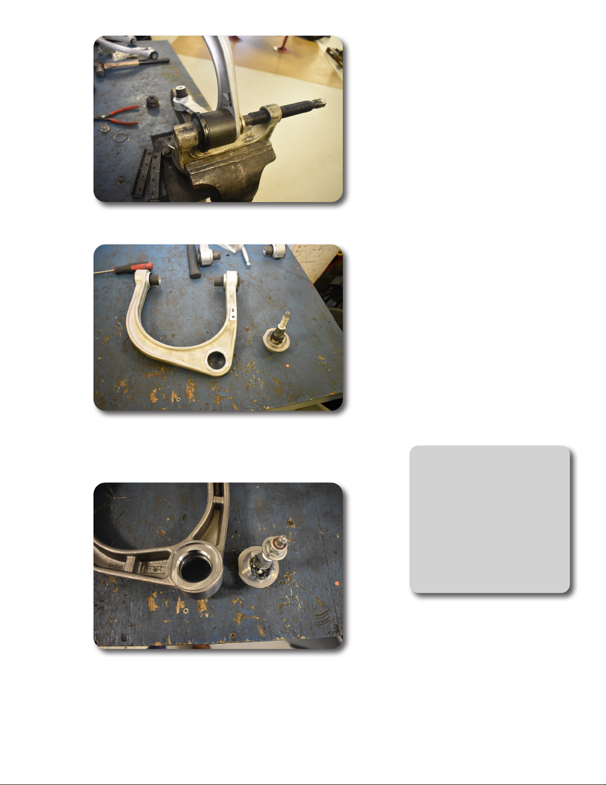
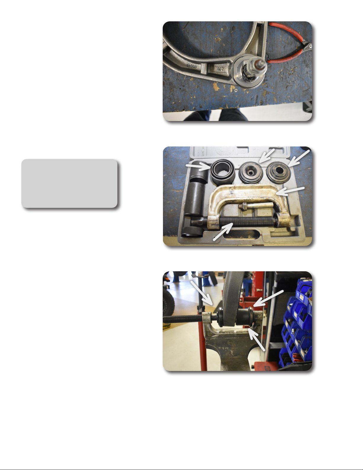
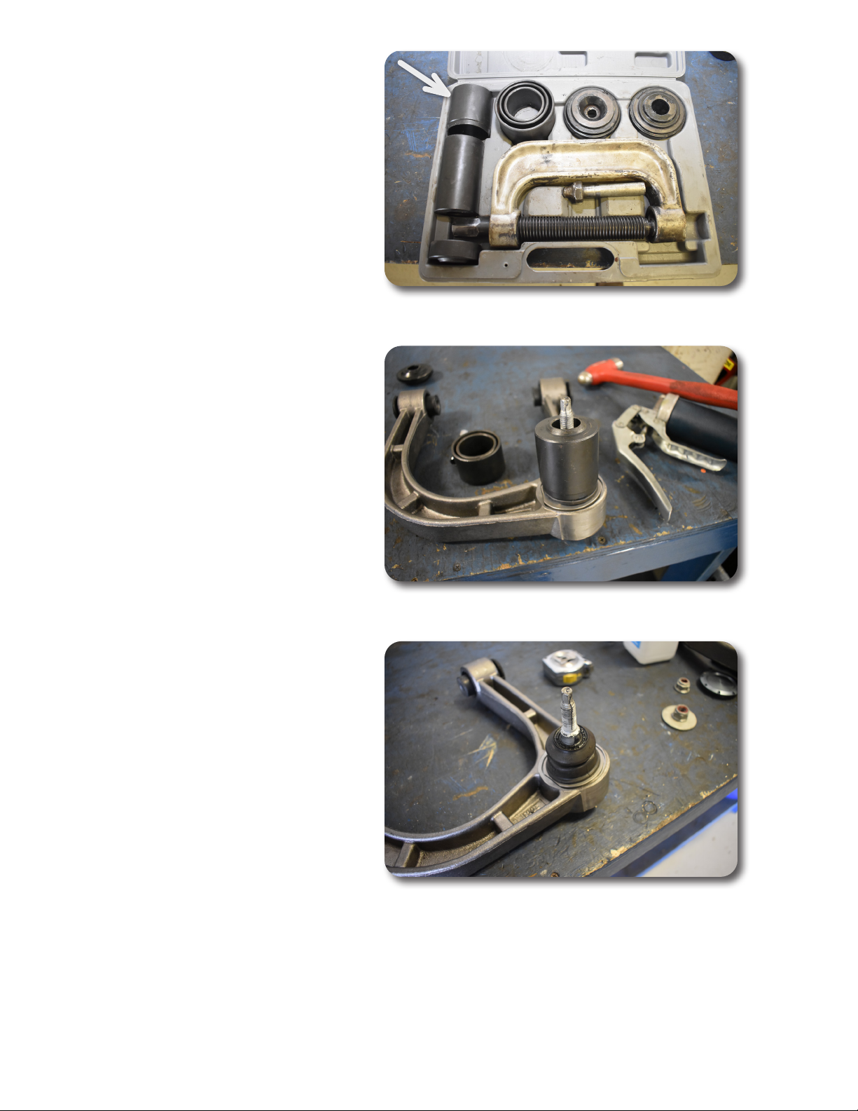
Special Tools Required
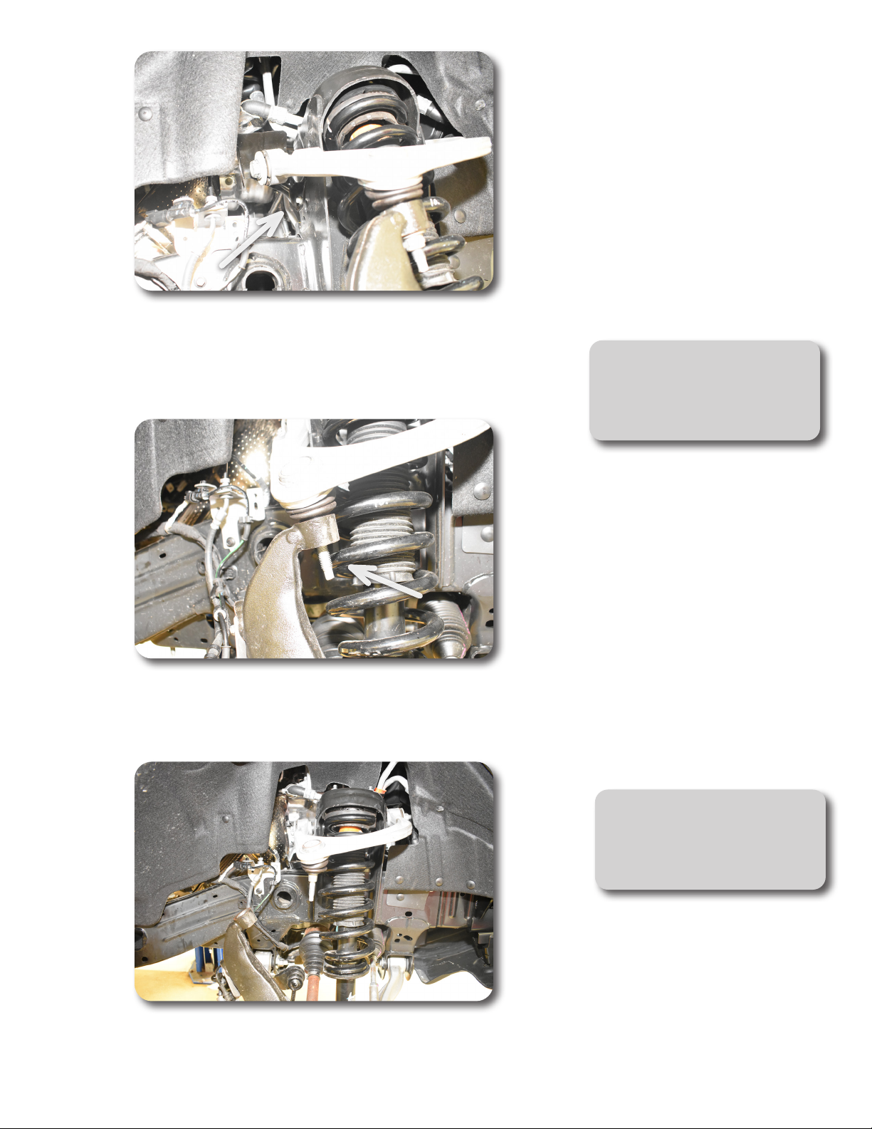
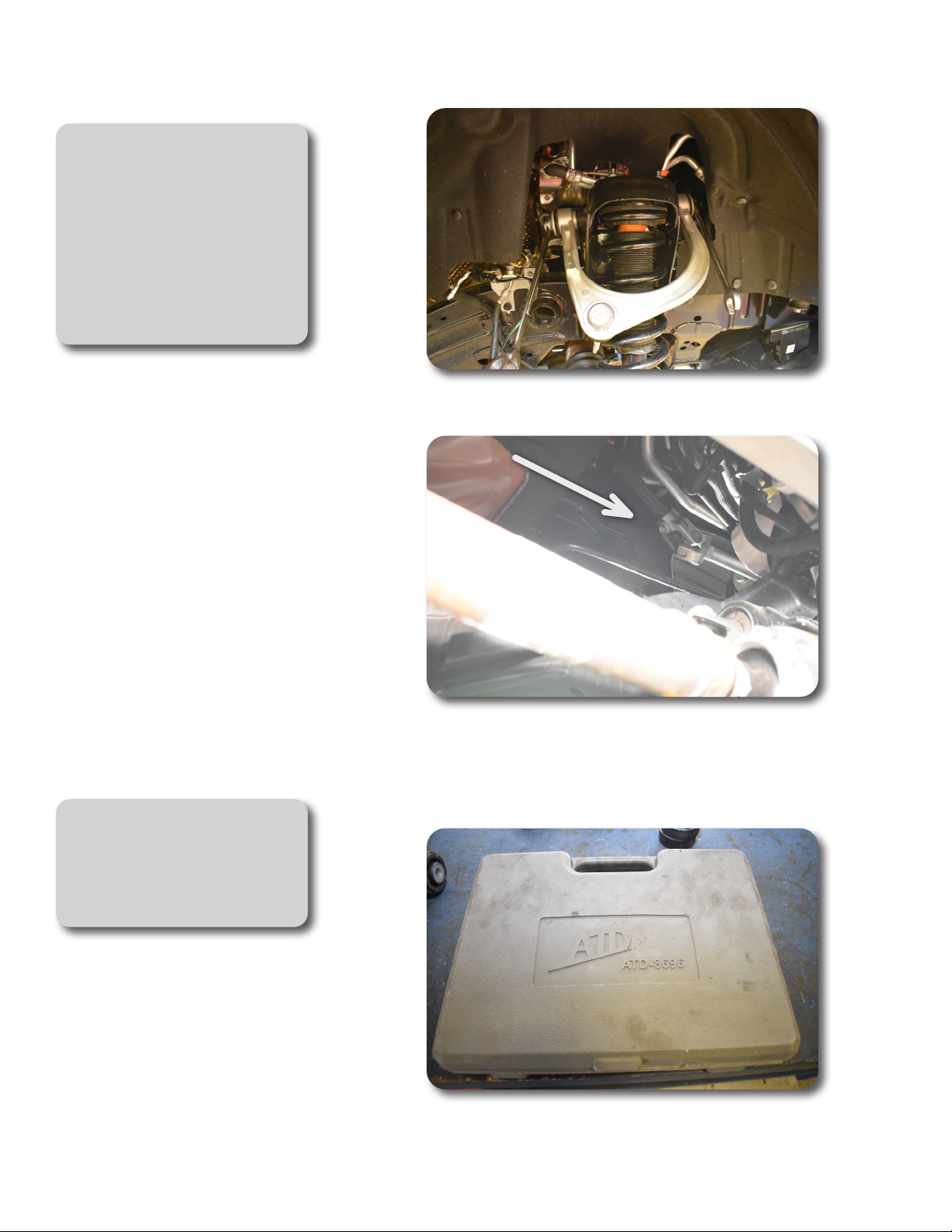
OTC 204-592 Ball Joint Separator
ATD 8696 Ball Joint Press
Tire/Wheel Fitment
Stock wheels and stock tires can be
installed. Taller tires on stock wheels
may contact the UCA. 4.5" to 5" back
spacing wheels is recommended for
most clearance to the UCA. 5.5" back
spacing on a 35" tire will be close to the
UCA at full steering lock.