Zone Spark User manual

User’s Guide
Zone Spark
Neighborhood Electric Vehicle
and 6-Passenger Low Speed Vehicle

2
Thank you for your purchase. This guide provides operational and maintenance
information to maximize your enjoyment.
Index
I. Overview………………………………………………………2
II. Safe Operation Instructions …………………………………...3
III. Technical Data ………………………………………………...4
IV. Controls ………………………………………………….........4
V. Operation ……………………………..……………………….8
VI. Maintenance ……………………………………….………….9
VII. Storage………………………………………………………..13
VIII. Frequently Asked Questions………………………………….13
IX. Reset Algorithm for Charger…………………………………15
X. Trouble Shooting Charts and Guides…………………………17
I. OVERVIEW
The low speed vehicle is environment-friendly and suitable for use on qualified
streets (up to 35 mph). It can be used on a golf course, or as a people mover/utility
car in vacation villages, villa areas, resort hotels, private residential areas, tourist
scenic spots, or any other place where this type of vehicle is allowed.
WARNING!
The Zone Spark meets FMVSS 500.517 (Federal Motor Vehicle Safety Standards
for Low Speed Vehicles). Please learn whether there are any restrictions in the
area where you intend to use the vehicle. Contact your local DEPARTMENT OF
MOTOR VEHICLES for any information on compliance requirements for
licensing. All low speed Neighborhood Electric Vehicles are subject to federal
guidelines as well as local state law.

3
II. SAFE OPERATION INSTRUCTIONS
The low speed vehicle is designed for a simple operation; however, please make sure
to observe the following safe operation instructions:
BEFORE OPERATING THE VEHICLE:
●ALWAYS read this first before you start driving the vehicle.
●ONLY authorized people should drive this vehicle, from the driver’s side ONLY.
●Drive the vehicle ONLY in areas where the vehicle is allowed by law or local
regulations and the conditions are safe to do so.
●DO NOT allow more people on the vehicle than the vehicles’ designed capacity.
●DO NOT overload the vehicle, otherwise, the motor may get damaged, and the
vehicle may lose control, putting the driver and passengers in danger.
●DO NOT operate the vehicle while under the influence of alcohol or drugs.
●DO NOT make the vehicle climb any slope beyond its grade ability.
●DO NOT overtake other vehicles at crossroads, in blind areas, or in any
dangerous areas.
●CHECK WITH YOUR LOCAL GOVERNING AUTHORITIES to ensure that
you remain in compliance with any laws, rules or regulations regarding the
operation of a Low Speed Vehicle. The Zone Spark meets FMVSS 500.517
(Federal Motor Vehicle Safety Standards for Low Speed Vehicles).
WHILE OPERATING THE VEHICLE:
●Keep your entire body inside the vehicle, remain seated, buckle up with the seat
belts, and hold on while the vehicle is moving.
●Do not start the vehicle until all occupants are securely seated and fastened set
belts.
●Keep your hand on the steering wheel and your eyes on the path or road you are
travelling.
●Always back up slowly and watch behind you carefully. Vehicle does make a
beeping noise while in reverse.

4
●Avoid starting or stopping suddenly.
●Avoid turning the steering wheel too sharply at high speeds.
●Always drive slowly up or down inclines. Do not make any modifications or
additions to the suspension which may affect the capacity or safety of the vehicle.
●Children should not be allowed to play in the car. Children should be seated
between adults and protected by them while the car is moving.
III. TECHNICAL DATA
IV. CONTROLS
Locate the controls on your vehicle before driving. Familiarize yourself with their
locations and functions. The pictures below give a general location and description of
major components. After the pictures, additional details are provided for each of the
controls.

5

6
FUNCTION OF CONTROLS:
KEY SWITCH
The power key switches on the vehicle’s electrical system. To engage the motor
and drive the car, insert the key and turn clockwise to the “On”position. The
switch engages the 12v accessory system (headlights, horn, radio, turn signals) at
the same time. The parking brake lights will remain illuminated while the key is
on and brake system is in the lock position.
FORWARD AND REVERSE SELECTOR
This selector is a three-position switch; depressing the upper part activates the
forward direction of the vehicle, pressing the lower part activates reverse, and the
middle position is neutral.

7
WARNING! Switch must be fully depressed into the proper position.
DO NOT shift from Forward to Reverse until the vehicle has come to a complete
stop.
Note: While in reverse, a beeping noise occurs.
STATE OF CHARGE METER
There are 10 divisions in this meter from 0 –1. This meter will descend from the
top (1) to the bottom (0) as the battery discharges. When the battery pack is too
low, the bottom two indicator lights will flash. For best performance, recharge
your car when the battery pack is roughly three quarter of capacity or any
opportunity possible to do a surface charge.
TURN SIGNALS/HORN SWITCH
This switch is used to turn on/off the turn signals. Move handle lever upward to
switch on the right signal, move handle lever down to switch on the left signal.
The signals are not self cancelling. Gently pulling the handle towards the driver
sounds the horn.
HEADLIGHT SWITCH
Attached to the column control unit, on the lower right side is a small push/pull
button. Pull button out to turn on the head and tail lights. Push button into the
column turns off the lights.
ACCELERATOR PEDAL
The accelerator pedal is used to control the speed of the vehicle. Press pedal down
slowly to increase the speed. The car will speed up with the gradual depression of
the pedal, eventually reaching full speed when the pedal is pressed down to the
floor completely. The vehicle will slow down with the lifting of the pedal. When
the pedal is fully lifted, the electric brake will function and aid in slowing the car
to a stop.
WARNING! The electric brake is not a substitute for the parking brake.
SERVICE BRAKE/PARKING BRAKE
The brake pedal is used in deceleration and stopping. The effective braking force
is around 66 foot pounds. The distance of travel of the pedal should not exceed
2/3 of overall distance.
The effective parking force is around 44 foot pounds. To activate the parking
brake, press the foot pedal on the top ¼ until an audible clicking sound is heard.
The park brake should be used any time the vehicle is left unattended.
NOTE: If the park brake fails to lock, please repeat above procedure until it fully
engages.

8
WARNING! It is prohibited to step down on both the brake pedal and the
accelerator pedal at the same time. This can cause severe damage to the motor
and/or controller.
WARNING! The parking brake will automatically release when the accelerator
pedal is depressed. If the key switch is in the “ON”position, depressing the
accelerator may cause the vehicle to abruptly move. Disengage the brake before
activation of vehicle.
CHARGING SYSTEM
The charging system on this vehicle is located at the rearmost of the car under the
rear seat. The charger is either a DELTA-Q or an ELCON brand charger. The on-
board charger units are fully sealed and enclosed by a rear cover. The charge port
to plug the vehicle in is located on the passenger or driver side of the car just
above the floorboard. Charge status indicators are located next to the ports and are
as follows:
a) DELTA-Q. The indicator will display a quick flashing green light during
the bulk of the charge cycle. Once the batteries reach 80% of capacity, the
light will display a slowly flashing green light. Once the batteries are
fully charged, the LED will be solid green.
b) ELCON. The round indicator will display a flashing red light during the
bulk of the charge cycle. Once the batteries reach 80% of capacity, the
light will flash amber. Once the batteries are fully charged the light will
flash a steady green.
RUN/TOW SWITCH
The purpose of switch is to disengage the electrical system from the battery pack.
In the event you have to push or tow the vehicle outside of its own power, you
must place it in the TOW position. If you do not, the anti-roll away feature will
energize and slow the vehicle down. This can damage the controller or motor if
left in RUN and vehicle is towed.
The secondary use for this switch is for storage. By placing the vehicle in the
TOW position and removing the electronics from the battery pack, it will greatly
reduce the parasitic voltage draw and keep your batteries from losing charge as
fast.
V. OPERATION
Starting your vehicle:
a) Depress brake pedal or accelerator pedal gently to remove parking brake. Keep
brake applied.
b) Turn the vehicle key clockwise to the “ON”position.
WARNING! Do not step on accelerator pedal when turning on the power key,
otherwise, the vehicle may suddenly start to move.
c) Select desired direction of travel.

9
d) Check that your path is clear in the direction you will be going, remove pressure
from brake pedal and slowly press down on the accelerator.
Stopping your vehicle:
a) To stop the vehicle, release the accelerator, gradually press down on the brake
pedal.
b) When the vehicle comes to a complete stop, apply the parking brake.
c) Place car in the neutral position.
d) Turn key counter-clockwise to the off position.
VI. MAINTENANCE
User should perform regular maintenance on vehicle to ensure good performance.
BATTERY MAINTENANCE:
WARNING! Battery electrolyte is poisonous and dangerous; the acid can cause
severe burns. Battery gasses are flammable and explosive. Keep away from open
flames at all times. Always wear protective clothing, gloves, and goggles when
handling batteries. KEEP OUT OF REACH OF CHILDREN.
a) Cleaning of Batteries:
The exterior of the battery, the battery connections and battery cables, should always
be cleaned of any acidic corrosion. The battery compartment should be checked and
cleaned once every 2-4 weeks. To clean the battery, place vehicle in wash area, place
the vehicle in the TOW position, make sure the battery caps are tight, and use a
common garden hose. If corrosion persists or has gone unattended and has gotten bad,
special attention must be used in cleaning. Using a gallon jug, place 3TBS of baking
soda and 1tsp of dish soap into jug and fill with warm/hot water. Dump over all
batteries and let soak for 5-10 min. rinse off with water hose.
WARNING! Although the electronic components are covered, do not use high
pressure or direct spray to anything other than the batteries. Wait 10 min for car to
dry before driving.
b) Checking Terminals and Nuts:
The connection of the cable and battery should be kept tight at all times (about 70
inch pounds) and in good condition. Every time you check the water levels on the
batteries, you should check the tightness of the cables to prevent spark or damage to
battery post. Any cables that look corroded or damaged should be replaced
immediately.
c) Recharging
The vehicle has a high capacity, flooded lead acid battery bank installed in it. These
deep cycle batteries are not like the ones you will find in an automobile. A deep cycle
battery should be run to 50% of its charge capacity before charging. This will ensure

10
that all of the useful plates inside the batteries are utilized and will limit premature
failures. There is no harm in charging the vehicle as necessary to gain a full charge. It
is in fact recommended that you give the vehicle an opportunity charge whenever it is
not in use. The on-board chargers that come equipped on the vehicles are self
contained and fully automatic. The initial 20 charge cycles will equalize and “mature”
the pack to optimize their performance. During this time, the batteries may take extra
time to charge, (up to 16 hrs). After they reach their maturity, average charge time is
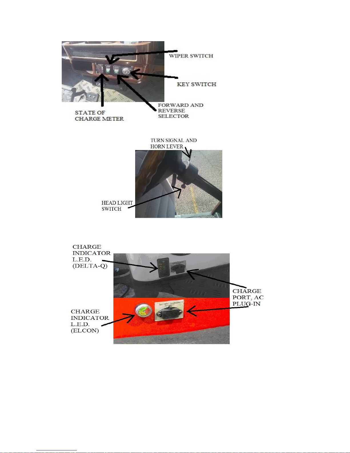
18-12 hrs. Once the batteries have reached their full capacity, the State Of Charge
meter on the dash will reset to indicate a full charge.
If the car is going to remain unattended for up to two weeks, turn the Tow/Run switch
to the Tow position and disconnect the charger. If the vehicle is to be stored over two
weeks, turn the Tow/Run switch to the Tow position and leave the charger plugged
into the car. The smart charger will monitor and maintain a static float voltage during
this time. When the vehicle is ready to be put back into service, unplug the charger
and plug it back in to ensure the maximum charge is given to the battery pack. Place
vehicle in run mode.
d) Watering
After the batteries have had a chance to receive a full charge is the only time you
should adjust the water levels. If you should notice that the plate is exposed prior to
charging, add just enough to cover the plate, then add appropriate amount after full
charge. Only distilled or pure water should be used to fill cells. Tap water contains
trace minerals that can plug the pores on the lead plate. The water levels of the battery
should ONLY cover the plate by ¼ to ½ of an inch. Do not fill battery water so the
level reaches the molded neck of the cell. The battery needs to be able to vent the
gases caused by charging; overfilling of the battery can cause the electrolyte to
overflow. This will reduce the amount of acid in the battery cell and can lead to
premature failure. If any acid is settling on the top of the battery, using a garden hose
as directed in battery cleaning will neutralize it and keep the battery from corroding.
Never add pure acid to a battery.
WARNING! Electrolyte is a solution of acid and water; avoid any contact with skin
and eyes. Wash any affected area with soap and water immediately after contact.
Flush eyes with water for 15 minutes. If irritation persists contact your local
physician.
e) Testing
Two types of tests to obtain a good indication of the battery charge level are the
Specific Gravity reading and an Open-Circuit Voltage reading. Seek a technician for
guidance. Any other type of tests should be conducted by a trained technician with
the appropriate tools.
The factory recommended gravity of a fully charged lead acid battery should read
1.277. The open circuit voltage of a fully charged lead acid battery should read 6.37v
or 50.93v for the full pack. (See Chart)

11
f) Battery Charging
WARNING! Before charging the vehicle, please read any and all information
provided with the charge unit.
WARNING! Explosive hydrogen gas is produced while batteries are charging. Keep
vehicle away from any open flames. Optimal ventilation for vehicle charging is in a
building that can recycle the air 5 times per hour.
WARNING! Before charging vehicle, make sure the AC outlet is capable of handling
20amps of constant draw. Contact your local electrician for verification of load
capacity. DO NOT charge more than one vehicle at a time on a single breaker.
The key must be in the “off position to charge. Plug AC cord into vehicle charge
receptacle first, then plug into wall outlet. Let the charger run until it reaches full
charge. Remove cord from wall outlet then remove cord from the vehicles charge
receptacle. Charger unit is fully sealed. Under no circumstances should you try to
open the charger case. Failure of the charger unit MUST be repaired by an authorized
dealer. Any tampering of the charger unit will void its warranty.
MAINTENANCE of the SEP-EX MOTOR:
Periodic Inspection of the motor will ensure a long life. Before doing any work on or
around motor, Tow/Run switch should be placed in the Tow position. Keep motor
clean from dust, dirt, and any fine debris that collect on/around it. Low pressure air
(20-30psi) works best for cleaning. Every 3-4 months use low pressure air to blow
any dust and carbon from brush area at the end of the motor. The brushes are located
under a metal ring that wraps the circumference of the motor at the end furthest from
the mounting point to the transaxle. After blowing any debris from motor, check the 4
motor cables for correct torque. Any other service required for sep-ex motor must be
performed by certified technician.

12
MAINTENANCE of the CURTIS 1268 MODEL CONTROLLER:
WARNING! There are no user serviceable parts inside the controller. No attempt
should be made to open, repair or otherwise modify the controller. Doing so may
damage the controller and will void the warranty.
The controller equipped on this vehicle is a model 1268 CURTIS separately exited
motor controller. This controller has a self-diagnostic program built in. It will monitor
and oversee operation of your vehicle while you drive and while it is parked. If at any
time your vehicle fails to respond to your control, the controller may aid in the
troubleshooting of the fault. The controller is covered with all the vehicles
electronics. DO NOT spray high pressure air or water directly at any of the
components.
The controller uses an internal capacitor to maintain its service program and monitor
feature. This means a constant battery draw; though it is very low amp, if the vehicle
is to remain unused for more than 1-2 weeks, ALWAYS turn the Tow/Run switch to
the Tow position.
GENERAL MAINTENANCE
As the new owner of an electric vehicle, constant care and maintenance will give you
many years of continual use. Certain tools may be required for periodic maintenance
and they are readily available at most hardware or auto parts stores.
a) Tire pressure: The 10 inch aluminum wheels equipped on the car requires 25psi at
all times.
b) Grease: There are four (4) grease points on the vehicle; One on each steering
spindle, one on the rack and pinion and one on the steering middle shaft. Use of a
grease gun will be required for maintaining.
c) Rear End: The vehicle has a Direct Helical Drive Transaxle. It is a splash lube
system with built in ventilation. The drain plug on the bottom cover is also used
for filling the unit. From total empty, the axle should take 8-12 ounces of a 90
weight gear lube.
d) Batteries: Special care should be taken with the battery pack in this vehicle.
Constant cleaning of the battery set will NOT cause damage. It is best to keep
them as clean as possible at all times. Battery water should be checked constantly
until you find out how your batteries consume and dissipate water. NEVER let
your batteries run on low or no water. Damage will be caused immediately to
exposed cell plates.
e) Electronics: Battery cables, motor wires, contact and controller wires, and any plug
connections should be checked for proper torque (70 inch pounds) and tightness
once a month. The Tow switch should be engaged during any check of electric
connections.

13
Scheduled maintenance of your new vehicle should be done by a certified technician.
Once per year (or once every 6 months, depending on use) the vehicle should be
checked for brake wear and proper function. Brakes less than 25% of useful pad
(1.2mm) should be replaced immediately. Front wheel bearings should be pulled and
inspected, then if all is good, re-packed and re-installed. The differential pan should
be dropped so it can be cleaned and refilled with fresh gear oil. The tires should be
checked and rotated, straight front to back swap. The structural integrity should be
inspected, all bolts tight at all points of the car. A full battery load test should be done
if available to check useful life of the battery pack.
VII. STORAGE
The battery charger has a built in monitor and “float” feature. If your vehicle is to be
stored for a period of time longer than two weeks, it is recommended that the charger
remain plugged in to maintain full battery voltage. If this is not an option, it is
required to fully charge the batteries at a minimum of once per month. This will
ensure the electrolyte in your batteries will remain at a high freezing point.
Electrolyte of a 30% charged battery will freeze and destroy the battery at 0 degrees
F. The steps listed below should be followed any time you plan on leaving the vehicle
un-attended.
1) Park vehicle in a dry, safe, and well ventilated place. A breathable cover would be
optimal if you have one.
2) Turn the key to the off position and store key in a safe place.
3) Move the tow/run switch to the TOW position.
4) Check the tire pressure to make sure 25 psi is present.
5) Charge the car the night before it is to be unattended.
6) Check battery water level after the car has received an overnight charge.
WARNING! The battery water level should only be checked and added after a full
charge.
VIII. FREQUENTLY ASKED QUESTIONS
Q: I left my car on charge overnight, why is it still not charged?
A: During the first 20 charge cycles, the batteries will go through a “maturing”
process. Charge time can take 16 hours depending on the depth of discharge.
Q: My car charged for 5 hours, why does the dash meter still show a low charge?
A: The state of charge meter will not reset until the vehicle has received a full
capacity charge.
Q: I plug my car in to charge, why do the LED’s flash and change color?

14
A: Colored LED flashes are indications of the state of charge. Refer to charger
section of this manual for details of LED color definitions.
Q: Why does my car ride very rough?
A: This vehicle is based off a golf car chassis. The shock absorbers are only used for
stability. At higher speeds, the vehicle may feel loose or bouncy. The tires on this
car may have also developed flat spot from any length of time being stored.
Q: What size breaker should I use to charge my car?
A: A 20 amp dedicated outlet is recommended; if any other appliance is used on the
same circuit, use a 30 amp. GFI outlets are ok to use. Any questions regarding
upgrades or sufficient power should be directed to your electric company or a
qualified electrician.
Q: How do I turn on the headlights?
A: On the column mounted combo switch, bottom right side, a push pull button is
used to activate the lights.
Q: What type of water do I add to the batteries?
A: Distilled only. Add water to the batteries as needed and only after a full charge.
Q: Can I add battery acid or other additives to the batteries?
A: No. The batteries have porous plates that will collect foreign objects and degrade
the usefulness. Anything other than distilled water should not be added except by
a qualified battery professional.
Q: My car is equipped with a battery life saver. How do I use it?
A: The battery tender is a pulse de-sulfater. It should be left in the On position at all
times except when the car will remain idle or unused for longer than 2 weeks.
Q: Why does my radio have static?
A: The antenna is located under the dash and can cause interference. Moving the
antenna or relocating it to a different point on the vehicle will solve this problem.
Q: How can I get the best life and performance out of my batteries?
A: A battery life saver and battery watering kit gives ease to maintenance and added
life to your battery pack.
Q: I have a short range per charge on my car, what can I do?
A: Check for any loose cables. Cycling batteries will create heat that will naturally
soften the lead. Constant battery maintenance is a must. Refer to maintenance
section for instructions. Battery pack may need a charging algorithm adjustment.
Q: Why does the amber light flash on my Delta-Q charger mean?

15
A: The amber light denotes an internal temp to high for normal. The charge unit then
reduces its output power until temperature is maintained. Ambient air over 85
degrees may cause the unit to be warmer than usual and is not a failure. In some
cases it may be required to check the charge algorithm and adjust as necessary.
Note: Contact manufacturer of the charger for specific information on what
algorithm to use with the battery choice you’ve made.
IX. Reset Alogorithm for Chargers
If the battery pack at any time is replaced, contact the manufacturer of your
charger (Delta Q or El Con) to obtain the correct algorithm setting to reset the charger
for the new battery pack purchased.
Listed below are steps to adjust the charger from a normal 215 amp/hour, flooded
lead-acid battery, to the US250 HC/XC battery with 283 amp hours.
1. How to Reset Algorithm for Delta Q Charger
Remove positive cables from the batteries- passenger side. (Big black cable with red
shrink wrap.) Also remove small 12 gauge-ish RED wire.
NOTE: Make sure you are near a charging receptacle. Vehicle must be plugged in for
procedure.
a. Locate LEDs on charger itself. Specifically looking for ¾ full battery. The battery
will flash current algorithm in system. If you have trouble getting to your charge
unit, you can also use the LED mounted on the body.
b. Once located, plug AC cord into car and into outlet as if charging. Lights on LED
will flash in sequence, letting you know current algorithm.
c. As soon as the ¾ full battery starts to flash on the charger, or the LED on the
body, place small 12 gauge-ish RED wire directly to the positive post and hold for
exactly 3 seconds.
d. Remove wire.
e. Now the ¾ battery LED on the charger or body should flash the next algorithm.
f. Repeat steps c and d until the battery LED flashes 7 times.
g. Once 7th algorithm is reached, hold the RED charge cable (12 gauge-ish wire) to
the positive post for 10 seconds. This saves the current algorithm. You will hear a
faint click coming from the charger and the bar graph LED will flash and start to
light up.
h. Unplug AC cord from car.
i. Unhook red cable from positive post.
j. Wait 10 seconds.
k. Hook positive cables back up to the battery.
l. Ensure correct torque is applied (70-90 inch pounds or 8-9 foot pounds).

16
2. Setting Algorithm for ElCon Charger
NOTE: Make sure you are near a charging receptacle. Vehicle must be plugged in for
procedure.
a. Loosen charger from the rear compartment beneath the rear facing seat.
b. On bottom side of charger, driver side, look for black sticker that says “48
VOLT”. Remove to expose black button.
c. Press and hold button and connect car to the AC outlet (plug in car). Keep finger
on button.
d. LED on charger will flash….when it flashes 6 times, remove finger from the
button.
e. Disconnect AC Power –remount charger to finish procedure.
Note: This corrects the minimal boiling of the batteries, extended charge times, and
thermal cutbacks on charging system.

17
X. Troubleshooting Charts and Guides
Cont.- - -

18

19

20
Table of contents