Zonecheck 450 User manual

ZC450-IB-09/13-01 US
Instruction Booklet
Zonecheck 450


Zonecheck® 450
Copyright
This instruction booklet is property of Project Fire Products Ltd and must not be used or copied without
its written permission.
Information
While every effort has been made to ensure that the information contained within this document is
correct, Project Fire makes no guarantee for completeness or accuracy. Project Fire Products Ltd reserves
the right to change product specifications, designs and standard equipment without notice and without
incurring obligation.
Zonecheck is a registered product name of Project Fire Products Ltd. European patent No. 0907833.


Contents
01 Pre-checks
02 Installation
03 Commissioning
04 Testing
05 Orientation
06 Typical connection
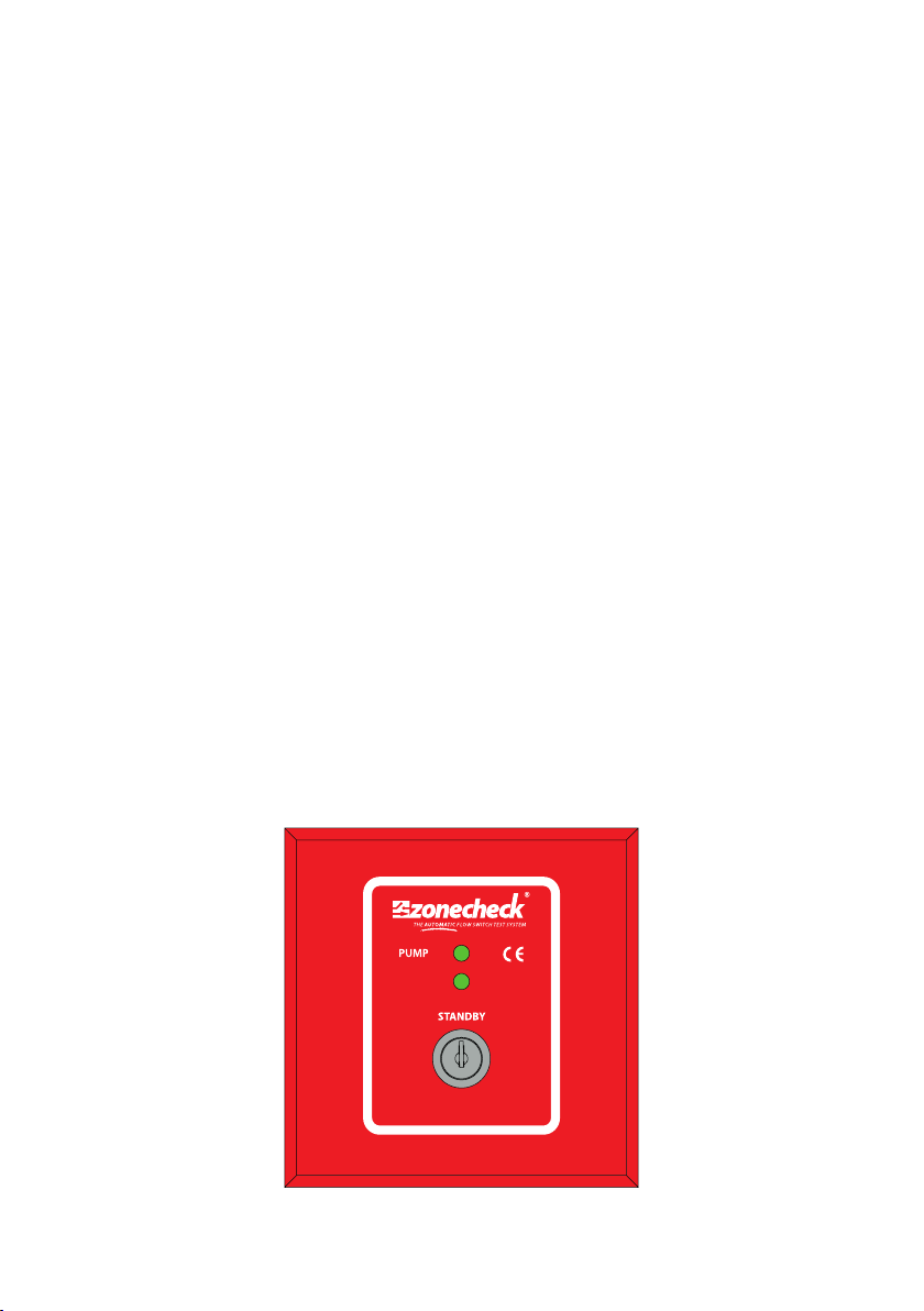
07 Key-switch
08 Wiring
09 Dimensions
10 Specification
11 Troubleshooting
12 Important information
13 Warranty
Pre-checks
Before you install Zonecheck follow these simple steps.
1. Open the box and remove all packaging
2. Check you have the correct size manifold
3. Check that you have the correct model for your site (right or left handed).
4. Check that there is a key-switch and key in the box.
5. Inspect the product to make sure it hasn’t been tampered with. If you have any
queries please contact your supplier.
01
View from above
Left handed
View from above
Right handed

02
Installation
Zonecheck should be installed by a competent fire sprinkler installer and wired up by a qualified electrician.
1. Contact building management to inform them of the proposed works.
2. Isolate and drain down selected zone.
3. Orientate the Zonecheck in accordance with the diagrams in this booklet.
4. Install the Zonecheck with two approved grooved couplings (not supplied).
5. Double check that the sprinkler flow arrows on Zonecheck are facing the correct
direction (see diagrams included in this booklet).
6. Fit the key-switch to the wall in a suitable location that is easy to reach from floor
level.
7. Wire the Zonecheck pump and flow-switch to the key-switch in accordance with
the diagrams in this booklet.
8. Wire the flow-switch to the appropriate fire-detection panel in accordance with
the diagrams in this booklet.
9. Wire the appropriate power supply to the key-switch.
Proceed to Commissioning instructions.
DO NOT ATTEMPT TO RECONFIGURE.
TAMPERING WILL VOID THE WARRANTY!

03
Commissioning
1. Contact the centre control room to authorise a flow-switch test.
2. Ensure the Zonecheck red and green valves are in the open position (see fig 1).
3. Now remove access plug (air vent) on the end of the Zonecheck pump .
4. Using an appropriate screwdriver turn the shaft clockwise and anti-clockwise to check
the free movement of the shaft and impeller (see fig 2), replace the access plug.
5. Attach hosepipe to yellow vent valve (see fig 1) on the Zonecheck. Now carefully open
the vent valve on the Zonecheck unit to remove the air from the Zonecheck pipework,
allow water to drain to make sure all air is bled from the unit. Then close vent valve and
replace plug.
6. Now connect a hosepipe to the test valve at the furthest point on the zone or use the
yellow test/drain valve provided on the Zonecheck unit (see fig 1).
7. Discharge water through the hose (this is a once only commissioning test).
8. Ensure the ‘water flow’ LED is illuminated on the key-switch (make sure the key-switch’s
power supply is on) this could take up to 30 seconds.
9. Now close the test/drain valve as appropriate.
10. Now turn the Zonecheck key-switch to ‘self test’ and check the ‘pump’and ‘water flow’
LEDs are illuminated (this may have a maximum delay of 30 seconds).
11. Confirm with the centre control room that they have received their test signal.
12. Turn the key-switch key to‘standby’ and remove key.
13. Fix operating instructions to wall, preferably next to the key-switch. Also place the
Zonecheck Isolation valve location sticker in a suitable position to let others know
where the unit is.
14. Ensure that the end user is instructed on how to carry out a routine test.
15. Fill in & hand over a completion certificate. Make sure that building management are
made aware when the system is back online.
Test/drain valve
Access plug
Inlet valve
Vent valve
Fig 1 Fig 2
Outlet valve
04
Testing
Test one Zonecheck
1. Insert the key into the key-switch and turn to self test (the pump light will
activate) (see fig 1).
2. When the flow-switch operates, the water-flow light will activate (please
wait for up to 30 seconds for the flow-switch to operate).
3. Return to ‘standby’ position and remove the key.
Test a group of Zonechecks
1. To test all the Zonechecks in the group, insert the key into the key-switch
and turn to group test (see fig 1).
2. Look at the central fire control panel to confirm simultaneous activation of
all the flow-switches within the group.
3. Return to ‘standby’ position and remove the key.
CONTACT CENTRAL
MONITORING STATION OR
APPROPRIATE FIRE SAFETY
PERSONNEL PRIOR TO
TESTING
When test is complete turn key back to the ‘standby’ position.
120 V,AC~, 60Hz
SELF
TEST
WATER
FLOW
GROUP
TEST
Project Fire Products Limited tel +44 (0)1889 271271
Fig 1

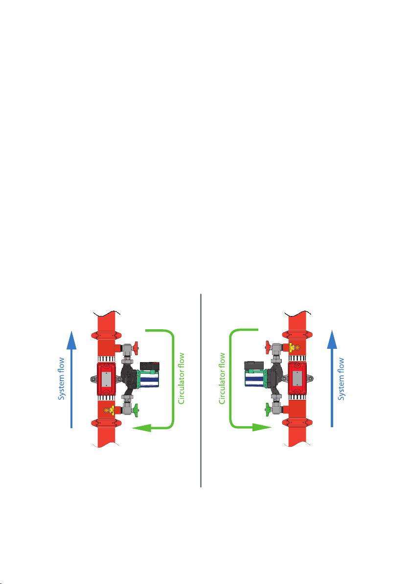
Orientation
05
Plan view
Side view
Pump not horizontalFlow-switch on underside of pipe
Remember:
• The pump direction-of-flow arrow faces the opposite direction to the system flow.
• The red & green stripes on the pump cartridge are always horizontal.
• Do not position the flow-switch on the underside of the pipe.
• For vertical flow applications, only mount flow-switch where up-flow conditions exist.
Table of contents


