ZRGP Mate LV 50 Series User manual

Power Base LV - MATE
Reference Manual
Rev 00
03/08/2021
ENGLISH

Power Base LV -MATE Series RM ZRGP Technical
Table of Contents
1. SafetyPrecautions............................................................................................................. 1
1.1. General warnings.......................................................................................................... 1
1.2. Charge and discharge warnings.................................................................................... 2
1.3. Transportation warnings............................................................................................... 3
1.4. Disposal of lithium batteries......................................................................................... 3
1.5. Before Connecting........................................................................................................ 3
1.6. In Using.........................................................................................................................4
2. Introduction...................................................................................................................... 5
2.1. Lithium iron phosphate battery.....................................................................................5
2.2. Power Base LV-MATE Features.................................................................................. 5
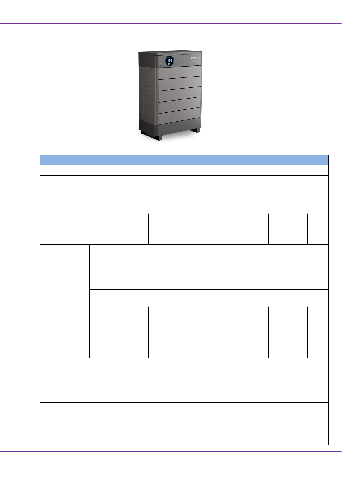
2.3. Specifications................................................................................................................6
2.4. Equipment Interface Instruction................................................................................... 7
2.5. Sleep and Wake up........................................................................................................9
2.5.1 Sleep.........................................................................................................................14
2.5.2Wake up.................................................................................................................... 14
3. How to use the ZRGP EmsTools................................................................................... 11
3.1. ZRGP EmsTools connection.......................................................................................15
4. How to match communication with inverter..................................................................18
4.1. Supported brands........................................................................................................ 19
4.2. Inverter matching list.................................................................................................. 22
4.3. Connection with inverter.............................................................................................22
5. Safe handling of lithium batteries Guide........................................................................24
5.1. Schematic Diagram of Solution.................................................................................. 24
5.2. Familiar with batteries................................................................................................ 24
5.3. Precautions before installation....................................................................................25
5.4. Tools........................................................................................................................... 25
5.5. Safety Gear..................................................................................................................25
6. Installation...................................................................................................................... 26
6.1. Package Items............................................................................................................. 27
6.2. Installation Location................................................................................................... 28
6.3. Parallel Installation..................................................................................................... 29
7. Trouble Shooting Steps.................................................................................................. 30
7.1. Problem determination based on.................................................................................30
7.2. Preliminary determination steps................................................................................. 30
7.3. The battery cannot be charged or discharged............................................................. 30
8. Storage,Transportationand Emergency Situations......................................................... 31
8.1. Storage........................................................................................................................ 31
8.2. Transportation............................................................................................................. 31
8.3. Emergency Situations................................................................................................. 31

Power Base LV -MATE Series RM ZRGP Technical
Page 1Chapter 1: Safety Precautions
1. Safety Precautions
It is very important and necessary to read the user manual carefully (in the accessories) before
installing or using battery. Failure to do so or to follow any of the instructions or warnings in
this document can result in electrical shock, serious injury, or death, or can damage battery,
potentially rendering it inoperable.
1.1. General warnings
Any uncovered battery material such as electrolyte or powder on the skin or in the
eyes must be flushed with plenty of clean water immediately. Then seek medical
assistance. Spillages on clothing should be rinsed out with water.
Explosion and fire hazard. Terminals of the Li-ion Battery are always alive;
therefore, do not place items or tools on the Li-ion Battery. Avoid short circuits, too
deep discharges and too high charge currents. Use insulated tools. Do not wear any
metallic items such as watches, bracelets, etc. In case of fire; you must use a type D,
foam or CO2 fire extinguisher.
Do not open or dismantle the battery. Electrolyte is very corrosive. In normal
working conditions contact with the electrolyte is impossible. If the battery
casing is damaged do not touch the exposed electrolyte or powder because it
is corrosive.
Observe these instructions and keep them located near the Li-ion Battery for
future reference.
For more information about this product, please visit the official
website:http://www.zruipower.com
Work on a Li-ion Battery should be carried out by qualified personnel only.
While working on the Li-ion Battery wear protective eyeglasses and clothing.
Li-ion batteries are heavy. If involved in an accident they can become a
projectile! Ensure adequate and secure mounting and always use suitable
handling equipment for transportation.
Handle with care because a ion battery is sensitive to mechanical shock.
Do not expose cable outside, all the battery terminals must be disconnected
for maintenance.
Do not place at a children or pet touchable area.
Do not use cleaning solvents to clean battery.

Power Base LV -MATE Series RM ZRGP Technical
Page 2Chapter 1: Safety Precautions
1.2. Charge and discharge warnings
If the battery is stored for long time, it is required to charge them every six months,
and the SOC should be no less than 90%.
SOCshould be no lessthan90%
Use only with a ZRGP approved BMS.
If charged after the Lithium Battery was discharged below the “Discharge cut-off
voltage”, or when the Lithium Battery is damaged or overcharged, the Lithium
Battery can release a harmful mixture of gasses such as phosphate.
The temperature range over which the battery can be charged is 0°C to 45°C.
Charging the battery at temperatures outside this range may cause severe damage to
the battery or reduce battery life expectancy.
The temperature range over which the battery can be discharged is -10°C to 55°C.
Discharging the battery at temperatures outside this range may cause severe damage
to the battery or reduce battery life expectancy.
Do not drop, deform, impact, cut or spearing with a sharp object.
Do not wet the battery and avoid of direct sunlight.
Do not use a damaged battery.
Please contact the supplier within 24 hours if there is something abnormal.
Do not expose battery to flammable or harsh chemicals or vapors.
Do not paint any part of battery; include any internal or external components.
Battery needs to be recharged within 12 hours, after fully discharged.
Do not connect battery with PV solar wiring directly.
Any foreign object is prohibited to insert into any part of battery.
The warranty claims are excluded for direct or indirect damage due to items above.

Power Base LV -MATE Series RM ZRGP Technical
Page 3Chapter 1: Safety Precautions
1.3. Transportation warnings
NOTE
:
●Batteries are tested according to UN Handbook of Tests and Criteria, part III, sub section 38.3
(ST/SG/AC.10/11/Rev.5).
●For transport the batteries belong to the category UN3480, Class 9, Packaging Group II and have to be
transported according to this regulation. This means that for land and sea transport (ADR, RID & IMDG) they
have to be packed according to packaging instruction P903 and for air transport (IATA) according to packaging
instruction P965. The original packaging complies with these instructions.
1.4. Disposal of lithium batteries
1.5. Before Connecting
◆After unpacking, please check product and packing list first, if product is damaged or lack of
parts, please contact with the local retailer;
◆Before installation, be sure to cut off the grid power and make sure the battery is in the
turned-off mode;
◆Wiring must be correct, do not mistake the positive and negative cables, and ensure no short
circuit with the external device;
◆It is prohibited to connect the battery and AC power directly;
◆The embedded BMS in the battery is designed for 48V DC, please DO NOT connect battery
in series;
◆Battery system must be well grounded and the resistance must be less than 1oumu;
◆Make sure the grounding connection set correctly before operation.
The battery must be transported in its original or equivalent package and in an
upright position. If the battery is in its package, use soft slings to avoid damage.
Do not stand below a battery when it is hoisted.
Never lift the battery at the terminals or the BMS communication cables, only lift the
battery at the handles.
Batteries marked with the recycling symbol must be processed via a recognized
recycling agency. By agreement, they may be returned to the manufacturer.
Batteries must not be mixed with domestic or industrial waste.
Do not throw a battery into fire.

Power Base LV -MATE Series RM ZRGP Technical
Page 4Chapter 1: Safety Precautions
◆Please ensured the electrical parameters of battery system are compatible to related
equipment;
◆Keep the battery away from water and fire.
1.6. In Using
◆If the battery system needs to be moved or repaired, the power must be cut off and the battery
is completely shutdown;
◆It is prohibited to connect the battery with different type of battery.
◆It is prohibited to put the batteries working with faulty or incompatible inverter;
◆It is prohibited to disassemble the battery (QC tab removed or damaged);
◆In case of fire, only dry powder fire extinguisher can be used, liquid fire extinguishers are
prohibited;
◆Please do not open, repair or disassemble the battery except staffs from ZRGP or authorized
by ZRGP. We do not undertake any consequences or related responsibility which because of
violation of safety operation or violating of design, production and equipment safety standards.

Power Base LV -MATE Series RM ZRGP Technical
Page 5Chapter 2: Introduction
2. Introduction
Power Base LV -MATE series lithium iron phosphate battery is one of new energy storage
products developed and produced by ZRGP, it can be used to support reliable power for various
types of equipment and systems. Power Base LV -MATE series is especially suitable for
application scene of high power, limited installation space, and restricted load-bearing and long
cycle life.
Power Base LV_MATE series has built-in BMS battery management system, which can
manage and monitor cells information including voltage, current and temperature. What’s more,
BMS can help extending cycle life by balancing cells during charging and discharging.
Multiple batteries are allowed to be connected in parallel to expand capacity and power to meet
the requirements of longer power supporting duration and higher power consumption.
2.1. Lithium iron phosphate battery
The lithium iron phosphate battery (LiFePO4 or LFP) is the safest of the mainstream lithium
battery types. A single LFP cell has a nominal voltage of 3.2V. A 51.2V LFP battery consists
of 16 cells connected in series.
LFP is the chemistry of choice for very demanding applications. Some of its features are:
◆Rugged - It can operate in deficit mode during long periods of time.
◆High round trip efficiency.
◆High energy density - More capacity with less weight and volume.
◆High charge and discharge currents - Fast charge and discharges are possible.
◆Flexible charge voltages.
The lithium iron phosphate battery is therefore the chemistry of choice for a range of very
demanding applications.
2.2. Power Base LV -MATE Features
◆The whole module is non-toxic, pollution-free and environment-friendly;
◆Cathode material is made from LiFePO4 with safety performance and long cycle life;
◆Battery management system (BMS) has protection functions including over-discharge,
over-charge, and over-current and high/low temperature;
◆The system can automatically manage charge and discharge state and balance current and
voltage of each cell;
◆Flexible configuration, multiple battery modules can be internal for expanding voltage and
Capacity.
◆Adopted self-cooling mode rapidly reduced system entire noise;
◆The module has less self-discharge, up to 6 months without charging it on shelf, no memory
effect, excellent performance of shallow charge and discharge;
◆Working temperature range is from -10 to 55 ℃, (Charging 0~45 ℃; discharging
-10~55℃)with excellent discharge performance and cycle life;
◆Small volume, light weight, plug-in embedded design module, easy to install and maintain;

Power Base LV -MATE Series RM ZRGP Technical
Page 6Chapter 2: Introduction
2.3. Specifications
Figure 2.1.Overall system diagram
No.
Items
Parameters
1
Model
Mate LV_50 Series
Mate LV _100 Series
2
Main Control Module
ZR-MC100-200M1
ZR-MC100-200M2
3
Battery Module Type
ZR-FS4850-16OSJ1
ZR-FS48100-16OSJ1
4
Battery Module Chemistry
LiFePO4
5
Battery Module QTY
2
3
4
5
8
2
3
4
5
8
6
Nominal Capacity(Ah)
100
150
200
250
400
200
300
400
500
800
7
Nominal Energy(kWh)
5.12
7.68
10.24
12.8
20.48
10.24
15.36
20.48
25.6
40.96
8
Voltage
Nominal(V)
51.2
Recommend
Charging(V)
56.8
Max.
Charging(V)
58.4
Discharge
Cut-off(V)
46.8
9
Current
Max.
Charging(A)
50
75
100
125
125
75
100
125
125
125
Max.
Discharging(A)
85
125
175
210
210
175
210
210
210
210
Peak for 10s(A)
90
135
180
211
211
180
211
211
211
211
10
Weight (Approx.)
165kg @12.8 kWh
236kg @25.6 kWh
11
Dimensions (L*H*W))
635 x 965 x 350 mm @12.8 kWh
735*1040 *400mm @25.6 kWh
12
Communication
RS485, CAN
13
Cycle Life
4000 times@80%DOD
14
Designed Calendar Life
≥10 years
15
Safety Function
Over-charge, Over-discharge, Over-current, Low/High-temperature, Low-voltage,
Short-circuit Protections
16
Parallel Capability
Maximum 8 units (Recommended 6 units)

Power Base LV -MATE Series RM ZRGP Technical
Page 7Chapter 2: Introduction
2.4. Equipment Interface Instruction
Figure 2.2.Main control module positive
Figure 2.3.Interface definition of main control module
No.
Instructions
No.
Instructions
1
Address Dial Switch
8
Reserve
2
Inverter CAN /RS485communication port
9
Reserve
3
Reserve
10
Parallel communication port B
4
Inverter CAN communication port
11
Parallel communication port A
5
Inverter RS485communication port
12
Charge and discharge positive electrode
6
CAN upgrade communication port
13
Charge discharge negative electrode
7
RS232 communication interface
14
No.
Instructions
NO.
Instructions
1
Power switch
2
Display screen
3
Status code
8
9
10
11
4
5
6
7
2
3
1
12
13
1
2
3

Power Base LV -MATE Series RM ZRGP Technical
Page 8Chapter 2: Introduction
Display screen
Power switch
Power switch: turn on/off the input and output of the whole system.
Display screen: the interface can observe the operation status information SOC, SOH, charging
and discharging power, alarm fault indication, charging and discharging status display and
system status indication of the whole system.
Status code
Status code:When the system status code is displayed as protection information, only the value
will be displayed. When the system status code is displayed as fault information, err and fault
value will be displayed The definition of alarm is shown in the table below:
numerical value
Alarm indication
numerical value
Alarm indication
000
No breakdown
009
Low discharge
temperature
001
Over voltage
protection
011
High ambient temperature
002
Low voltage protection
012
Excessive differential
pressure
003
Charging over current
protection
013
Discharge circuit failure
004
Discharge over current
protection
014
Charging circuit fault
005
Short circuit protection
015
Cell failure
006
Charging high
temperature
016
NTC failure
007
High discharge
temperature
017
Voltage acquisition fault
008
Low charging
temperature
NOTE:
●When the system is charged, the display streamline gathers in the middle, and when it is discharged, the display
streamline disperses to both sides
Master address dial switch
Dial switch: 4-digit dial switch, address "0" and "1", as shown in the figure.
After setting, you need to restart the system and activate it.
When the system groups are in parallel, the communication between two levels is needed. Both
master and slave packets need hardware address configuration, and the hardware address can be
set through the dial switch on the board. The definition of switch is shown in the table below.

Power Base LV -MATE Series RM ZRGP Technical
Page 9Chapter 2: Introduction
Address
Coding
Dial Code Switch
Position
Definition
#1
#2
#3
#4
1
ON
OFF
OFF
OFF
The host computer can monitor the operation of other systems by
setting the main package
2
OFF
ON
OFF
OFF
Set to the slave Pack 2
3
ON
ON
OFF
OFF
Set to the slave Pack 3
4
OFF
OFF
ON
OFF
Set to the slave Pack 4
5
OFF
ON
ON
OFF
Set to the slave Pack 5
6
ON
OFF
ON
OFF
Set to the slave Pack 6
7
ON
ON
ON
OFF
Set to the slave Pack 7
8
OFF
OFF
OFF
ON
Set to the slave Pack 8
9
ON
OFF
OFF
ON
Set to the slave Pack 9
10
OFF
ON
OFF
ON
Set to the slave Pack10
11
ON
ON
OFF
ON
Set to the slave Pack 11
12
OFF
OFF
ON
ON
Set to the slave Pack 12
13
ON
OFF
ON
ON
Set to the slave Pack13
14
OFF
ON
ON
ON
Set to the slave Pack 14
15
ON
ON
ON
ON
Set to the slave Pack 15
Inverter CAN/RS485 communication port
Inverter CAN/RS485 communication port: (RJ45 port) follows can protocol and RS485
protocol. For the output system information, the system master uses this interface to
communicate with External inverter PC and other equipment.
Port definitions
RJ45 Pin
Function
1
RS485-B
2
RS485-A
3
RS485 -GND
4
CAN-L
5
CAN-H
6
CAN -GND
1
2
3
4
5
6

Power Base LV -MATE Series RM ZRGP Technical
Page 10 Chapter 2: Introduction
RS232 communication port
RS232 communication port: (RJ11 port) comply with RS232 protocol (baud rate: 9600), for
manufacturers or professional engineers debugging or service.
Port definitions
RJ11 Pin
Function
1
NC(NO connect)
2
NC(NO connect)
3
RS232-GND
4
RS232-TX
5
RS232-RX
6
RS232-GND
7
NC(NO connect)
8
NC(NO connect)
COM communication port
COM communication port:Connect the monitoring host computer to query the data and monitor
the running status of the system
Port definitions
RJ45 Pin
Function
1
RS485-B
2
RS485-A
3
CAN -GND
4
RS485-GND
5
RS485-GND
6
CAN -GND
7
CAN-L
8
CAN-H
Inverter RS485 communication port
Rear panel RS485 communication port: (RJ45 port) follows can protocol and RS485 protocol.
For the output system information, the system master uses this interface to communicate with
External inverter PC and other equipment.

Power Base LV -MATE Series RM ZRGP Technical
Page 11 Chapter 2: Introduction
Port definitions
RJ45 Pin
Function
1
RS485-B
2
RS485-A
3
RS485-GND
4
NC(NO connect)
5
NC(NO connect)
6
RS485-GND
7
RS485-A
8
RS485-B
Inverter CAN communication port
Rear panel CAN communication port: (RJ45 port) follows can protocol and RS485 protocol.
For the output system information, the system master uses this interface to communicate with
External inverter PC and other equipment.
Port definitions
RJ45 Pin
Function
1
CAN-H
2
CAN-L
3
CAN -GND
4
CAN-H
5
CAN-L
6
CAN -GND
7
CAN-H
8
CAN-L
Rear panel Link A / Link B communication port
Link A / B communication port: the definition of link a and B on the rear panel of the interface
main control module is the same. RS485 interface is used for parallel communication between
the main control modules, and up to 15 devices can be connected in parallel.
Port definitions
RJ45 Pin
Function
1
RS485-B
2
RS485-A
3
RS485-GND
4
NC(NO connect)
5
NC(NO connect)
6
RS485-GND
7
RS485-A
8
RS485-B

Power Base LV -MATE Series RM ZRGP Technical
Page 12 Chapter 2: Introduction
Figure 2.4. Battery module interface definition
Power switch
Power switch: turn on / off the input and output of the whole battery module.
RS232 communication port
RS232 communication port: (RJ11 port) comply with RS232 protocol (baud rate: 9600), for
manufacturers or professional engineers debugging or service.
Port definitions
RJ11 Pin
Function
1
NC
2
RS232-GND
3
RS232-TX
4
RS232-RX
5
RS232-GND
6
NC
Address dial switch
ADD Switch: 6 ADD switches, “0”and “1”, refer to picture right.The
settings will be active only after restart the battery.
When the battery communicates with the inverter, the address of the battery pack must be set to
1, and the address of the parallel slave should be greater than 1.
When the battery Pack is connected in parallel, cascading communication is required.
Hardware address configuration is required for both the master PACK and the slave PACK, and
No.
Instructions
NO.
Instructions
1
Address Dial Switch
2
RS232 communication interface
3
Power switch
1
2
3

Power Base LV -MATE Series RM ZRGP Technical
Page 13 Chapter 2: Introduction
the hardware address can be set by the dial switch on the board. The definition of the switch
refers to the table below.
Address
Coding
Dial Code Switch Position
Definition
#1
#2
#3
#4
#5
#6
1
ON
OFF
OFF
OFF
OFF
OFF
Set the master Pack, and the inverter communicates
with the battery at that address
2
OFF
ON
OFF
OFF
OFF
OFF
Set to the slave Pack1
3
ON
ON
OFF
OFF
OFF
OFF
Set to the slave Pack 2
4
OFF
OFF
ON
OFF
OFF
OFF
Set to the slave Pack 3
5
ON
OFF
ON
OFF
OFF
OFF
Set to the slave Pack 4
6
OFF
ON
ON
OFF
OFF
OFF
Set to the slave Pack 5
7
ON
ON
ON
OFF
OFF
OFF
Set to the slave Pack 6
8
OFF
OFF
OFF
ON
OFF
OFF
Set to the slave Pack 7
9
ON
OFF
OFF
ON
OFF
OFF
Set to the slave Pack 8
10
OFF
ON
OFF
ON
OFF
OFF
Set to the slave Pack 9
11
ON
ON
OFF
ON
OFF
OFF
Set to the slave Pack10
12
OFF
OFF
ON
ON
OFF
OFF
Set to the slave Pack 11
13
ON
OFF
ON
ON
OFF
OFF
Set to the slave Pack 12
14
OFF
ON
ON
ON
OFF
OFF
Set to the slave Pack13
15
ON
ON
ON
ON
OFF
OFF
Set to the slave Pack 14
16
OFF
OFF
OFF
OFF
ON
OFF
Set to the slave Pack 15
62
OFF
ON
ON
ON
ON
ON
Set to the slave Pack 61
63
ON
ON
ON
ON
ON
ON
Set to the slave Pack 62
Battery anode and Battery cathode
Positive and negative connection: the battery modules are connected in
parallel through the connecting terminals, and finally the main control
module is connected in parallel. The power cable adopts waterproof
connector. When connecting the power plug, its corresponding interface
must be aligned.

Power Base LV -MATE Series RM ZRGP Technical
Page 14 Chapter 2: Introduction
2.5. Sleep and Wake up
2.5.1 Sleep
2.5. Wake up
2.5.1 sleep
1) The main control module will turn off the main relay when the battery module has a charging
and discharging MOS fault.
2) When the battery module has the output of under voltage protection battery shutdown, the
main control closes the main relay.
2.5.2Wake up
When the system is in sleep mode, after completing the operation, the system will exit the low
power mode and enter the normal operation mode:
1) Connect the charger, and the output voltage of the charger must be greater than 48V.
2) Connect the upper computer to observe whether the communication between the main
control and the battery is normal
3) Observe whether the upper computer has charging current.
4) After successful charging, the system will enter normal mode.
Note:
●when the DC bus has a voltage greater than 48V DC, the system main control module is
powered and the main relay is closed to charge the battery module and establish communication.
If the battery module cannot charge and establish communication, the main control module will
delay about 10s to disconnect the main relay
2.6.Forced discharge mode
When the battery is in the sleep mode of under voltage protection and the minimum battery
voltage is greater than 2.0V, turn off the power switch first, wait for 2S, and then turn on the
power switch. The battery enters the forced discharge mode for 5 minutes. In the forced
discharge mode, the battery powered main control inverter works. If the inverter is connected to
the commercial power to charge the system, the battery will exit the forced discharge mode and
switch to the normal mode. If the on load discharge current of the inverter exceeds 20A or there
is no charging current within 5 minutes, the battery will enter the sleep mode again.
2.7.Automatic parallel
With automatic parallel function; when the slave battery (address > 1) is powered on, the charge
and discharge switch is in disconnect state. When the voltage difference between the slave
battery and master battery is less than the condition of "the minimum voltage difference
between the slave and the master", the master sends the command to the slave. After the slave
receives the command from the master, the charge and discharge switch will be connected and
the slave is integrated into the master system to complete the parallel operation.

Power Base LV -MATE Series RM ZRGP Technical
Page 15 Chapter 3: How to use the ZRGP Ems Tools
3. How to use the ZRGP Ems Tools
3.1. ZRGP Ems Tools connection
1) Connect the RS485 interface of the battery to the computer using the RS485
communication line (this accessory is an optional accessory, need to be purchased separately
from the manufacturer).
2) Unzip the package file of the ZRGP Ems Tools in the same file directory, pay attention to
the directory do not store other files.
Figure 3.1. Unzip of ZRGP Ems Tools
3) Open the ZRGP Ems tools icon, enter the Protocol selection interface, select the EMS Low
Voltage Protocol version and enter the password (please contact the manufacturer for the
password) to log in the software.
Figure 3.2. Protocol selection interface Figure 3.3. Enter the password
4) Users can set different languages according to their own needs. We support four languages,
which are Simplified Chinese, English, Japanese and Spanish.
Figure 3.4. ZRGP Ems tools language selection
5) Select the serial port number in the EMS low-voltage version of the ZRGP Ems tools, and

Power Base LV -MATE Series RM ZRGP Technical
Page 16 Chapter 3: How to use the ZRGP Ems Tools
the baud rate is 9600 by default. Click "Open COM" and "Monitor ON" button.
Figure 3.5. ZRGP Ems tools serial port settings
6)The corresponding functions can be selected through the navigation bar of the ZRGP EMS .
Figure 3.6. ZRGP Ems data acquisition
7)Cluster information operation information, you can select the corresponding operation
information through the navigation bar. A total of 15 clusters can be
monitored.
Series Port
Navigation bar

Power Base LV -MATE Series RM ZRGP Technical
Page 17 Chapter 3: How to use the ZRGP Ems Tools
Figure 3.7. ZRGP Cluster data acquisition
8)The configuration parameter interface displays the manufacturer identification, software
version, hardware version, production serial number, temperature quantity and module battery
quantity of a cluster in real time.
Figure 3.8. ZRGP Cluster Matching parameters
9)The interface displays the running information of the battery module in real time. The
module running parameter interface can monitor up to 15 battery modules, and select the
module through the pack button on the interface your address.
Password for Parameter Setting
Navigation bar

Power Base LV -MATE Series RM ZRGP Technical
Page 18 Chapter 3: How to use the ZRGP Ems Tools
Figure 3.8. Module operation parameters
10) The system setting interface can read and write the number of clusters, the number of
cluster modules,the Precharge time, the main control address and the inverter protocol of the
system. When writing the parameters, the system setting password is required.
Figure 3.9. System setting interface
11)The interface can read and set the working parameters of the system, battery protocol, baud
rate of can module, baud rate of RS-485 module, charging and discharging control and system
time. It also has the functions of eliminating alarm sound, restoring factory setting, saving
parameters and importing parameters.
Module
location
System setup password
This manual suits for next models
1
Table of contents
Other ZRGP Storage manuals
Popular Storage manuals by other brands

Serial Cables
Serial Cables PCIe Gen4 U2 8Bay Active JBOF user manual

Qsan
Qsan AegisSAN Q500 Series user manual

NetApp
NetApp H600S Series Installation and setup instructions

Fujitsu
Fujitsu MAG3182FC SERIES product manual

Raidon
Raidon iR2777-S3 Quick installation guide

Panasonic
Panasonic RP-SDRC08GSK operating instructions

SMART Embedded Computing
SMART Embedded Computing NVME-M.2-1TB quick start guide

Ezquest
Ezquest B40160 supplementary guide

Infrant Technologies
Infrant Technologies ReadyNAS 600B installation guide

DataStor
DataStor Compaq Proliant Ultra2 SCA installation guide

Manhattan
Manhattan 709019 user manual

Buffalo
Buffalo LinkStation LS-LGL user manual