ZyCast digi-MOD HD-2002DM Manual

HD-2002DM Dual Input DVB-T HD
Encoder / Modulator
User Guide and Install Manual
Table of Contents
Radio Frequency Range
digi-MOD HD-2002DM
Safety Precautions .................................................................................................................................................................... 2
Package Contents ..................................................................................................................................................................... 2
Product Description ................................................................................................................................................................... 2
.............................................................................................................................................................................. 3
Installation ................................................................................................................................................................................. 4
Hardware Installations and Connections................................................................................................................................... 4
Connecting to the GUI Interface................................................................................................................................................ 4
Encoder Programming and Setup via GUI Interface ................................................................................................................. 5
Overview Page of digi-MOD HD Encoder ................................................................................................................................. 5
Common Setup .................................................................................................................................................... 6
RF Setup.............................................................................................................................................................. 7
Encoder Setup ..................................................................................................................................................... 7
......................................................................................................................................... 8
Administration ...................................................................................................................................................... 9
................................................................................................................................................... 9
Installing Multiple Encoders in the Same Installation (Stacking) ............................................................................................. 10
Front Panel LCD Encoder Menu Map ......................................................................................................................................11
......................................................................................................................... 12
Network Setup ................................................................................................................................................... 14
www.digi-modbyzycast.com
ZyCastR

HD-2002DM User Guide and Install Manual Page 2
Safety Precautions
Package Contents
Product Description
The presence of this symbol is to alert the installer and user to the presence of uninsulated dangerous voltages within the product’s
enclosure that may be of sufcient magnitude to produce a risk of electric shock.
TO REDUCE THE RISK OF FIRE OR ELECTRIC SHOCK, DO NOT EXPOSE THIS DEVICE TO RAIN OR MOISTURE.
DO NOT OPEN THE UNIT. REFER SERVICING TO QUALIFIED PERSONNEL ONLY.
• Do not apply power to the unit until all connections have been made, all components have been installed and all wiring has
been properly terminated.
• Do not terminate, change or uninstall any wiring without rst disconnecting the unit’s power adapter from the device.
• This device is supplied with the appropriately rated power supply. The use of any other power supply could cause damage and
invalidate the manufacturer’s warranty.
• Do not connect the power cord to the device if the power cord is damaged.
• Do not cut the power cord.
• Do not plug the power cord into an AC outlet until all cables and connections to the device have been properly connected.
• The device should be installed in an environment consistent with its operating temperature specications. Placement next to
heating devices and ducts is to be avoided as doing so may cause damage. The device should not be placed in areas of high
humidity.
• Do not cover any of the device’s ventilation openings.
• Do not cover or obstruct the device’s fan or fan openings.
• If the device has been in a cold environment allow it to warm to room temperature for at least 2 hours before connecting to an
AC outlet.
This package contains:
• One HD-2002DM Encoder / Modulator
• One power cable
• One installation / conguration manual
Inspect the package before starting installation to ensure there is no damage and all supplied contents are present. Contact your
distributor or dealer should the device be damaged or package contents are incomplete.
Resi-linx digi-MOD HD Series Encoder/ Modulators provides a DVB-T - making it ideal for any Commercial RF Network. The high
quality HD design allows for watching action packed movies and sports channels on any HDTV. The optional AC-3 Dolby Audio and
AES-128 Encryption capabilities rounds out the feature rich product series. The space saving design delivers up to 4 High Quality
HD DVB-T channels in a single 1RU space.
• Front panel LCD Display for easy installation
• High Resolution up to 1080i/1080p
• LCN MODE
• Composite, Component, and HDMI (unencrypted) inputs
• MPEG2 or MPEG4 (H.264) Video Output
• Selectable Constellation
• Closed Captioning Support
• 100dB Output
• Rack mountable 1RU height
Front Panel
Rear Panel

HD-2002DM User Guide and Install Manual Page 3
Specication
VIDEO INPUTS (VIDEO BY PRIORITY)
HDMI 1.4v
Component YPrPb (RCA)
Composite CVBS (RCA)
AUDIO INPUTS
Audio Inputs L/R (RCA)
VIDEO ENCODER
Mode MPEG-2, MPEG-4 (H.264)
Video Resolutions 1080p (MPEG-4 Only), 1080i, 720p, 576p, 576i, 480p, 480i
AUDIO ENCODER
Audio Compression MPEG-1 Layer II, AAC, AC-3 Pass Through
RF DVB-T SUPPORT
Frequency Channel Plan - Varies by Country
RF Channel Output 2 multiplexed on to 1 RF Output
Constellation 64QAM (16QAM)
Bandwidth 7 MHz
RF Level Output 100dB
MER >40dB Typical
FEC 1/2, 2/3, 3/4, 5/6, 7/8
Guard Interval 1/4, 1/8, 1/16, 1/32
OFDM 8K (2K)
Attenuation 1-20dB (1dB steps)
RF Output "F" - Female 75 ohm
Closed Captioning Control By Selection (use of CVBS Input)
MANAGEMENT / CONTROL
Front Panel LCD Control Full Support (Up/Down/OK Buttons)
GUI IE9, Firefox, Chrome, Safari
Password Protected Front Panel, GUI
GENERAL
Rack Mountable (1RU) 482.7mm x 240mm x 44.4mm - 19" EIA Standard
Internal Fan Cooled Dual Internal
LCD Front Panel Dual Line, Scrolling Display
**Subject to change without notice

HD-2002DM User Guide and Install Manual Page 4
System Installer must adhere to Article 820-40 of the NEC that provides guidelines for proper grounding and species
that the cable ground shall be connected to the grounding system of the building, as close to the point of cable entry
as possible.
UNPACKING AND INSPECTION
Each unit is shipped factory tested. Ensure all items are removed from the container prior to discarding any packing material.
Thoroughly inspect the unit for shipping damage with particular attention to connectors and controls. If there is any sign of damage
to the unit or damaged or loose connectors contact your distributor immediately. Do not put the equipment into service if there is
any indication of defect or damage.
It is highly recommended that quality cables and connectors be used for all video and audio source connections.
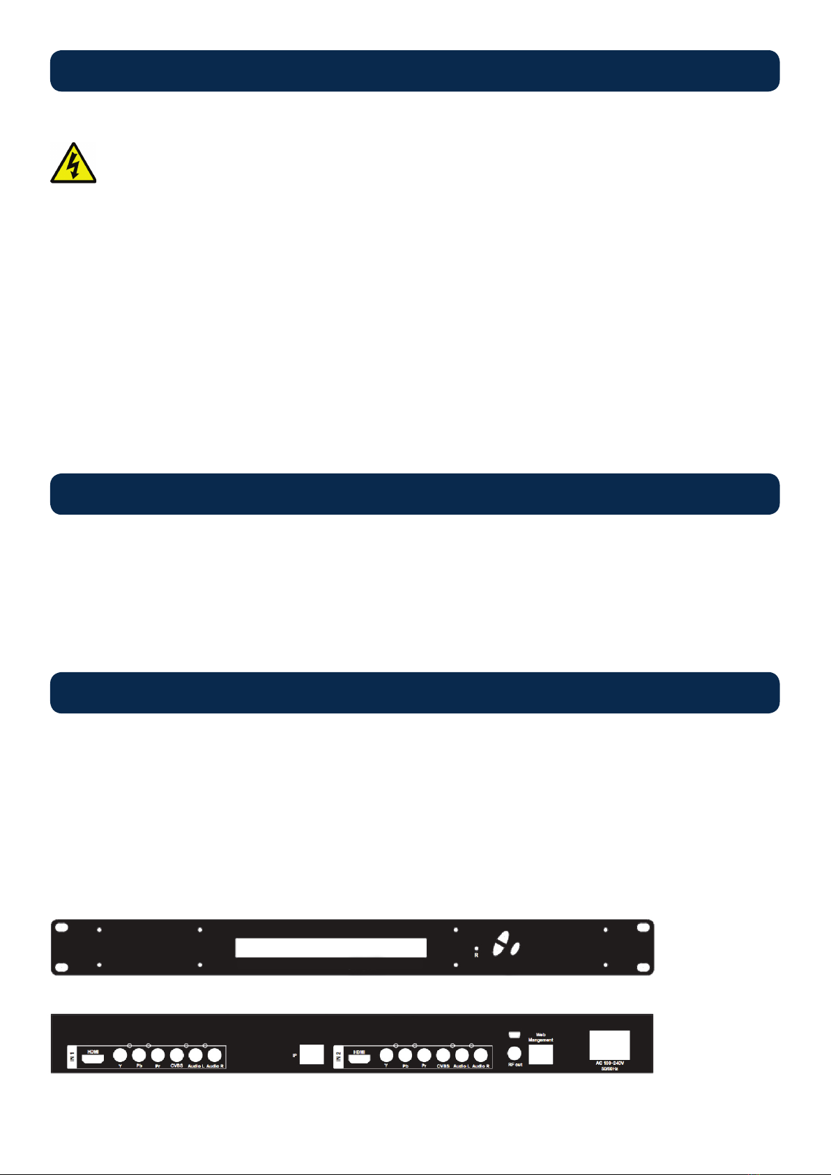
1. The unit is designed to be rack mounted in a standard EIA 19” rack.
2. The unit comes standard with HDMI, Component, and Composite video inputs. The HDT encoder / modulator are intelligently
designed to detect the video input from the video source. HDMI Connection: Connect the HDMI cable(s) from the video
source(s) into the HDMI input(s). If using a Component Video Cable, connect the Y (Green), Pb (Blue), and Pr (Red) video
source cable to the unit’s Component input ports. If using a Composite Video source, use a 75Ω coaxial cable with RCA
connectors to connect the video source (e.g., CATV, DVD, VCR, Camera) to the unit’s CVBS port (IN1…IN2, IN3, IN4
depending on your model).
3. Repeat this step for each video source connection.
4. Component / Composite Audio inputs: Connect A/V audio input (Left / Right Audio) use RCA cables to connect the audio
source to the red / white AUDIO L and AUDIO R INPUT jacks (IN1…IN2, IN3, IN4 depending on your model). Repeat this step
for each audio source connection.
5. Be sure the video and audio connections for each source are consistent with the unit’s inputs (IN1…IN2, IN3, IN4 depending on
your model).
6. Use a quality 75Ω coaxial cable with “F” connectors from the unit’s RF OUT jack to the distribution system (combiner or
reverse splitter) or directly to a television.
7. If your device is equipped with an IP output- connect the Ethernet cable to the IP output RJ45 connector.
8. Connect the included power cord to the unit’s POWER plug.
9. Connect the power cord to an appropriately rated AC power outlet.
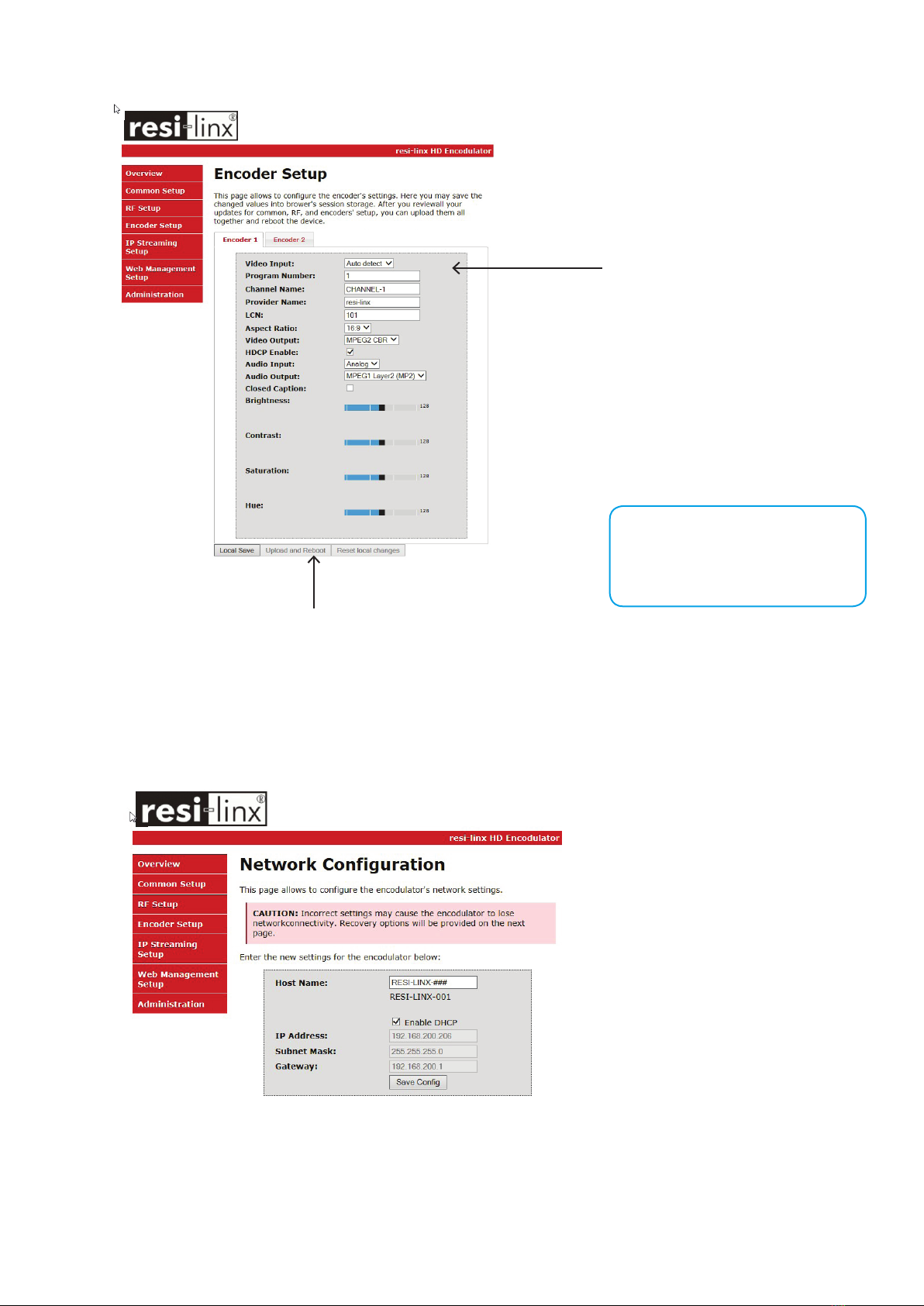
To setup and program the Encoder you can use the GUI interface or the LCD Front Panel.
1. Connect an Ethernet cable directly (no Cross Over cable required) to the Web Management Port on the rear panel of the
encoder or connect the Ethernet cable to an Ethernet switch. Connect an Ethernet Cable to your PC.
2. Using a Windows-based PC Select Windows Icon
3. Go to My Computer
4. Select Network
5. Allow UPnP to locate and list the device(s) in the right panel
6. Right Click and Select “View device Webpage”.
Installation
Hardware Installations and Connections
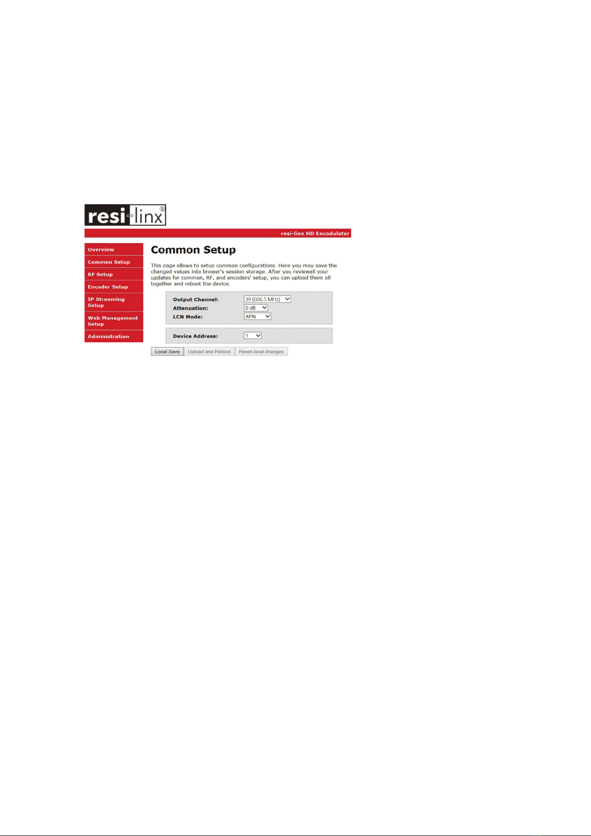
DEVICE Programming and Setup
Connecting to the GUI Interface
NOTE:
For Setup Using Front Panel LCD:
Go to page 11 in this manual.

HD-2002DM User Guide and Install Manual Page 5
After connecting the device to the “Web Management” port located on the rear of the device and locating the device via the
‘Network’ tool in ‘My Computer’
STEP 1: Right Click and Select “View device Webpage”.
Overview status of the Encoder when fully functioning. Alternate between viewing status of RF Output 1 and RF Output 2 by
selecting the RF Output section of the device you want to monitor.
STEP 2: Login Select Common Setup
Once the Common Setup Tab is selected you will be prompted to enter the user name and password for device:
STEP 3: Common Setup Tab
Common Setup: Use the Common Setup Page to set the Output channel, Attenuation, LCN Mode, and Device Address.
Encoder Programming and Setup via GUI Interface
Overview page of resi-linx digi-MOD HD
NOTE:
Image displays the Quad version
of the HDT Encoder.
Default User Name: admin
Default Password: Admin123

HD-2002DM User Guide and Install Manual Page 6
STEP 4: Local Save
Once all parameters are set you are required to do a Local Save.
Notes on Changes: Changes made to an individual setup tab may require the installer to perform a Local Save AND Upload and
Reboot to the device if you are only making changes to one parameter to the encoder.
Example: Installer is required to change only the output channel for the device (No other changes to the device are not required).
Once the channel has been changed, the installer is required to perform
1. Local Save and
2. Upload and Reboot.

HD-2002DM User Guide and Install Manual Page 7
STEP 5: RF Setup
Use the RF Setup Page to setup each RF Output.
STEP 6: Local Save
Once all parameters are set you are required to do a Local Save.
NOTE:
The device shown is a QUAD input device. Your device will
not show RF Output 2 if you are setting up a Single or Dual
input encoder.
STEP 7: Encoder Setup
Select the Encoder 1, 2 tab to program an individual encoder. Select and change all desired parameters.
NOTE:
There is an Encoder tab present
for each input on the device.

HD-2002DM User Guide and Install Manual Page 8
STEP 8: Local Save for each Encoder tab
Once all parameters are set you are required to do a Local Save on EACH Encoder Tab where changes were performed
IMPORTANT NOTE:
Ensure all Encoder changes
have been locally saved before
performing Step 9.
Note: Local
Save function will
indicate the local
change made
Upload and Reboot after all changes have
been made and a Local Save performed
STEP 9: Upload and Reboot
Once you have set all the encoder settings and performed a Local Save for each encoder
Select “Upload and Reboot” after you have saved all your Local changes on each Tab. This function will upload and save all
parameters set in the Common, RF, and Encoder sections of the device.
We highly recommend you save your encoder conguration les. See Administration tab for how to back you device settings.
STEP 10: Network Conguration Tab
Use the Network Setup Tab to congure the device’s IP address, Subnet Mask, Gateway, Enable/Disable DHCP, and set Host Name.

HD-2002DM User Guide and Install Manual Page 9
STEP 11: Save Network Conguration
Save Cong: Once all parameters are set you are required to select Save Cong.
This function will reboot and save the changes setting for the Network Conguration.
STEP 12: Administration
NOTE:
Only the Network Conguration
changes will be saved.
ADMINISTRATION PAGE FUNCTIONS ACTIONS
Reboot Reboot device. All unsaved settings will be lost.
Reset to Default Reset all settings back to original factory settings
Backup Download all settings of device
Upload Upload a saved cong le
New Password Create and save new password for GUI
STEP 13: If required, change GUI Password and Submit.
This password is for access to the GUI only. The LCD front Panel Password will
not be changed and is set to prevent unauthorized users access to your device.
IMPORTANT NOTE:
We highly recommend you save your encoder
conguration les. Simply Click the “Backup” button
and the cong les will be saved to your computer.
NOTE:
When setting a new password
you must use the ‘Submit’ button.
To upload a conguration le- simply click “Choose File” then
locate the le you want to upload. Click “Upload” to install the
conguration les. This function is helpful to the installer when
installing a large number of encoders in a single system.
Saving your conguration les

HD-2002DM User Guide and Install Manual Page 10
The following changes are required when using multiple modulators in the same installation (stacking) -
• Output channel - Default is 39 UHF (606.5 MHz). If the modulators are on the same output channel as another
modulator or FTA channel the TV will not scan the channel in. Place all modulators on available channels between 6
to 12 VHF and 28 to 51 UHF (including adjacent channels - 38, 39, 40, etc.)
Note - if you plan on using channel 52 to 69 be aware of LTE transmissions as they may interfere with each other. We
recommend installing a lter.
• LCN (Logic Channel Number) - default 101. If TV tuner receives two or more LCN’s on the same number, including
FTA channels - the TV will automatically place the LCN on a free range. In Australia this is 350 and up. Suggest to go
101, 102, 103, etc.
•Channel Name - default “CHANNEL-1” this is necessary but recommended for clients to be able to identify
channels. For example “APPLE-TV”, “FOXTEL”, “DVD”, etc.
• TS ID (Transport Stream) - Default can vary per product. You will need to adjust the TS ID # on each additional
modulator up one number per modulator. For example if default is “TS ID #1” - leave on “TS ID #1”, place 2nd
modulator on “TS ID #2”, 3rd on “TS ID #3”, etc. If the TS ID is the same number the TV tuner will not scan both
channels in.
• Program Number - Default can vary per product. You may need to adjust each additional modulator Program
Number up one number per modulator. For example, if default is “Program Number - 1” - leave on “Program Number
- #1”, place 2nd modulator on “Program Number - #2”, 3rd on “Program Number - #3”, etc. If the Program Number is
the same number the TV tuner will not scan both channels in.
Note - most TVs do not have an issue with this setting but we recommend changing it just in case.
Installing Multiple Encoders in the Same Installation (Stacking)

HD-2002DM User Guide and Install Manual Page 11
Front Panel LCD Encoder Menu Map
COMMON SETUP
Output Channel
Attenuation
LCN Mode
Device Address
Default Conguration
Back to Main
RF SETUP
Select RF
Enable RF
Constellation
FEC
Guard Interval
OFDM
RF Output
Cell ID
RF TS ID
Network ID
Org Network ID
Network Name
Back to Main
ENCODER SETUP
Select Encoder
Video Input
Program Num
Channel Name
Provider Name
LCN
Aspect Ratio
Video Output
HDCP
Audio Input
Audio Output
Closed Caption
Brightness
Contrast
Saturation
Hue
Back to Main
IP STREAMING
Network Setup
Streaming Setup
Back to Main
WEB MANAGEMENT
DHCP
IP Address
Subnet Mask
Gateway
Back to Main
EXIT

HD-2002DM User Guide and Install Manual Page 12
Once the encoder is powered up it will go through its initial booting process. Once the unit has completed its initial “Booting” up
process the LCD will display IN-1..., Bit Rate information, Channel-1...., and other information in the LCD Display Window. When
visible the unit is ready for programming or operation.
The LCD will display data as it cycles through the available information.
SCREEN VIEWS
1. Inputs, Mbps, Channel Names, Video Output Type, Audio Output type
2. Use the Scroll Up/Down button to display RF-1 / RF-2 data, Physical Output Channel, Constellation, FEC setting,
OFDM Mode Selection.
3. Use the Scroll Up/Down button to display IP address
COMMON SETUP MENU
• Output Channel – Use the Scroll Up/Down button to change the output channel.
Use the Scroll Up/Down buttons to select the desired output channel. Once the
desired output channel is selected press the OK button to set the channel. The
LCD Display will show both the channel number and the frequency number of the
output channel (example: 21 480.5000MHz).
• Attenuation – Use the Scroll Up/Down button to select Attenuation. Press the OK
button to enter the Attenuation menu. Use the Scroll/Up down button to select the
desired attenuation in 1dB increments from 0 to minus 20 dB. Once the desired
attenuation level is found press the OK button to set.
• LCN – Use the Scroll Up/Down button to select LCN MODE. Press the OK button
to enter the LCN menu. Menu options are APN, NORDIG, ITC, and EACEM. Factory
default: APN. Use the Scroll Up/Down button to select the desired LCN and press he OK button to set.
• Device Address – Use the Scroll Up/Down button to select Device Address. Press the OK button to enter the Device Address
menu. Use the Scroll Up/Down to select the Desired Address ranging from 1 to 255 then press OK to set. A unique device
address is required if setting up more than 1 encoder per site. This allows the user to distinguish each device.
• Default Conguration –To reset the Encoder/Modulator back to the factory default select the Default Conguration Menu.
Press OK to enter the Default Conguration Menu. Using the Up/Down button select YES to reset all programmed settings back
to the factory default setting. Factory Default: NO.
Caution: Once the “YES” button is pressed the unit will automatically reset to the factory default settings. All settings or
changes to the encoder/modulator will be lost.
• Back to Main – Select Back to Main to escape the Common Setup Menu.
• Main Menu – To access the Main Menu rst enter the password by pressing the OK button. Use the Scroll Up/Down buttons
to enter the password. Once the password is entered press the OK button again and the LCD Screen will display “Main Menu
Common Setup”.
• Password – Use the Scroll Up/Down buttons to enter the password. Password is 0000. Press the OK button for each number
to enter the password. Press OK again after the display shows …... HD Series.
Modulator Conguration via Front Panel LCD
NOTE:
If your device is a QUAD version
the below screen will display all
input data as is cycles through
the data available.
NOTE:
The RF2 Channel Physical output
is determined by the selection
of output channel of RF1. The
Quad Encoder prevents you from
selecting the last channel in
the device. **See page 9 of this
manual for more information on
this topic.

HD-2002DM User Guide and Install Manual Page 13
RF SETUP MENU
• Select RF – Press the OK button to enter the Select RF menu. Use the Scroll Up/Down button to Select the RF section of the
Encoder. Select 1 or Select 2. The single and Dual versions of this product will have Select 1 only
• Constellation – Use the Scroll Up/Down button to select Constellation. Press the OK button to enter the Constellation menu.
Select the desired Constellation / QAM setting then press the OK button to set.
• FEC – Use the Scroll Up/Down button to select the FEC menu. Press the OK button to enter the FEC menu. Use the Scroll Up/
Down button to select the desired FEC setting and press the OK button to set.
• Guard Interval – Use the Scroll Up/Down button to select Guard Interval. Press the OK button to enter the Guard Interval
menu. Use the Scroll Up/Down button to select the desired Guard Interval and press the OK button to set.
• OFDM – Use the Scroll Up/Down button to select the OFDM menu. Press the OK button to enter the OFDM menu. Use the
Scroll Up/Down to select the OFDM 2K or 8K. Press OK to set.
• RF Output – Use the Scroll Up/Down button to select RF Output. Press the OK button to enter the RF Output menu. Menu
options are Normal, Inverted and C.W. The factory default is Normal. Use the Scroll Up/Down button to select the desired RF
Output and press the OK button to set.
• CELL ID – Use the Scroll Up/Down button to select CELL ID. Press the OK button to enter the CELL ID menu. Use the Scroll
Up/Down button to select the desired CELL ID ranging from 0 to 65535 then press the OK button to set. Factory default is 0.
• TS ID – Use the Scroll Up/Down button to select TS ID. Press the OK button to enter the TS ID menu. Use the Scroll Up/Down
button to select the desired Stream ID ranging from 0 to 65535 then press the OK button to set.
• Network ID – Use the Scroll Up/Down button to select Network ID. Press the OK button to enter the Network ID menu. Use the
Scroll Up/Down button to select the desired Network ID ranging from 0 to 65535 then press the OK button to set.
• ORG Network ID – Use the Scroll Up/Down button to select ORG Network ID. Press the OK button to enter the ORG Network
ID menu. Use the Scroll Up/Down button to select the desired ID ranging from 0 to 65535 then press the OK button to set.
• Network Name – Use the Scroll Up/Down button to select Network Name. Press the OK button to enter the Network Name
menu. Use the Scroll Up/Down buttonto select the rst character for the desired Network Name then press the OK button to set.
Repeat the process for each character in the desired Network Name. A Network Name can consist up to 16 characters.
• Back to Main – Select Back to Main to escape the RF Setup Menu.
ENCODER SETUP MENU
• Select Encoder – Use the OK button to enter the Select Encoder Menu. Using the Scroll Up/Down buttons select the encoder
you wish to program. Use the OK button to set the Encoder. Select Encoder 1, 2, 3, or 4 based on your model number. Once
Selected the Display will indicate which Encoder you are programming while in the setup function
• Video Input – Use the Scroll Up/Down button to select Video Input. Press the OK button to enter the Video Input menu. Use
the Scroll Up/Down button to select the Video Input option: Auto, Composite, Component, or HDMI. Factory default: Auto. Press
the OK button to set. The HDT series of Encoder/Modulators is designed with Intelligent Input Detection (IID) technology. If you
select Auto, the unit will detect the video input.
• Program Num – Use the Scroll Up/Down button to set 1 Program Num(Number). Press the OK button to enter the Program
Num menu. Use the Scroll Up/Down to select the Program Num ranging from 1 to 65535 then press OK to set.
• Channel Name – Use the Scroll Up/Down button to select Channel Name. Press the OK button to enter the Channel Name
menu. Use the Scroll Up/Down menu to select the rst character of the desired Channel Name then press the OK button to
set. Repeat the process until the Channel Name is completed. The Channel Name can be 7 characters long. Factory Default:
CHANNEL-1, CHANNEL-2, CHANNEL-3, CHANNEL-4.
• Provider Name – Use the Scroll Up/Down button to select Provider Name. Press the OK button to enter the Provider Name
menu. Use the Scroll Up/Down menu to select the rst character of the desired Provider Name then press the OK button to set.
Repeat the process until the Provider Name is completed.. The Provider Name can be 16 characters long.
• LCN – Use the Scroll Up/Down button to set LCN. Press the OK button to enter The Source ID menu. Use the Scroll Up/Down
to set the Source ID. Range: 1 to 999. Press OK to set.
• Aspect Ratio – Use the Scroll Up/Down button to select Aspect Ratio. Press the OK button to enter the Aspect Ratio menu.
Use the Scroll Up/Down button to select the desired Aspect Ratio option of 4:3 or 16:9 then press the OK button to set. Factory
default: 16:9.

HD-2002DM User Guide and Install Manual Page 14
• Video Output – This Encoder / Modulators may be Dual MODE Capable. The user may select to output video in either MPEG2
or MPEG-4 (4.264). Use the Scroll Up/Down button to select 1 Video Output. Press the OK button to enter the Video Output
menu. Use the Scroll Up/Down button to select the Video Output option: MPEG2 or MPEG-4. Factory default: MPEG2. Press
the OK button to set.
NOTE:
The Dual and Quad Input allows the installer to select a combination of
Video Output formats. Some versions of this device will allow the user to
have both outputs broadcasting in either MPEG2 or MPEG4 (H.264) or a
combination of both MPEG2 and MPEG4 (H.264).
NOTE:
When using closed captioning- user must connect from the content source the composite output or cc output source
to the encoder’s cvbs input connector.
NOTE:
It is the installers / property owner / integrator’s responsibity to contract with the service provider regrding content
authoization and the use of HDCP.
• HDCP – Use the Scroll Up/Down button to select the HDCP menu- Use the Scroll Up/Down button to select the HDCP menu.
Press the OK button to enter the HDCP menu. Select Enable / Disable. Each Encoder will require you to Enable the HDCP
option.
• Audio Input – Use the Scroll Up/Down button to select. Press the OK button to enter the Audio Input menu. Use the Scroll Up/
Down button to select the Audio Input option: Analog. Factory Set: Analog.
• Audio Output – Use the Scroll Up/Down button to select Audio Output. Press the OK button to enter the Audio Output menu.
Use the Scroll Up/Down button to select the Audio Output option: MP2 (MPEG2 Layer I Audio), AAC, or AC3. Factory default:
MP2. Press the OK button to set. Some versions of the HDT Encoder will not allow you to select AC3 as an option. Contact your
Distributor if you require an AC3 version of this device.
• Closed Caption – Use the Scroll Up/Down button to select the Closed Caption Menu. Press the OK button to enter the Closed
Caption menu. Enable / Disable Closed Caption control. Each Encoder will require you to Enable the Closed Caption option if
you require Closed Captioning Support on a particular video output.
• Brightness – Use the Scroll Up/Down button to select Brightness. Press the OK button to enter the Brightness menu. Use the
Scroll Up/Down button to select the desired Brightness value (0 to 255) and press the OK button to set. Factory default: 128.
• Contrast – Use the Scroll Up/Down button to select Contrast. Press the OK button to enter the Contrast menu. Use the Scroll
Up/Down button to select the desired Contrast value (0 to 255) and press the OK button to set. Factory default: 128.
• Saturation – Use the Scroll Up/Down button to select Saturation. Press the OK button to enter the Saturation menu. Use the
Scroll Up/Down button to select the desired Saturation value (0 to 255) and press the OK button to set. Factory default: 128.
• Hue – Use the Scroll Up/Down button to select Hue. Press the OK button to enter the Hue menu. Use the Scroll Up/Down
button to select the desired Hue value (0 to 255) and press the OK button to set. Factory default: 128.
• Back to Main – Select Back to Main to escape the Encoder Setup Menu
NETWORK SETUP
• Reset Network – Select Reset Network from the Network Setup to Reset the Network settings.
• Back to Main – Select Back to Main to escape the Encoder Setup Menu.

HD-2002DM User Guide and Install Manual Page 15
ITEM VALUE
Password
Serial Number
Installation Date
Purchase Date
Video Input 1
Video Input 2
Video Input 3
Video Input 4

www.digi-modbyzycast.com
WARRANTY
digi-MOD states that the warrant that the customer can rely on is that rovided by the manufacturer.
In the event of any warranty claim lease contact your lace of urchase and it will be forwarded it
to the manufacturer. The manufacturer will then determine the extent of their liability.
Table of contents
Other ZyCast Media Converter manuals
Popular Media Converter manuals by other brands

DS18
DS18 V6HL PRO owner's manual

TDK-Lambda
TDK-Lambda RFE1600 Series installation manual

Pepperl+Fuchs
Pepperl+Fuchs FieldConnex R-SP-E12 quick start guide

Trycom Technology
Trycom Technology TRP-C08D user manual

Renkforce
Renkforce 1487097 operating instructions

EnvironmentalLights.com
EnvironmentalLights.com DMX-4-5000-3-10A manual