2gig Technologies Vario User manual

Nortek Security &Control | 1950 Camino VidaRoble, Suite 150 | Carlsbad, CA92008-6517 | USA | 800-421-1587 | www.nortekcontrol.com
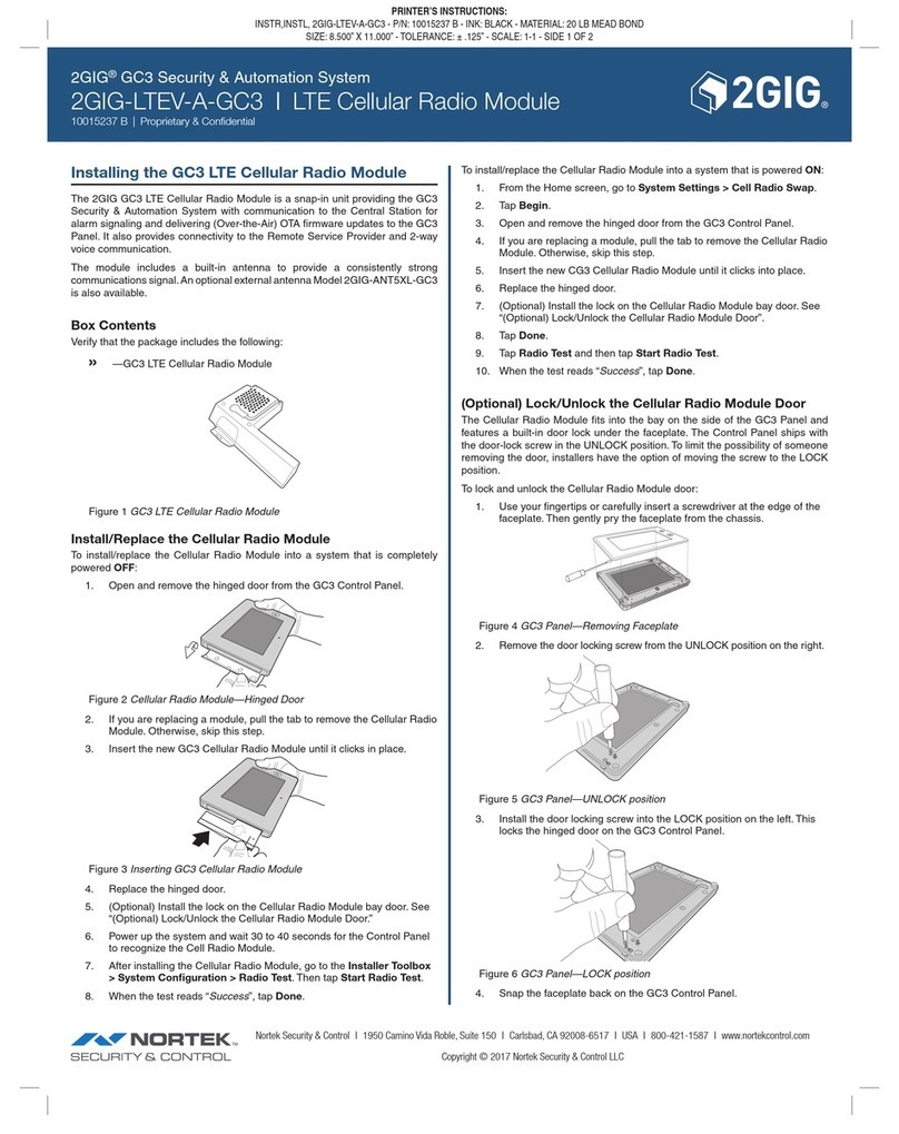
Copyright © 2016 Nortek Security &Control LLC.
1
Installation Instructions
Tamper
DIP SW1
1 2 3 4
OPT N/A
Test N/A
Intrnl MIC
Bypass
POWER
YEL GRN
BUS
BLK
COM
RED
AUX
BUS
AUX COM LED TMP Voice
(to panel)
Out In1 In2 In3
Message Box
Test
Spkr
LED1
Rec
Play
MIC1
VOICE MODULE
The 2GIG Vario Voice Module provides audible information about the status of the 2GIG Vario System, and enables any remote, touch-tone (DTFM) telephone to
act as a keypad for the system. When a system event occurs (such as an alarm activation) the Voice Module notifies a system user by calling a specified telephone
and playing a pre-recorded announcement.
NOTE: For instructions on how to program the Voice Module, see the 2GIG Vario System Installation Guide.
Installing the Voice Module
SW Description Usage
1 Omit Tamper Instead of a short with the TMP/COM terminal block
2 OPT N/A
3 Test
Connected in parallel to all output channels. It enables the user
to listed to all played messages using a speaker (at least 32
Ohm) connected between the Test Spkr and COM terminals.
4 Intern MIC
Select an external or internal microphone for recording
messages:
On: Enables recording messages from the microphone located
on the Voice Module board.
Off: Enables recording messages from a microphone located
on the 2GIG Vario Listen-in & Speak Module.
DIP Switches
2GIG® Vario System
2GIG Vario Voice Module
10012671 A

Nortek Security &Control | 1950 Camino VidaRoble, Suite 150 | Carlsbad, CA92008-6517 | USA | 800-421-1587 | www.nortekcontrol.com
Copyright © 2016 Nortek Security &Control LLC.
2
Wiring Diagram
Tamper
DIP SW1
1 2 3 4
OPT N/A
Test N/A
Intrnl MIC
Bypass
YEL GRN
BUS
BLK
COM
RED
AUX
BUS
AUX COM LED TMP Voice
(to panel)
Out In1 In2 In3
Message Box
Test
Spkr
COM
BLK
LEDTMP AUX
RED
AUDIO
OUT IN
Listen/Talk Unit
BUS
To Panel
Voice Module
When connecting the Listen-in & Talk Module to the Voice Module, it is recommended to use one of the following types of wires for the INand OUT connections:
Independently shielded wires: Used for Electro-Magnetically Noise Environment/Long Distance. The shield should be grounded (connected to the
COM terminal block).
Independently twisted paired wires: Used for Electro-Magnetically Unquiet Environment/Middle Distance. The second wire should be grounded
(connected to the COM terminal block).
Other types of wires: Can be used for Electro-Magnetically Silent Environment/Short Distance.
Wiring Notes:
Do not run wires close to power (110/230 VAC), high voltage wiring, or any communication lines.
Do not wrap or roll wires.
All unused wires should be grounded by connecting them to the COM terminal.
The maximum distance between each Listen-in & Talk Module and the Voice Module should not exceed 10 meters.
The maximum cable length for the Listen-in & Speak Module is 10 meters.
A maximum of 10 Listen-in & Speak Modules can be connected to the 2GIGVario System.
LED Indicators
Power: The Power LED indicates the status of communication between the Voice Module and the 2GIG Vario System panel.
Off: No voltage power from the main panel.
On: Normal communication with the panel BUS.
Slow Flash: The LED starts to flash 15 seconds after communication with the BUSis interrupted, or during installation mode.
Rec/Play: The Rec/Play LED indicates the status of communication between the Voice Module and the remote Follow-Me phone.
Off:No communication with the Follow-Me phone.
On: Follow-Me communication has been established.
Slow Flash: The Voice Module is in the process of clcalling the Follow-Me number.
2GIG® Vario System
2GIG Vario Voice Module
10012671 A

Nortek Security &Control | 1950 Camino VidaRoble, Suite 150 | Carlsbad, CA92008-6517 | USA | 800-421-1587 | www.nortekcontrol.com
Copyright © 2016 Nortek Security &Control LLC.
3
Connectors
AUX
COM
LED
TMP
VOICE
VOICE PLUG4
2GIG Vario Panel Voice Module
The Voice Module board contains the following connectors:
BUS (plug 1): Used to connect the Voice Module to the panel via the 4-wire BUS. The AUX (RED), COM (BLK), BUS (YEL), and BUS (GRN) terminals
are identical to the BUS connector and can be used for the same purpose.
VOICE (plug 2): Used to connect the Voice Module to the VOICE connector on the 2GIG Vario System main panel wia the supplied cable. This connector
transmits signals from the Voice Module to the telephone line during remote communication, and is essential for normal operation of the Voice Module.
Technical Specifications
Operating Voltage 13.8 VDC ± 10%
Current Draw 30 mA typical/70 mA maximum
Operating Temperature 0° C–70° C
Main Panel Connection Wire BUS, ≤ 300 m from main panel
User Operating
Telephone Control Commands
The 2GIGVario System enables you to operate the system from a remote touch-tone phone. by initiating a telephone call to or from the system. Interacting with
voice menus, you can remotely operate the system.
Receiving a Call
1. Pick up the phone.
2. Say "Hello" or press #. You will hear an event announcement message.
3. Choose an option from the Acknowledgment menu.
Acknowledgment Menu
When a system event occurs (such as an alarm activation) the Voice Module notifies a system user by calling a specified telephone and playing a pre-recorded
announcement. After the event message, the system announces the following options:
Operation Title Description Action (remotely by telephone)
Acknowledgment Message Confirms that you have received a message. The then system calls the next
Follow-Me number. Press 1.
Acknowledge and Stop All Dialing This option acknowledges the event and stops the system from calling the
other Follow-Me numbers to report the event.
Press 2and then enter the
appropriate code.
Acknowledge and Access the Operations
Menu
The Operations menu lists the available options for remotely operating your
system.
Press 3and then enter the
appropriate code.
Listen In and Talk This option enables you to perform bi-directional communication. Press 6, press 3, and then enter the
appropriate code.
Repeat the Event Message Press #.
Repeat the Acknowledge Menu Press *.
Acknowledgment Menu
2GIG® Vario System
2GIG Vario Voice Module
10012671 A

Nortek Security &Control | 1950 Camino VidaRoble, Suite 150 | Carlsbad, CA92008-6517 | USA | 800-421-1587 | www.nortekcontrol.com
Copyright © 2016 Nortek Security &Control LLC.
4
Calling the System
1. Dial the number of the premises.
If an answering machine is present at the premises: Let the line ring once, hang up, and call again.
If an answering machine is not in use at the premises: Wait until you hear a continuous tone, indicating that the system has answered the call.
2. After the tone, enter the 2-digit remote access code.
3. Enter your user code and press #.
4. Choose an option from the Operations menu.
Operations Menu
The Operations menu announces options and instructions on how to remotely use system functions. The options in the Operations menu vary according to system
status and your access rights.
The following is a list of remote operations options:
Description Action (remotely by telephone)
To set all partitions Press 1and press 1.
To set a selected partition Press 1, press 9, and then enter the partition number.
To un-set all partitions Press 2and press 2.
To un-set a selected partition Press 2, press 9, and then enter the partition number.
To change Zone Omit stats Press 3, enter the zone number, press #, and press 9.
To change Follow-Me numbers Press 5, enter the Follow-Me number, press #, and press 2.
Enter the new phone number, press #, and press 1.
To listen in to the premises Press 6and press 1.
To talk to the premises. Press 6and press 2.
To listen in and talk to the premises Press 6and press 3.
To record messages that are not included in the message bank (5 messages) Press 7and press 1–5.
To record an opening message Press 7and press 6.
To exit the system Press 0.
To return to the previous menu Press *.
To repeat the menu options Press #.
Operations Menu
2GIG® Vario System
2GIG Vario Voice Module
10012671 A

Nortek Security &Control | 1950 Camino VidaRoble, Suite 150 | Carlsbad, CA92008-6517 | USA | 800-421-1587 | www.nortekcontrol.com
Copyright © 2016 Nortek Security &Control LLC.
5
Regulatory Information
FCC Notice
This device complies with Part 15 of the FCC's Rules. Operation is subject to the following two conditions:
1. This device may not cause harmful interference, and
2. This device must accept any interference received, including interference that may cause undesired operation.
This equipment has been tested and found to comply with the limits for a Class B digital device, pursuant to Part 15 of the FCC Rules. These limits are designed to
provide reasonable protection against harmful interference in a residential installation.
This equipment generates, uses , and can radiate radio frequency energy and, if not installed and used in accordance with the instructions, may cause harmful
interference to radio communications. However, there is no guarantee that interference will not occur in a particular installation. If this equipment does cause
harmful interference to radio or television reception, which can be determined by turning the equipment off and on, the user is encouraged to try to correct the
interference by one or more of the following measures:
Reorient or relocate the receiving antenna.
Increase the separation between the equipment and receiver.
Connect the equipment into an outlet on a circuit different from that to which the receiver is connected.
Consult the dealer or an experienced radio/TV technician for help.
This product complies with FCC radiation exposure limits for an uncontrolled environment. Avoid operating this product at a distance less than 20 cm from the user.
NOTE: Any changes or modifications not expressly approved by the party responsible for compliance could void the user's authority to operate this
equipment.
Industry Canada (IC) Compliance
This device complies with Industry Canada license-exempt RSS standard(s). Operation is subject to the following two conditions: (1) this device may not cause
interference, and (2) this device must accept any interference, including interference that may cause undesired operation of the device.
Repairs to certified equipment should be made by an authorized Canadian maintenance facility designated by the supplier. Any repairs or alterations made by the
user to this equipment, or equipment malfunctions, may give the telecommunications company cause to request the user to disconnect the equipment.
Users should ensure for their own protection that the electrical ground connections of the power utility, telephone lines, and internal metallic water pipe system, if
present, are connected together. This precaution may be particularly important in rural areas.
Limited Warranty
This Nortek Security & Control product is warranted against defects in material and workmanship of two (2) years. This warranty extends only to wholesale
customers who buy direct from Nortek Security & Control LLC or through Nortek Security & Control LLC's normal distribution channels. Nortek Security & Control
LLC does not warrant this product to consumers. Consumers should inquire from their selling dealer as to the nature of the dealer's warranty, if any.
There are no obligations or liabilities on the part of Nortek Security & Control LLC for consequential damages arising out of or in connection with use or performance
of this product or other indirect damages with respect to loss of property, revenue, or profit, or cost of removal, installation, or reinstallation. All implied warranties for
functionality, are valid only until the warranty expires. This Nortek Security & Control LLC Warranty all other warranties expressed or implied.
All products returned for warranty service require a Return Authorization Number (RA#). Contact Returns at 1-855-546-3351 for an RA# and other important
details.
Inquiries
Direct all inquiries regarding this regulatory compliance statement to:
Nortek Security &Control
1950 Camino VidaRoble, Suite 150
Carlsbad, CA92008-6517
USA
800-421-1587
5IN2597
2GIG® Vario System
2GIG Vario Voice Module
10012671 A

THIS PAGE INTENTIONALLY LEFT BLANK
Other manuals for Vario
2
Table of contents
Other 2gig Technologies Control Unit manuals
Popular Control Unit manuals by other brands

Allen-Bradley
Allen-Bradley 1791-16BC manual

Technibel
Technibel CMHGV 2101 installation instructions

PG Drives Technology
PG Drives Technology SK78814/1 Technical manual

Honeywell
Honeywell RV260 Series installation instructions

Swegon
Swegon TBIQ-2-1-aa IQnomic Plus GOLD installation instructions

Schaudt
Schaudt LT 500 instruction manual

National Instruments
National Instruments NI 9861 operating instructions

HP
HP JC075A Product End-of-Life Disassembly Instructions

Nibe
Nibe SMO 40 Installer manual

Newport
Newport IMS300CC user manual

Webstone
Webstone E-X-P Series installation instructions

Wurth Elektronik
Wurth Elektronik Telesto-II user manual