360 Vision VisionDome User manual

360_VisionDome_Int_&_Ext_Inst_manual_V2.03_2006-03-14.doc Page 1 of 25
VisionDome Installation Manual
©360 Vision Technology Ltd Version 2.03
360 Vision Technology Ltd
VisionDome and Vision-i-Dome
Installation and Operating Manual

360_VisionDome_Int_&_Ext_Inst_manual_V2.03_2006-03-14.doc Page 2 of 25
VisionDome Installation Manual
©360 Vision Technology Ltd Version 2.03
Table of Contents
INTERNAL AND EXTERNAL Vision Domes....................................................3
CABLING .........................................................................................................3
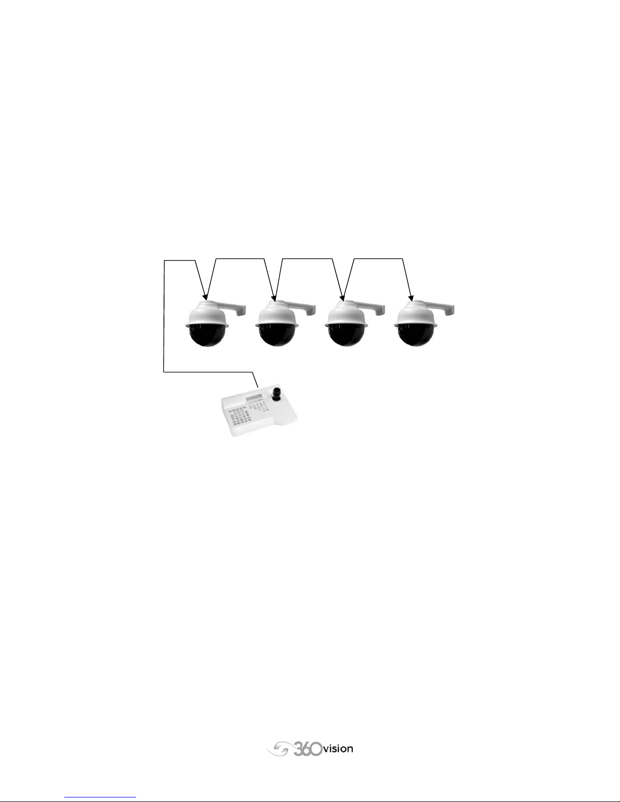
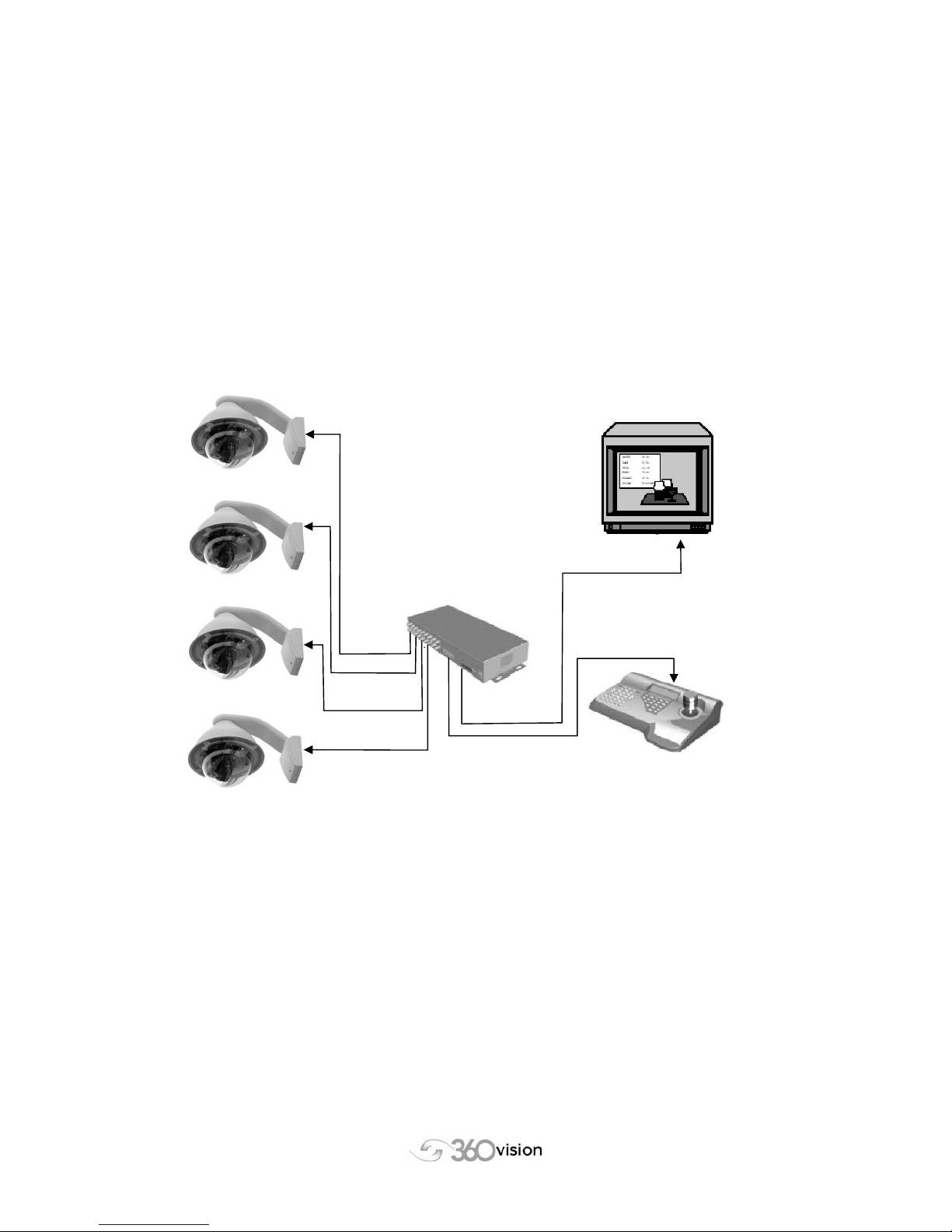
1. RS485 Configurations ...........................................................................3
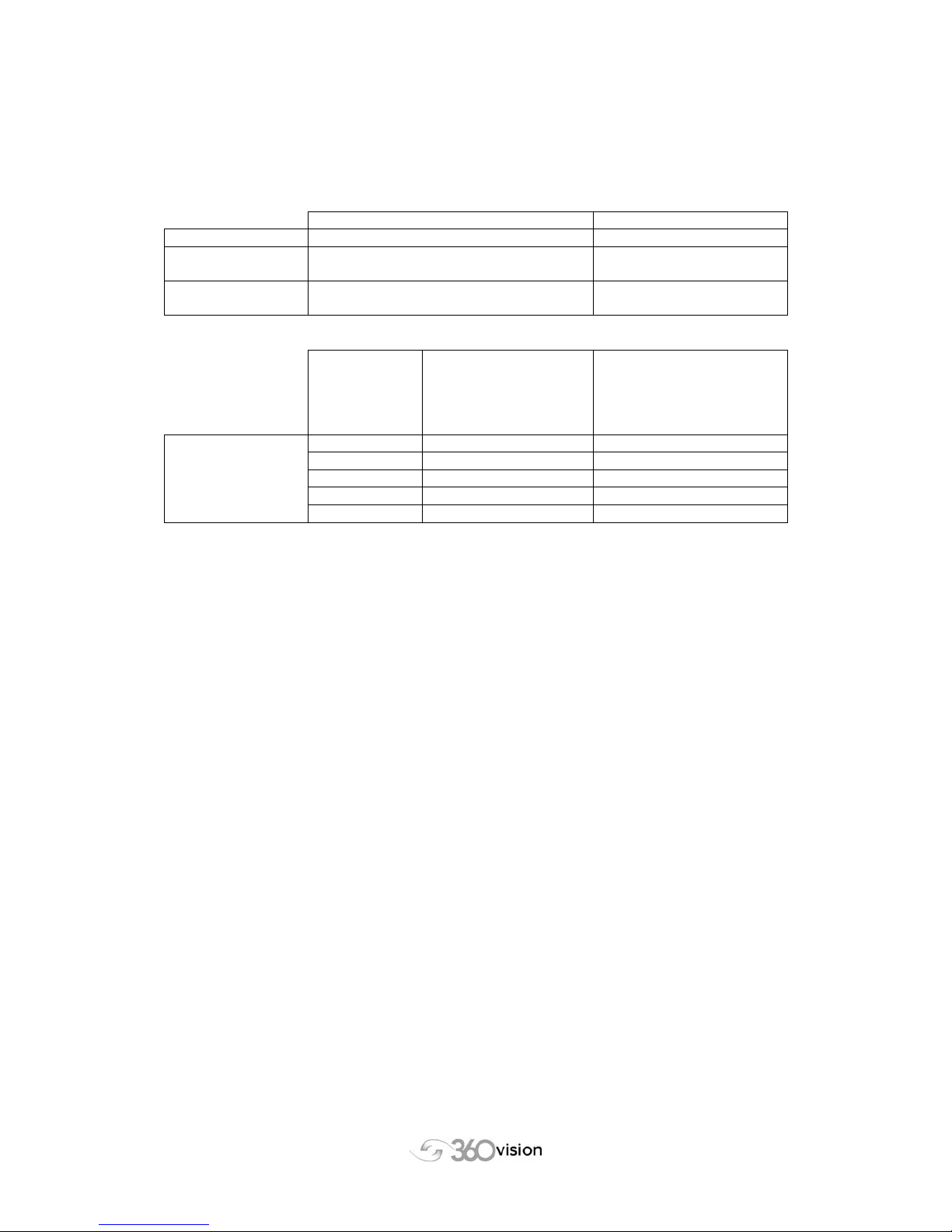
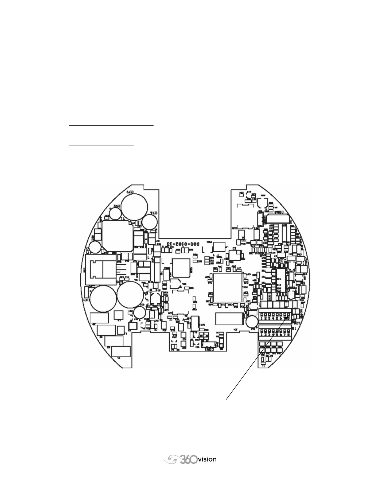
2. Address Settings for Twisted Pair Installations .....................................4
3. Vision-i-Domes On Screen Menus - advanced features. ......................4
4. Protocol Selection .................................................................................4
5. Cable & Wiring Requirements ...............................................................5
6. Coax Telemetry Settings & Control .......................................................6
7. 360 VisionDome Initialisation ................................................................7
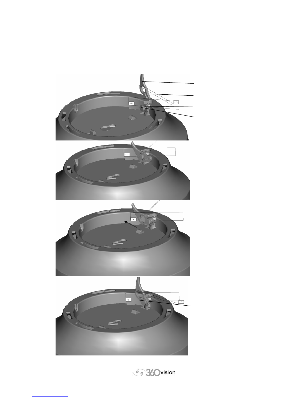
8. Click-On Lanyard Fixing........................................................................8
INTERNAL VisionDome and Vision-i-Dome (Mounting) ..................................9
9. Internal VisionDome Ceiling & Wall Mount Installation..........................9
10. Internal Corner Mount Installation (optional) .......................................12
11. Internal VisionDome False Ceiling Mount Installation .........................13
EXTERNAL VisionDome (Mounting) .............................................................15
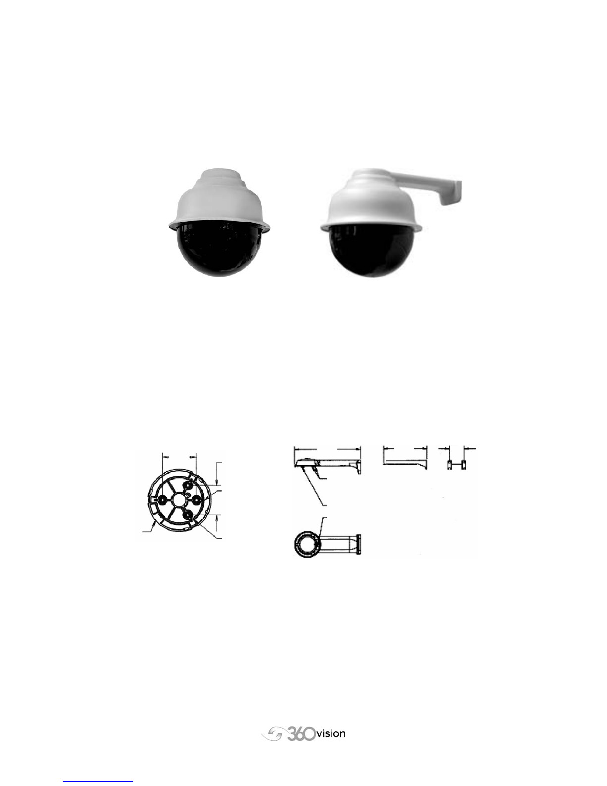
12. External VisionDome Wall Mount Installation......................................15
13. Exploded View of External VisionDome Wall Mount ...........................16
14. External VisionDome Soffit Mount Installation (optional).....................18
15. External Pole Mount Installation (optional)..........................................19
16. External Corner Mount Installation (optional) ......................................20
17. External Swan-neck Installation (optional) ..........................................21
EXTERNAL VisionDomes – Video Signal......................................................22
18. Adjustment of Gain and Lift .................................................................22
19. Remote Reset of VisionDome .............................................................22
VisionDome and Vision-i-Dome DATA...........................................................23
20. Technical Information..........................................................................23
21. Warranty & Safety Issues....................................................................25

360_VisionDome_Int_&_Ext_Inst_manual_V2.03_2006-03-14.doc Page 3 of 25
VisionDome Installation Manual
©360 Vision Technology Ltd Version 2.03
INTERNAL AND EXTERNAL Vision Domes.
CABLING
1. RS485 Configurations
The VisionDome is capable of being controlled by either COAX Telemetry (sometimes
referred to as ‘up the coax’ control) or via Twisted Pair RS485 Telemetry (TP)
The benefits of RS485 installations is that on long video runs, the degraded video signal can
be amplified using 3rd party line amplifiers without interfering with the control signal. Also,
using the correctly specified cabling specification (see section 5 - Cabling & Wiring
requirements) the installer can use the Daisy Chain method of installing multiple domes and
linking together.
Daisy Chain RS485
For correct operation, use a suitable cable (Overall Screened single Twisted Pair) and run to
each VisionDome. Cable the Data + and Data – to the first Dome and then back out onto the
next Dome. Ensure that all but the last VisionDome are left unterminated. Only the last
VisionDome should be terminated.
Do not connect the screen of the cable at both ends – Only connect the screen at the
control end
If installing more than 32 VisionDomes please use a TP Distribution Box to transmit
individual signals. Daisy Chaining can be used on each ‘output’

360_VisionDome_Int_&_Ext_Inst_manual_V2.03_2006-03-14.doc Page 4 of 25
VisionDome Installation Manual
©360 Vision Technology Ltd Version 2.03
2. Address Settings for Twisted Pair Installations
When controlling VisionDomes using Twisted Pair RS485, it is necessary to set the address
switches in the VisionDomes. Charts showing the address switch settings for the internal and
external VisionDomes are included with the Quick-Start-Guides.
For VisionDomes use 360-Quick-Start-Guide-VisionDome
For Vision-i-Domes use 360-Quick-Start-Guide-Vision-i-Dome
3. Vision-i-Domes On Screen Menus - advanced features.
Control of the advanced features of the VisionDomes and Vision-i-Domes can be done using
the menus in the VisionMatrix. When using Vision-i-Domes the On Screen Display (OSD)
menus can be used. A description of these menus is included in the
360-Quick-Start-Guide-Vision-i-Dome
4. Protocol Selection
Several different protocols can be used to control the VisionDomes. As the VisionDomes and
Vision-i-Domes have different features, the DIL switches MUST be set as described in the
appropriate Quick-Start Guides.
For VisionDomes use 360-Quick-Start-Guide-VisionDome
For Vision-i-Domes use 360-Quick-Start-Guide-Vision-i-Dome

360_VisionDome_Int_&_Ext_Inst_manual_V2.03_2006-03-14.doc Page 5 of 25
VisionDome Installation Manual
©360 Vision Technology Ltd Version 2.03
5. Cable & Wiring Requirements
SUITABLE CABLES
Cable type: Maximum Distances
Video: RG59BU (Poorer Quality) 250m
RG59BU (Good Quality),
RG11, CT125
1000m
RS485 Twisted
Pair:
Belden 9841, Belden 9842, Belden 8723,
Single Twisted Pair OS
3000m
Cable size Internal VisionDomes
and Vision-i-Domes
(No Heater)
Maximum Distances
(Using VDI-PSU)
External VisionDomes
(With Heater)
Maximum Distances
(Using VDE-PSU
or VDE-MALARM-EU)
Power 0.75 mm275m 30m
1.00 mm2100m 40m
1.25 mm2125m 50m
1.50 mm2150m 60m
2.50 mm2250m 100m
Distances are measured in metres
To ensure optimum VisionDome performance these parameters must be adhered to. Failure
to do so will invalidate the warranty.

360_VisionDome_Int_&_Ext_Inst_manual_V2.03_2006-03-14.doc Page 6 of 25
VisionDome Installation Manual
©360 Vision Technology Ltd Version 2.03
Vision-Dome
Vision-Dome
Vision-Matri
x
All Vision-Domes
controlled by coax-
telemetry.
(No RS485 TP daisy
chain is needed
)
Vision-Dome
Vision-Dome
Vision-Ke
y
board
6. Coax Telemetry Settings & Control
VisionDome can also be controlled also using ‘up the coax’ control signals from either a
VisionMatrix or a 3rd party controller capable of sending 360-Vision Coax Protocols.
No setup is necessary as all signals are sent direct to the camera associated with the
command, therefore negating the need to set an individual camera ID
Particular attention should be paid to the quality and strength of the Video Signal as any
discrepancies or degradation can lead to control signal issues.
360 Vision products can be mixed and matched in a single installation provided a
VisionMatrix is utilised

360_VisionDome_Int_&_Ext_Inst_manual_V2.03_2006-03-14.doc Page 7 of 25
VisionDome Installation Manual
©360 Vision Technology Ltd Version 2.03
7. 360 VisionDome Initialisation
When powering the VisionDome up for the first time, it may be necessary to just power up the
camera module and to not power up the Pan & Tilt mechanism – this therefore allows the
installation engineer adequate time to ensure all final cables and plugs are suitably inserted
This is called the halt initialisation during installation feature
Switch ‘S2’ position 8 is used to select the ‘halt initialisation during installation’ feature.
Switch in the default ‘off’ position
The dome will initialise shortly after turning on the power supply.
Switch in the ‘on’ position
The dome will delay the initialisation after turning on the power supply until:
1. The switch is turned off
2. The first pan, tilt or zoom telemetry is received
3. 10 minutes has elapsed
S2 position 8

360_VisionDome_Int_&_Ext_Inst_manual_V2.03_2006-03-14.doc Page 8 of 25
VisionDome Installation Manual
©360 Vision Technology Ltd Version 2.03
8. Click-On Lanyard Fixing.
The lanyard is supplied fastened inside the VisionDome external top cover. To fasten it to the
‘dome-inner’ pull the keyhole end downwards and attach it as described below:
Lanyard
Keyhole end
Stem
Button
Place keyhole over button
Pull lanyard so that the
slotted hole clicks into
place on the stem
In use, the keyhole will
rotate around the button but
will remain secure.

360_VisionDome_Int_&_Ext_Inst_manual_V2.03_2006-03-14.doc Page 9 of 25
VisionDome Installation Manual
©360 Vision Technology Ltd Version 2.03
INTERNAL VisionDome and Vision-i-Dome (Mounting)
9. Internal VisionDome Ceiling & Wall Mount Installation
NB :- When Handling the VisionDome, handle carefully so that the main electronics and
motor mechanism are not damaged.
Ceiling VisionDome Wall VisionDome
Step 1 – Attach bracketry
Please attach the appropriate bracketry to firm and solid surface (ceiling or wall) using
required fixings taking consideration of the weight (1.1kg).
Fixing to ceiling Fixing to wall
Feed the cables along the bracket.
Attach the supplied Clip-on Lanyard in order to secure the unit.
ORIENT DOME TO LINE-UP LOCKING TAB
WITH SLOT IN DOME BODY
TWIST BODY ONTO BRACKET
IMPORTANT – FIT LOCKING SCREW
LOCKING TAB
THE TWO PARTS OF THE WALL BRACKET ARE
SECURED BY FITTING THIS SCREW
246 161 55
mm mm mm
USE THREE SCREWS TO AFFIX DOME BASE TO CEILING
AFFIX LANYARD SECURELY TO CEILING
53
mm
46
mm
USE THE ‘KNOCKOUT’ SECTION
OF THE DOME BASE FOR SIDE
ENTRY OF CABLES
LOCKING SCREW
USES THIS SLOT
FOR ORIENTATION
USE CENTRAL HOLE
IN DOME BASE FOR
TOP ENTRY OF CABLES

360_VisionDome_Int_&_Ext_Inst_manual_V2.03_2006-03-14.doc Page 10 of 25
VisionDome Installation Manual
©360 Vision Technology Ltd Version 2.03
CLIP LANYARD ONTO DOME BODY
LOCKING
SCREW
214
mm
204 mm dia
TWIST BODY OF
VisionDome ONTO DOME
BASE OR WALL BRACKET
SECURE USING LOCKING
SCREW
TWIST ACRYLIC ONTO
DOME BODY
DOME BASE OR
WALL BRACKET
DOME BODY
ACRYLIC
Step 2 - Make connections
The internal dome connection board is located at the top of the dome and can be seen when
the dome is removed from the internal wall bracket or internal ceiling mount.
VisionDome (Internal) CONNECTION BOARD
Step 3 – Fit dome body
Align the security screw mount to the security screw socket on either the wall or ceiling mount
bracket – there is only one way to align and fix the top section. Once aligned, push up and
twist clockwise to ensure the 3 fixing lugs are correctly located as in Fig 4.
Data Connections:
If using RS485 twisted pair then connect to D+
and D-. (SCN is an unconnected terminal that
can be used to terminate the screen if required.)
Power Connections:
Connect 24Vac to 24VAC terminals
Video Connections:
For structured cable domes use VD+ and VD-
For COAX cable domes use:
Connect coax centre core to COAX VID
Connect the screen to COAX SCN

360_VisionDome_Int_&_Ext_Inst_manual_V2.03_2006-03-14.doc Page 11 of 25
VisionDome Installation Manual
©360 Vision Technology Ltd Version 2.03
Step 4 – Fit locking screw
Once twisted and locked, please insert 1 x M3 CSK screw (provided in fixing pack) and
securely tighten. This will ensure the rigidity as well as the security of the installation.
Step 5 – Attach acrylic
To attach the acrylic, line up the 3 gaps in the rim of the acrylic with the 3 lugs on the
VisionDome. Push and twist clockwise for a clean and easy fit.
Step 6 – Power up
After ensuring all fixings are secure, connect the VisionDome to the supplied PSU, power up
and proceed to programming. (See section 18 - Adjustment of Gain and Lift)

360_VisionDome_Int_&_Ext_Inst_manual_V2.03_2006-03-14.doc Page 12 of 25
VisionDome Installation Manual
©360 Vision Technology Ltd Version 2.03
10. Internal Corner Mount Installation (optional)
(The Internal Corner Mount Adapter is an optional extra accessory part)
For Internal Corner Mount please fasten the adapter to the corner of the walls using suitable
fixings, then follow the instructions for wall mounting.
An internal corner mount adapter is shown below.
Dimensions
3 0

360_VisionDome_Int_&_Ext_Inst_manual_V2.03_2006-03-14.doc Page 13 of 25
VisionDome Installation Manual
©360 Vision Technology Ltd Version 2.03
11. Internal VisionDome False Ceiling Mount Installation
NB :- When Handling the VisionDome, handle carefully so that the main electronics and
motor mechanism are not damaged.
False Ceiling VisionDome
Dimensions and bracketry required to install the VisionDome.
SPACE FOR CABLES ABOVE VisionDome 10mm (0.4”)
116mm
(
4.6”
)
99mm
(
4”
)
HOLE DIA 205mm
(
8”
)
250mm (9.9”)
TWIST OFF TOP PART
TO GAIN ACCESS TO
CONNECTIONS
FIT ACRYLIC BY
TWISTING CLOCKWISE
REMOVE ACRYLIC BY
TWISTING ANTI-
CLOCKWISE

360_VisionDome_Int_&_Ext_Inst_manual_V2.03_2006-03-14.doc Page 14 of 25
VisionDome Installation Manual
©360 Vision Technology Ltd Version 2.03
Step 1 – Cut hole and fit support plate.
Cut a hole in the false ceiling tile ensuring adequate weight considerations of the VisionDome
and support plate. Attach the supplied Lanyard in order to secure the unit.
Fixing to a false ceiling tile
Use the description for ‘wall and ceiling mounting’ for details of connections, attaching acrylic
and powering up.
THE HOLES IN THE
SUPPORT PLATE
CAN BE SECURED
TO THE BUILDING
STRUCTURE
USING 2mm DIA
BINDING WIRE
TWIST OFF TOP PART TO
GAIN ACCESS TO
CONNECTIONS USE CABLE TIE TO SECURE
CABLES TO THE HORIZONTAL BAR
AT THE TOP OF THE TOP PIECE
THE SUPPORT PLATE CAN
BE FITTED ABOVE THE
CEILING TILE OR IN
PLACE OF A 300mm X
600mm CEILING TILE
LANYARD IS SCREWED
TO THE HOLE IN TOP OF
DOME. SCREW FREE END
TO PART OF THE
STRUCTURE OF THE
BUILDING
CLAMP SWINGS OUT TO
SUPPORT DOME AS THE
SCREW IS TIGHTENED
(CLOCK-WISE)
WHEN SCREW IS LOOSENED
(ANTI-CLOCKWISE) THE CLAMP
SWINGS INWARDS TO ALLOW
THE CYLINDRICAL DOME BODY
TO PASS THROUGH THE HOLE IN
THE CEILING

360_VisionDome_Int_&_Ext_Inst_manual_V2.03_2006-03-14.doc Page 15 of 25
VisionDome Installation Manual
©360 Vision Technology Ltd Version 2.03
EXTERNAL VisionDome (Mounting)
12. External VisionDome Wall Mount Installation
NB :- When Handling the VisionDome, handle carefully so that the main electronics and
motor mechanism are not damaged
Mounting Bracketry for Wall Mounted External Domes
278
261
260
57
102
57
130

360_VisionDome_Int_&_Ext_Inst_manual_V2.03_2006-03-14.doc Page 16 of 25
VisionDome Installation Manual
©360 Vision Technology Ltd Version 2.03
EXTERNAL
ACRYLIC
CAPTIVE
SCREWS FOR
FIXING
EXTERNAL
ACRYLIC
13. Exploded View of External VisionDome Wall Mount
WALL
BRACKET
TOP COVER
LANYARD
CAMERA
ASSEMBLY
CAPTIVE
SCREWS
CAPTIVE SCREW
FOR FIXING INNER
COVER
INNER COVER
LANYARD

360_VisionDome_Int_&_Ext_Inst_manual_V2.03_2006-03-14.doc Page 17 of 25
VisionDome Installation Manual
©360 Vision Technology Ltd Version 2.03
Step 1 – Fix bracket to wall
Please attach the bracketry (wall) using required fixings taking consideration of the weight
(1.1kg for bracket, 2.5kg complete) and stability of the surface to which the bracket is to be
fixed.
Step 2 – Attach lanyard
Attach the supplied Lanyard in order to secure the Camera Assembly to the top cover
Step 3 – Make connections
The external dome connection board is located inside the top housing of the external dome. It
can be seen when the dome ‘inner’ is removed.
Step 3 – Fit camera assembly into top cover
Affix camera assembly into top cover by lining up the 4 screw fixings on the camera assembly
to the 4 mounting holes inside the top cover (there is only one correct way for the assembly to
insert) – guide rails allow the 4 screw positions to be correctly ‘guided’ onto the housing screw
posts
Step 4 – Fit inner cover to camera assembly
Fit inner cover to camera assembly by inserting captive screw in inner cover to the threaded
hole on the camera assembly.
Step 5 – Fit external acrylic
To attach the acrylic, first attach the Lanyard, line up the 4 captive screws with the holes in
the rim of the External VisionDome and fasten screws.
Step 6 – Power up
After ensuring all fixings are secure, connect the VisionDome to the supplied PSU, power up
and proceed to programming. (See section 18 Adjustment of Gain and Lift)
Connect the supplied
cable loom which is
present on the Dome Inner
to CON4
Heater connector CON2
(Already connected)
Video Connections:
For COAX cable domes use
VID and COAX SCN
Data Connections:
If using RS485 Twisted Pair
then Connect to D+ and D-
of CON 3
(SCR is an unconnected
terminal that can be
used to terminate the screen
if required).
Power Connections:
Connect 24Vac to
24VAC terminals
CON1
For structured cable domes
use
VID for VD+ and
SCR for VD-

360_VisionDome_Int_&_Ext_Inst_manual_V2.03_2006-03-14.doc Page 18 of 25
VisionDome Installation Manual
©360 Vision Technology Ltd Version 2.03
14. External VisionDome Soffit Mount Installation (optional)
(The Soffit adaptor is an optional extra accessory part)
NB :- When Handling the VisionDome, handle carefully so that the main electronics and
motor mechanism are not damaged
For Soffit installations, please use the Soffit adaptor and Gasket.
Mounting Soffit Adaptor for Soffit & Pole Mounted External Domes
GASKET
3 HOLES ON 68mm PCD
USE THESE HOLES FOR
FASTENING SOFFIT
ADDAPTOR TO CEILING.
AFFIX TOP COVER HERE
USING 3 SCREWS

360_VisionDome_Int_&_Ext_Inst_manual_V2.03_2006-03-14.doc Page 19 of 25
VisionDome Installation Manual
©360 Vision Technology Ltd Version 2.03
15. External Pole Mount Installation (optional)
(The External Pole Mount Adaptor is an optional extra accessory part)
For Pole mount installations, please follow the instructions for Wall mounting and add
the Pole mount adaptor to affix to the Pole.
External pole mounting of the dome is achieved through use of external wall mount housing
with a pole mount adapter.
A diagram of the pole mount adapter is shown below.
Fix the pole mount adapter to the pole with suitable fixings.
Fix the bracket to the pole adapter using appropriate fixings.
Draw the cabling through the adapter into the bracket’s fixing box. Withdraw the cable sealing
plug from the neck of the housing at the fixing box end. Make a small cut in the sealing plug
for each cable that will be drawn through the bracket, thread the cabling through the bracket
and push the plug back into place at the base of the housing neck.
Refit the cover to the bracket fixing box.
Make off all electrical connections onto the PCB located in the top of the housing.
Fix the black slotted inner dome cover to the side arm of the dome assembly.
Attach the lanyard from the dome inner assembly to the housing top cover.
Offer up the dome inner assembly and connect the multi-way connector into the socket
located on the PCB located in the top of the housing.
Locate the dome inner into the housing ensuring that the guide slots for the fixing screws slide
over the posts in the housing upper. Tighten the four Pozi pan fixing screws to secure the
dome inner to the housing.
Fix the outer acrylic by tightening the four captive screws.
SIDE VIEW
UNDERSIDE
VIEW
4 FIXING HOLES
ON 102 PCD
102
140
112
102

360_VisionDome_Int_&_Ext_Inst_manual_V2.03_2006-03-14.doc Page 20 of 25
VisionDome Installation Manual
©360 Vision Technology Ltd Version 2.03
16. External Corner Mount Installation (optional)
(The External Corner Mount Adapter is an optional extra accessory part)
For External Corner Mount please fasten the adapter to the corner of the walls using suitable
fixings, then follow the instructions for Wall mounting.
An external corner mount adapter is shown below.
Dimensions:
This manual suits for next models
1
Table of contents