Teradek Bolt DSMC2 User manual

NEED MORE HELP?
Support: http://support.teradek.com →Contains tips, information and all the latest firmware & software updates.
TERADEK SUPPORT STAFF: support@teradek.com or call 888−941−2111 ext2 (Mon−Fri 7am to 6pm PST)
PAIRING INSTRUCTIONS
Bolt DSMC2 is a zero delay
wireless video transmission
system designed to fit seamlessly
onto the back of RED DSMC2
cameras. Bolt transmits 1080p60
4:2:2 video at up to 500/1000/3000
ft line of sight over the unlicensed
5GHz band with less than 1ms
latency.
Confirm that PLEASE ACTIVATE PAIRING ON TX is displayed on receiver’s OLED
display (O) or the monitor.
Using the Menu joystick, select OK to finish pairing. This process takes up to a
minute. If pairing fails, power cycle the receiver and the transmitter and try again.
On the transmitter, use a paper clip (or similar) to press the Reset/Pairing
button (C). After a few seconds, Pairing: XXXXX... should be displayed on the
receiver’s OLED display or the monitor. If not, power cycle the receiver and the
transmitter, then try again.
Using the Menu joystick (N) on the receiver, navigate through the menus and
select Pairing.
2
4
5
3
E
K
B
Teradek regularly releases new firmware versions to improve performance, add new features, or to fix vulnerabilities.
Visit https://www.teradek.com to update your device with the latest firmware.
ZERO DELAY
WIRELESS
HD VIDEO
CONNECT AND POWER
Move the power switch (I) to the ON position.
C
1Turn on the Bolt transmitter and receiver. If the Bolt receiver does not have an OLED
display, connect a monitor to the receiver’s video output.
Place Bolt firmly against the back of the DSMC2 camera.
2
To remove Bolt, loosen the four captive screws and pull it off the back of the camera.
Tighten the four captive screws in a cross pattern ("X" pattern) using a 2.5mm hex wrench. DO NOT
OVER-TIGHTEN.
3
The Power status LED (E) will indicate power is present if a battery is connected to the DSMC2 Battery
Module or if power is provided via the DSMC2 camera. The camera will boot when the camera’s power
button is pressed. While the camera is booting, Bolt will also boot.
5
6
If using a DSMC2 Battery Module, place it firmly against the back of Bolt. Make sure the connector
in the front of the battery module aligns with the connector on the back of Bolt.
4
1
NOTE: If the Power status LED is on, but the camera does not boot, remove Bolt then re-attach, making
sure it’s properly seated. Always use an X pattern when tightening the M4 screws.
D
F
G
H
I
Bolt TX Bolt RX
A: RP-SMA connectors
B: Mini USB port
C: Reset/Pairing button
D: Wireless On/Off LED
E: Power status LED
F: Video status LED
G: Network status LED
H: Fault/Error
I: Power switch
J: Captive screws
K: HDMI output (opposite side)
L: Power input
M: 3G-SDI output
N: Menu joystick
O: OLED display
P: HDMI output
Q: NATO rail mount
Bolt 3000 XT -RX
FOR DSMC2
L
I
B
A
M
Q
C
P
O
N
A
J
Bolt TX
JJ
J
DEVICE OPERATION
GENERAL
• Keep the transmitter and the receiver at close range for 60 seconds after powering on the devices. This
allows them to scan for and select the best wireless channel.
• For best results when using multiple Bolt systems in the same area, place the transmitters and receivers
a few feet apart from each other.
•Operation of other wireless equipment may interfere with Bolt. For best results, separate other
wireless transmitters and receivers as much as possible.
Remove the protective MOD GUARD plate from the front of the Bolt DSMC2 by unscrewing
the four captive screws from the back (J).
7
Bolt DSMC2 - TX
DEVICE OPERATION (CONT.)
BOLT MANAGER
Bolt Manager allows you to configure, pair, and upgrade the Bolt system. Bolt Manager is available as software
for Mac and Windows at www.teradek.com/pages/downloads, or for purchase as a standalone device.
The following configuration settings are available:
• Select Region - Configure Bolt to comply with your region’s regulations governing use of the 5GHz spectrum.
• Select Frequencies - Configure the transmitter and receiver to use the same frequencies.
• Select TX Name- Modify the transmitter’s name to make it easily identifiable among other Bolt systems.
• Select Quality -Modify or balance the range and reliability of your signal. Select Maximum Range when other
sources of interference might be present, or Maximum Quality for complex, high contrast situations.
• Select Broadcast Mode - Increase transmission range and prevent multiple receivers from interfering with
each other when placed close to one another.
RECEIVER OSD/DISPLAY OPERATION
Status Screens - The status screens display useful information such as the current video resolution, frequency,
temperature, timecode, and the transmitter’s name and voltage. For receivers with an OLED display, use the Menu
Joystick to cycle through the status screens. For receivers without an OLED display, connect it to a monitor and
activate the OSD by depressing the Menu Joystick, then cycle through screens by pressing the button up or down.
Hide the status screen by pressing left.
Menu Operation - Bolt’s menu options allow you to customize and configure the device’s operation and settings
parameters. For receivers with an OLED display, launch then navigate through the menu using the Menu Joystick.
For receivers without an OLED display, press right on the Menu Joystick while the OSD is active. Exit from the
menu by pressing left.
• HDMI/SDI Out Format - Match the video source resolution by selecting Same as Input, or choose from the
resolutions listed.
• 3D LUT Settings (XT Only) -Select and apply a specific look.
• Spectrum Analyzer (XT Only) -Determine which frequencies are available to use.
• Test Pattern -Select a video format to output a test pattern. Remove the test pattern by pressing left on the
Menu Joystick.
• Pairing -Pair your receiver and transmitter. Once Pairing is selected, turn on the transmitter and use a
paper clip to hold the reset button (C) for one second and release. The warning and link LEDs will blink to
indicate that pairing is active.
• Video OSD Settings -By default, the OSD is displayed when the link is down. Hidden by default hides the OSD
until it is activated by the joystick, while Always show displays the OSD unless deactivated by the joystick.
• Display Settings (XT Only) -Configure the OLED display settings. Set the display to invert every 30 minutes
(lengthens the display life), or to dim or turn off after 10 seconds or 10 minutes.
• Keys/Unit Orientation (XT only) -Adjust the orientation of the device and joystick according to how the
receiver is mounted.
• Reset All Settings -Reset all configurable options to their factory defaults.
• Device Info -Displays the model and serial number.
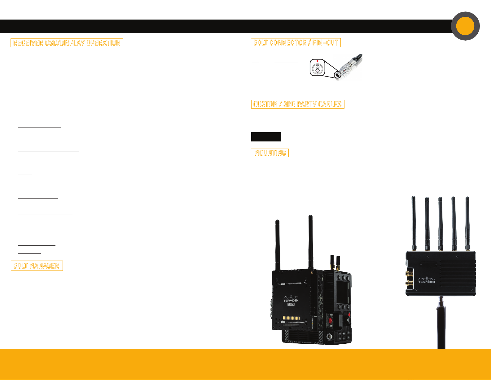
MOUNTING
• Mount the Bolt transmitter onto the back of a camera, keeping the antennas clear of DSMC2 any obstructions.
• Orient the transmitter and receiver antennas so they are parallel to each other.
• For best results, orient the transmitter antennas so each one has clear line−of−sight to the receiver.
Bolt receivers use a 2−pin power connector.
Pin Description
1* GND
2 +DC
BOLT CONNECTOR / PIN−OUT
* Pin 1 is closest to the red dot on the connector
Bolt DSMC2 transmitter
mounted on the back of
a camera
Bolt XT receiver
mounted vertically
on a light stand or
monitor
NEED MORE HELP?
Support: http://support.teradek.com →Contains tips, information and all the latest firmware & software updates.
TERADEK SUPPORT STAFF: support@teradek.com or call 888−941−2111 ext2 (Mon−Fri 7am to 6pm PST)
Teradek regularly releases new firmware versions to improve performance, add new features, or to fix vulnerabilities.
Visit https://www.teradek.com to update your device with the latest firmware.
CUSTOM / 3RD PARTY CABLES
CAUTION: Using a reverse polarity or improperly−constructed power cable can damage the product and
is not covered under warranty.
•Test the power cable polarity with ONLY the power cable connected to Bolt. Do not connect video cables.
• Check the power cable for shorts and proper grounding.
Other Teradek Camera Accessories manuals


Popular Camera Accessories manuals by other brands


RecorderGear
RecorderGear CG300 instruction manual

HIK VISION
HIK VISION 6 Inch Medium Speed Dome user manual

Rocket Fish
Rocket Fish RF-MONO70C Guía De Instalación Rápida

Panasonic
Panasonic DMW-VF1PP Service manual

Bioenno Power
Bioenno Power BLF-2420A user manual

Dometic
Dometic eStore Installation & setup guide


