Ganz GH-Fast Series User manual

\
1
Rev.18/04/2013
GH-Fast Series
INSTRUCTION MANUAL MANUALE D’ISTRUZUIONI INSTALLATIONSANLEITUNG
MANUEL D’INSTALLATION INSTRUKCJA OBSŁUGI MANUAL DE INSTRUCCIONES
GH-F12 outdoor housing 12VDC
custodia da esterno 12VDC
Caisson extérieur 12VDC
Außengehäuse 12VDC
obudowa zewnętrzna 12VDC
carcasa para exterior 12VDC
GH-F24 outdoor housing 24V~
custodia da esterno 24V~
Außengehäuse 24 V~
Caisson extérieur 24 V~
obudowa zewnętrzna 24V~
carcasa para exterior 24V~
GH-F230 outdoor housing 230V~
custodia da esterno 230V~
Außengehäuse 230 V~
Caisson extérieur 230 V~
obudowa zewnętrzna 230V~
carcasa para exterior 230V~
GH-FWM bracket and adjustable head for GH-F housing
staffa e snodo per GH-F
Halterung und Gelenkkopf für das GH-F-Gehäuse
Fixation et joint sphérique pour le caisson GH-F
wysięgnik z regulowanym przegubem do obudowy GH-F
carcasa GH-F con soporte y montura ajustable
GH-FW12 GH-F12, GH-FWM included
custodia da esterno 12VDC con staffa GH-FWM inclusa
GH-F12, einschließlich GH-FWM
GH-F12, y compris GH-FWM
obudowa GH-F12 z uchwytem GH-FWM w komplecie
carcasa para exterior 12VDC con GH-FWMincluido
GH-FW24 GH-F24, GH-FWM included
custodia da esterno 24V~ con staffa GH-FWM inclusa
GH-F24, einschließlich GH-FWM
GH-F24, y compris GH-FWM
obudowa GH-F24 z uchwytem GH-FWM w komplecie
carcasa para exterior 24V~ con GH-FWM incluido
GH-F230 GH-F230, GH-FWM included
custodia da esterno 230V~ con staffa GH-FWM inclusa
GH-F230, einschließlich GH-FWM
GH-F230, y compris GH-FWM
obudowa GH-F230 z uchwytem GH-FWM w komplecie
carcasa para exterior 230V~ con GH-FWM incluido
GH-FI Indoor housing without sunshield, GH-FWM included (no
sunshield)
custodia da interno con staffa GH-FWM inclusa (no
tettuccio)
Gehäuse für den Innenbereich ohne Sonnenschutzdach,
einschließlich GH-FWM (keinSonnenschutzdach)
Caisson pour uneutilisation interne sans pare-soleil,y
compris GH-FWM
wewnętrzna obudowa bez daszka z uchwytem GH-
FWM
carcasa para interior sin tapa de contrasol GH-
FWM incluido
GH-FWC12 GH-FW12 preassembled with hidden cables
protection
GH-FW12 con cavi a passaggio interno preassemblati
GH-FW12, vormontiert mit verstecktem
Kabelschutz
GH-FW12, prémonté avec protection de câble
dissimulée
Kompletna obudowa GH-FW12 obudowa z
ukrytym okablowaniem
GH-FW 12 preinstalado con proteccion de
cables ocultas
GH-FWC24 GH-FW24 preassembled with hidden cables
protection
GH-FW24 con cavi a passaggio interno preassemblati
GH-FW24, vormontiert mit verstecktem
Kabelschutz
GH-FW24, prémonté avec protection de câble
dissimulée
Kompletna obudowa GH-FW24 obudowa z
ukrytym okablowaniem
GH-FW24 preinstalado con proteccion de cable ocultas
GH-FWC230 GH-FW230 preassembled with hidden cables
protection
GH-FW230 con cavi a passaggio interno
preassemblati
GH-FW230, vormontiert mit verstecktem Kabelschutz
GH-FW230,prémontéavecprotection decâbledissimulée
Kompletna obudowa GH-FW230 obudowa z
ukrytym okablowaniem
GH-FW230 preinstalado con proteccion de cables
ocultas
GH-FG12 outdoor housing12VDCwith glasswindowoption
custodia da esterno 12VDC con finestra in vetro
e resistenza a vetro
Außengehäuse 12 VDC mit Glasfenster-Option
Caisson extérieur 12 VDC avec option de vitre en verre
Zewnętrzna obudowa 12VDC z opcjonalnym
oknem szklanym
carcas para exterior 12VDC con opcion de ventanilla
GH-FGW12 GH-FG12 including GH-FWM
GH-FG12 con staffa GH-FWM inclusa
GH-FG12, einschließlich GH-FWM
GH-FG12, y compris GH-FWM
Obudowa GH-FG12 z wysięgnikiem GH-FWM
GH-FG12 incluido con GH-FWM
READ CAREFULLY ALL INSTRUCTION AND WARNINGS REPORTED INTO THIS MANUAL BEFORE PROCEED ON HANDLING
AND USING OF THIS ITEM
LEGGERE ATTENTAMENTE QUESTO MANUALE PRIMA DI PROCEDERE ALL’INSTALLAZIONE DELLA CUSTODIA
LESEN SIE ALLE INSTALLATIONSANWEISUNGEN UND WARNHINWEISE IN DIESEM HANDBUCH, BEVOR SIE DIESES GERÄT
INSTALLIEREN UND NUTZEN.
LISEZ TOUTES LES INSTRUCTIONS D’INSTALLATION ET LES AVERTISSEMENTS CONTENUS DANS CE MANUEL AVANT
D’INSTALLER ET D’UTILISER CET APPAREIL
PRZECZYTAJ UWAŻNIE WSZYSTKIE UWAGI ORAZ OSTRZEŻENIA ZAWARTE W NINIEJSZEJ INSTRUKCJI OBSŁUGI PRZED
ROZPOCZĘCIEM INSTALACJI OBUDOWY
LEA CON CUIDADO TODAS LAS INSTRUCCIONES Y AVISOS INDICADOS EN ESTE MANUAL ANTES DE MANEJO Y INSTALACION
DE ESTE PRODUCTO.
Dust-tight and waterproof housing IP66

\
2
Rev.18/04/2013
FIG.1
90°
FIG.2
FIG.3
FIG.4
FIG.5
FIG.6
FIG.8
FIG.9

\
3
Rev.18/04/2013
CBC (Europe) S.r.l.
Ufficio di Milano
via E. Majorana,2
20834 - Nova Milanese (MB)
Italia
Tel. +39-0362-365079
Fax +039-0362-40012
e-mail tech_support@cbc-europe.it
CBC (EUROPE) GmbH.
Hansaallee, 191
40549 - Dusseldorf
Germany
Tel. +49-(0)211-530670
Fax +49-(0)211- 53067180
www.cbc-de.com
CBC (EUROPE) GmbH
7/8 Garrick Industrial Centre
Irwing Way
GB London NW9, 6AQ
Tel. +44-(0)208-732-3312
Fax +44-(0)208-202-3387
www.cbceurope.com
CBC (Poland) Sp.zo.o
Ul G. Morcinka,5 Paw6
01-496 Warszawa
Poland
Tel. +48-(0)22-638-4440
Fax +48-(0)22-638-4
CBC (AMERICA) Corp.
New York Office:
55 Mall Drive, Commack, NY 11725
Tel. (800) 422-6707
Fax. 631) 543-5426
California Branch Office:
20521 Earl Street, Torrance, CA 90503
Tel. (800) 888-0131
Fax. (310) 793-1506
FIG.7
FIG.8

\
4
Rev.18/04/2013
IMPORTANT SAFEGUARDS AND WARNINGS
This symbol indicates that dangerous voltage
constituting a risk of electric shock is present inside
of this unit.
This symbol indicates that there are important
instruction that have to be followed reported in the
manual to avoid risk to damage the products or
avoid hazardous risk to maintenance and service
personnel.
Prior to proceed on installation and operation of the product, please
read and understand carefully all the indication and instruction
reported on this manual.
Please take note and observe the following warnings:
1. Installation and servicing have to be done only by qualified
personnel and in compliant with local law.
2. Use only parts or subassembly indicated in this manual and
original by CBC. wrong choice of cables can affect to IP66
rating.
3. Installation must follow all local safety normative.
4. Use a thermo-magnetic all-pole switches with a minimum
contact gap of 3 mm, Install this device only where qualified
technical people could access it.
5. After maintenance or repair/replacement of parts, please
proceed in a check where should be assured that none of the
exposed parts have not been connected to main power or line
circuitry.
6. The installation method and materials have to be safe and
should be able to support minimum 4 times the weight of
camera/lens and housing and bracket weight combined.
7. After reading the manual, please preserve it for future needs
and use for servicing and maintenance operation.
PRODUCT DESCRIPTION
This GH-F housing series is a dust-tight and waterproof enclosures
designed to protect a CCTV camera/lens combination for indoor
and outdoor application.
The GH-F housing series includes hidden pre-cabled protected
versions to provide an easy and faster installation operation as
here under reported:
Model Power Input accepted
GH-FWC12: 12 VDC
GH-FWC24: 24 V~
GH-FWC230: 230 V~
The GH housings are also available without hidden pre-cabled
protected assembly. The models available are the following:
Model Power input accepted
GH-F12: 12 VDC
GH-F24: 24 V~
GH-F230: 230 V~
GH-FW12: 12 VDC
GH-FW24: 24 V~
GH-FW230: 230 V~
GH-FG12: 12 VDC
GH-FGW12: 12 VDC
GH-FI: -
Available accessories:
GH-FWM: Adjustable head and wall-mount bracket
GH-CM2: ceiling mount bracket
GH-SM: Spacer/wall- mount adapter for side running of cables
GH-PT: P/T plate adapter
GH-PAR: Pole mount adapter
GH-PS 230/24: Internal transformer 230 V~ / 24 V~
GH-PS 230/12: Internal power supply 230 V~ / 12 VDC
GH-PS 230/12H: Internal power supply 230 V~ / 12 VDC
GH-PS 24/12: Internal power supply 24 V~ / 12 VDC
GH-B24: 24V~ fun
GH-B12: 12VDC fun, use only regulated power sources to not
impugn fun MTBF
GH-VTA: alarm tamper system over coax cable
GH-TK1: tamper
GH-VSA: antishock system over coax cable
INSTALLATION AND OPERATION
Housing opening
WARNING! The GH-F230, GH-FW230 and
GH-FWC230 need a power supply at 230V~.
For safety reason, this model must be locked
with apposite polycarbonate screws also for
indoor application. This is requested to avoid
any accidental removal operation of the front
body part without the use of any tool that proof
the understanding of operation in progress and
the safety counter measures needed.
To achieve and open the housing body, the first operation are
related to the four polycarbonate screws locking the four swivel
spindles.
The top part of the housing can be pivoted on both sides
alternatively or completely removed operating by the special swivel
spindles; please unlock and open all swivel spindle to completely
remove the top housing part. (see FIG.1).
WARNING:the back side of the housing body
is destined to host power supply circuits and
terminal strip connection with presence of high
voltage. Before opening the housing, please,
switch off the line source.
For safety regulation, the part of the body hosting power circuits
must be accessed by tool.
Camera/lens assembling on housing
Coupling the camera and lens following respectively the indication
of their instruction manuals.
Due to the kind of lens used, camera or lens itself must be fixed on
housing plate. (see FIG.2).
We suggest to mount the camera/lens assembly as much close as
you can to the front window area (coincident with the camera/lens
mounting plate front borderline) considering the lens excursion in
case of zoom lens used.
Use the spacers provided for best axis front window view, if
needed. Please note that spacer with rubber insertions must be
installed in contact with the camera tripod in the way to reduce
possible camera vibrations.
Camera power supply
Connect the camera power input conductors to the “OUTPUT”
terminals of the power distribution board situated on the back side
of the housing (see FIG.3). Use “INPUT” terminals to connect main
power supply line. Please note that housing heater must be
connected only to appropriate power supply sources as previously
indicated in this manual
Warning: to avoid electrical hazardous, please,
check all the time the power supply source
voltage and camera requirements; in case of
discrepancies, use appropriate optional Ganz
power supply board to provide correct voltage
to camera unit.
In case of 12VDC models, use pin n°1 as
positive(+12V) and pin n°2 as negative (0V).
Power supply board installation
Please note that housing heater must be connected only to
appropriate power supply sources as previously indicated in this
manual; do not use GH-PS JP3 connector to power heater.
All outdoor GH-F housings are provided with a power distribution
board; always use this board to connect cameras and accessories.
Follow these steps:
1. Open the housing like above indicated.
2. Connect the camera power conductors to the appropriate
terminals “JP3” of power supply board.
3. Connect the main power supply input conductors to
appropriate “INPUT” terminals of distribution power board.
4. Connect “OUTPUT” terminals of distribution power board to
JP1 terminal of power supply board.
5. Fix the power supply board on spacers (see FIG.4).
In case you have not bought a pre-cabled version of GH-F housing,
the power supply line have to be provided by a three conductors
cable running through the central PG11 gland inside of the housing
or by the appropriate rubber provided for hidden cabling running
(see Hidden cable protection connection): the main power supply
conductors have to be connected to the appropriate terminal strips
in the following way:
Meaning Conductors color Terminal strip
MainPower IN Blue/Brown INPUT
Out Heater White HEATER
Out Camera OUTPUT
In addition, crimp the ground conductor to a ring terminal and fix it
to the point identified by Ground symbol by the M4 screw provided
on standard distribution board.
In case of 12VDC models, use pin n°1 as
positive(+12V) and pin n°2 as negative (0V).
ENGLISH

\
5
Rev.18/04/2013
FUN installation
Please note that housing heater must be connected only to
appropriate power supply sources as previously indicated in this
manual.
All outdoor GH-F housings are provided with a power distribution
board; if you need to install a GH-B12 fun, you need to substitute
this board with the once coming with the fun and you must provide
a stabilized (12VDC ±5%) power supply source.
Follow these steps:
1. Open the housing like above indicated.
2. Connect fun “JP1”terminal to AUX terminals of distribution
power supply board
3. connect the camera power conductors to “OUTPUT”
terminals of distribution power supply board.
4. Connect the main power supply input conductors to
appropriate “INPUT” terminals of distribution power board.
5. Connect “HEATER” terminals of distribution power board to
heater power supply conductors.
6. Fix the fun board on spacers located on upper part of the
housing.
In case you have not bought a pre-cabled version of GH-F housing,
the power supply line have to be provided by a three conductors
cable running through the central PG11 gland inside of the housing
or by the appropriate rubber provided for hidden cabling running
(see Hidden cable protection connection): the main power supply
conductors have to be connected to the appropriate terminal strips
in the following way:
Meaning Conductors color Terminal strip
MainPower IN Blue/Brown INPUT
Out Heater White HEATER
Out Camera OUTPUT
Out Fun AUX
In addition, crimp the ground conductor to a ring terminal and fix it
to the point identified by Ground symbol by the M4 screw provided
on standard distribution board.
In case of 12VDC models, use pin n°1 as
positive(+12V) and pin n°2 as negative (0V).
ZVA-TW100T/GH installation (only 230V~ versions)
Please note that housing heater must be connected only to
appropriate power supply sources as previously indicated in this
manual.
Follow these steps:
1. Open the housing like above indicated.
2. Connect “AUX” terminals of distribution power supply board
to the ZVA-TW100T/GH “230V~” terminals
3. connect the camera power conductors to “OUTPUT”
terminals of distribution power supply board in parallel.
4. Execute all remaining connections following indications of
ZVA-TW100T/GH manual.
5. Connect the main power supply input conductors to
appropriate “INPUT” terminals of distribution power board.
6. Fix the board on spacers located on bottom part of the
housing.
In case you have not bought a pre-cabled version of GH-F housing,
the power supply line have to be provided by a three conductors
cable running through the central PG11 gland inside of the housing
or by the appropriate rubber provided for hidden cabling running
(see Hidden cable protection connection): the main power supply
conductors have to be connected to the appropriate terminal strips
in the following way:
Meaning Conductors color Terminal strip
MainPower IN Blue/Brown INPUT
Out Heater White HEATER
Out Camera OUTPUT
ZVA-TW100T/GH AUX
In addition, crimp the ground conductor to a ring terminal and fix it
to the point identified by Ground symbol by the M4 screw provided
on standard distribution board.
GH-VTA installation
This device does not need any additional power supply; please fit
tamper and GH-VTA-T into their appropriate bays located in back
part of the housing (see FIG.5).
External connections
In case you have not bought a pre-cabled version of GH-F housing,
you will need to run a RG-59/U cable through one of the side
glands PG9, crimp it and connect to the camera. Verify the proper
water seal of the gland.
In case you need auxiliary connection cabling with camera station
(for example motorized zoom, tamper sensors, camera serial port),
run a multiconductors cable by one of the PG9 gland inside of the
housing.
Note that to open the PG shape, you need to force it using a screw
driver from outside part of the housing (see FIG.6)
Hidden cable protection connection
Also easy hidden cable protection is available following four quick
steps (see FIG.8):
1. force the hidden cabling shape, in the middle of the
housing, with a screw driver from outside part of the
housing.
2. properly fix bracket to the wall after having inserted cables
3. run cables inside adjustable head and fix it to the bracket
4. Insert cables in conic rubber, please note that only two
halls are opened by default and that you need to open the
third one in case you want to use additional cables.
5. fix housing on adjustable head only with provided screws
6. rubber will be automatically pressed on housing body
guaranteeing IP66 protection.
Please use only appropriate cables.
ENCLOSURE ASSEMBLY
Housing re-assembly
If this will be the latest operation to complete the housing body
closure, insert the desiccant bag (without plastic protection) inside
of the body before to proceed.
Close top body of the housing and fix it by the two opened swivel
spindles. Please turn the two safety screws for 90° matching locker
symbol and taking care that no cables are improperly running out
the housing.
Please assure all cables are correctly running inside the housing
before to close it and to not force housing to be closed.
Sunshield adjust
Sunshield can be moved to different positions unscrewing it. Please
note that you can find two additional shapes in the internal part of
the sunshield that you can drill to achieve an additional sunshield
excursion (see FIG.8).
Fixing of sunshield
Re-positioning of the sunshield on the holding points.
Insert the fixing screws and tie.
NOTES:every time you will open the housing, to avoid any
condensation effect, please change the desiccant bag with
a new one.
FIXING THE CAMERA STATION
The GH-F housing series is a light and medium/small enclosure for
CCTV camera/lens outdoor application. Nevertheless, especially
outdoor application can face severe environmental condition like
strong wind, heavy snow and ice in addition to a suitable load
bearing.
This require to the installer the maximum and careful attention on
fixing the camera station in the proper and safety way.
For example, to fix a camera station using GH-F housing series
with its own adjustable head and bracket on a wall, we suggest you
to use (4) steel fasteners with 12 mm external diameter and M6 bolt
with 10mm head.
Use as drilling mask a photocopy 1:1 of the latest page of this
manual reporting the bracket and cable running holes layout
positioning. NOTES
•GH-F housing provides two frontal screw threads for easy and
comfortable accessories installation (ex. IR lamps) and an
additional round shape that could be used for additional hidden
cabling or installation of air-filter (see FIG.9).
•In case you need lateral bracket cabling, you can operate as
indicated in FIG.10.
•Use only neoprene outdoor cables to guarantee IP66
protection rate: Video RG59 Ø6,1 mm, Alimentation Ø7 mm
(3x1 mmq)
•Lock safely high voltage cables and properly separate them by
low voltage ones
•When used/requested, cut ground cable longer than phase and
neutral
•This housing must not be considered a FIRE-ENCLOSURE; all
installed equipments must be compliant to EN 60950-1.
•PLEASE DO NOT CLEAN FRONTAL WINDOW WITH ANY
CHEMICAL PRODUCT; PLEASE USE ONLY WATER
TECHNICAL SPECIFICATIONS
Consumption:
GH-F230: < 40 mA
GH-F24: < 350 mA
GH-F12: < 700 mA
Maximum internal load: 20W (-20°C ~50°C)
IPrate: IP 66 (hidden or external cabling)
Operating Temperature: -20°C to +55°C (Max.internal load 17W)
Storage Temperature: -30°C to +55°C, RH 85% not
condensing
Vandal resistance: IK10 according to EN50102
Fire-self extinguish: V2 fire-self extinguish according
to UL94

\
6
Rev.18/04/2013
IMPORTANTI AVVISI DI PERICOLO E SICUREZZA
Questo simbolo indica che tensioni pericolose per
l’incolumità delle persone sono presenti all’interno del
prodotto.
Questo simbolo indica che le istruzioni riportate
devono essere seguite scrupolosamente per evitare il
rischio di danneggiamento del prodotto ed/o evitare
rischi di diversa natura ed entità per il personale che
maneggia il prodotto.
Prima di procedere all’uso ed installazione del prodotto, si prega di leggere
attentamente e capire completamente tutte le indicazioni e le istruzioni
riportate in questo manuale.
Si prega di prendere nota delle seguenti precauzioni ed avvisi di pericolo per
la salvaguardia di beni e persone:
1. L’uso e l’installazione del prodotto deve essere eseguita da personale
tecnico qualificato e nel rispetto delle leggi previste nel luogo dove viene
utilizzato il prodotto.
2. Utilizzare solo accessori e componenti indicati in questo manuale e
originali CBC. La scelta errata dei cavi può compromettere il grado IP66.
3. Ènecessario eseguire un installazione a regola d’arte secondo le regole
impiantistiche nazionali.
4. Deve essere previsto nell’impianto elettrico nell’edificio un dispositivo di
sezionamento onnipolare magnetotermico facilmente accessibile ed
avere una distanza tra i contatti di almeno 3mm.
5. Dopo operazioni di manutenzione o riparazione o integrazione del
prodotto con componenti opzionali, procedere ad un test di misurazione
che consenta di verificare la non esposizione di alcuna parte a tensioni di
alimentazione.
6. La destinazione d’uso del prodotto, i metodi di installazione ed i materiali
utilizzati per l’applicazione del prodotto devono rispettare tutte le norme di
sicurezza dei beni e delle persone che lo ospitano e pertanto, la
installazione deve garantire il supporto di almeno 4 volte il peso
complessivo dell’intero complesso di ripresa comprendendo in esso
anche il corpo telecamera/obiettivo.
7. Dopo l’utilizzo di questo manuale, se ne consiglia la custodia per future
necessità e consultazioni durante le operazioni di manutenzione o
modifiche.
DESCRIZIONE DEL PRODOTTO
La linea di prodotti GANZ GH-F è una famiglia di custodie a tenuta di polvere
ed acqua destinata alla protezione di complessi di ripresa TVCC in
applicazioni in ambienti interni ed in esterni.
La serie GH-F include versioni precablate con protezione meccanica totale
dei cavi. I kit disponibili in questa versione si differenziano per le tensioni di
alimentazione in ingresso, ossia:
Modello Ingresso di alimentazione
GH-FWC12: 12 VDC
GH-FWC24: 24 V~
GH-FWC230: 230 V~
Le custodie GH-F sono naturalmente disponibili anche in versione
classica e fornite senza cablaggio protetto, ossia:
Modello Ingresso di alimentazione
GH-F12: 12 VDC
GH-F24: 24 V~
GH-F230: 230 V~
GH-FW12: 12 VDC
GH-FW24: 24 V~
GH-FW230: 230 V~
GH-FG12: 12 VDC
GH-FGW12: 12 VDC
GH-FI: -
Accessori disponibili:
GH-FWM: snodo e staffa a parete
GH-CM2: staffa per installazione a soffitto
GH-SM: distanziale per installazione a muro ed uscita laterale dei cavi
GH-PT: adattatore per installazione a brandeggio
GH-PAR: adattatore a palo
GH-PS 230/24: trasformatore interno 230 V~ / 24 V~
GH-PS 230/12: alimentatore 230 V~ / 12 VDC
GH-PS 230/12H: alimentatore interno 230 V~ / 12 VDC
GH-PS 24/12: alimentatore interno 24 V~ / 12 VDC
GH-B24: ventola 24V~
GH-B12: ventola 12VDC utilizzare solo alimentazione 12VDC stabilizzata
GH-VTA: sistema di trasmissione allarme interruttore su cavo
coassiale
GH-TK1: interruttore
GH-VSA: sistema di trasmissione allarme anti-shock su cavo coassiale
INSTALLAZIONE ED UTILIZZO
Apertura custodia
ATTENZIONE!Le custodie GH-F230, GH-FW230
e GH-FWC230 richiedono un’alimentazione a
230V~. Per ragioni di sicurezza, questi modelli
devono sempre essere bloccati tramite le apposite
viti in poli-carbonato, anche se installate in interno. Il
tutto è richiesto al fine di evitare l’apertura
accidentale del corpo telecamera anteriore, senza
l’ausilio di utensili che comprovino la volontà di
aprire il corpo della custodia anche sul lato frontale
in possibile presenza di alimentazione.
Per aprire la custodia è necessario ruotare di 90° almeno 2 viti di blocco
prima agire sulle maniglie della custodia. La parte superiore della custodia
può essere rimossa completamente aprendo tutte le maniglie o solo
parzialmente aprendone solo due (vedi FIG.1).
ATTENZIONE: la parte posteriore della custodia
ospita la scheda di smistamento alimentazione e
morsettiere o l’alimentatore con presenza anche di
alta tensione: prima di rimuovere questa parte,
assicurarsi di avere tolto tensione alla linea di
alimentazione del complesso di ripresa.
Per le normative in essere riguardante la sicurezza fisica delle persone,
l’accesso ad aree di prodotti sottoposte ad alta tensione e quindi a rischio
degli operatori, devono essere protette in modo tale che l’accesso sia
possibile solocon l’ausilio di utensili o attrezzi (vedi FIG.1).
Installazione della camera/ottica
A seconda dell’accoppiamento camera/ottica prescelto sarà necessario
fissare alla slitta della custodia uno dei due dispositivi come (vedi FIG.2).
Vi suggeriamo di fissare la telecamera in modo che l’ottica risulti il più
vicino possibile alla finestra frontale della custodia considerando la
massima escursione dell’ottica in caso si utilizzino zoom motorizzati.
Utilizzare gli spessori forniti per ottimizzare l’asse ottico. Utilizzare lo
spessore dotato di gommino a contatto della telecamera per evitare
disorientamenti dovuti a vibrazioni.
Fornitura di alimentazione alla telecamera
Connettere i cavi di alimentazione della camera ai terminali “OUTPUT”
della scheda di distribuzione dell’alimentazione della custodia (vedi
FIG.3). Utilizzare i terminali “INPUT” per collegare l’alimentazione alla
custodia. Assicurarsi che il riscaldatore della custodia sia collegato ad una
fonte di alimentazione corretta come precedentemente indicato in questo
manuale. Attenzione: per evitare pericoli all’incolumità delle persone
che svolgono questa operazione ed all’eventuale
danneggiamento del prodotto e di quelli ospitati, verificare
preventivamente che l’alimentazione fornita dal circuito
montato all’interno della custodia sia coincidente a quello
richiesto dalla telecamera: in caso di incompatibilità,
rifornitevi del corretto trasformatore/alimentatore originale
GANZ che necessitate. In caso di modelli a 12VDC
utilizzare il pin n°1 come positivo (+12V) ed il pin n°2 come
negativo (0V).
Installazione della scheda interna di alimentazione
Assicurarsi che il riscaldatore sia collegato ad una sorgente di
alimentazione compatibile: non utilizzare i terminali JP3 del GH-PS JP3
per alimentare il riscaldatore.
Tutte le custodie da esterno GH-F sono fornite di scheda di distribuzione
dell’alimentazione; utilizzare sempre i terminali di questa scheda per
collegare gli accessori.
Seguire i seguenti passi:
1. Aprire la custodia.
2. Connettere i cavi di alimentazione della camera ai terminali JP3
del alimentatore.
3. Connettere la linea di alimentazione ai terminali “INPUT” della
scheda di distribuzione.
4. Connettere i terminali “OUTPUT” della scheda di distribuzione ai
terminali JP1 dell’alimentatore.
5. Fissare l’alimentatore (vedi FIG.4).
In caso si stia utilizzando una versione non precablata, l’alimentazione
deve essere fornita da un cavo tribolare attraverso il connettore PG11
centrale sul retro della custodia o attraverso il foro per il passaggio cavi
interni (vedi capitolo relativo) seguendo il seguente schema:
Significato Colore Terminale
Alimentazione primaria Blu/Marrone INPUT
Scaldiglia Bianco HEATER
Alimentatore OUTPUT
Collegare il cavo di terra all’apposito morsetto sulla scheda di
distribuzione identificabile dal simbolo di terra (vite M4).
In caso di modelli a 12VDC utilizzare il pin n°1
come positivo (+12V) ed il pin n°2 come negativo
(0V).
Installazione della ventola
Assicurarsi che il riscaldatore sia collegato ad una sorgente di alimentazione
compatibile. Tutte le custodie da esterno GH-F sono fornite di scheda di
distribuzione dell’alimentazione; utilizzare semprei terminali di questa scheda per
collegare gli accessori. In caso si utilizzi la ventola GH-B12, sostituire la scheda di
distribuzione originale con quella in dotazione all’accessorio. Per l’utilizzo della
custodia GH-B12 è necessario fornire una sorgente di alimentazione stabilizzata
(12VDC ±5%).
ITALIANO

\
7
Rev.18/04/2013
Attenersi alla seguente procedura:
1. Aprire la custodia.
2. Connettere i terminali “JP1” della ventola ai terminali AUX della
scheda di distribuzione.
3. Connettere i cavi di alimentazione della camera ai terminali
“OUTPUT” della scheda di distribuzione.
4. Connettere la linea di alimentazione ai terminali “INPUT” della
scheda di distribuzione.
5. Connettere i terminali “HEATER” della scheda di distribuzione ai
conduttori del riscaldatore.
6. Fissare la ventola sulle apposite torrette della parte superiore
della custodia.
In caso si stia utilizzando una versione non precablata, l’alimentazione
deve essere fornita da un cavo tribolare attraverso il connettore PG11
centrale sul retro della custodia o attraverso il foro per il passaggio cavi
interni (vedi capitolo relativo) seguendo il seguente schema:
Significato Colore Terminale
Alimentazione primaria Blu/Marrone INPUT
Scaldiglia Bianco HEATER
Camera/alimentatore OUTPUT
Collegare il cavo di terra all’apposito morsetto sulla scheda di distribuzione
identificabile dal simbolo di terra (vite M4).
In caso di modelli a 12VDC utilizzare il pin n°1
come positivo (+12V) ed il pin n°2 come negativo
(0V).
Installazione ZVA-TW100T/GH (solo versioni 230V~)
Assicurarsi che il riscaldatore sia collegato ad una sorgente di
alimentazione compatibile.
Attenersi alla seguente procedura:
1. Aprire la custodia.
2. Connettere i terminali “AUX” della scheda di distribuzione ai
terminali “230V~” dello ZVA-TW100T/GH “230V~”
3. Connettere i cavi di alimentazione della camera ai terminali
“OUTPUT” della scheda di distribuzione.
4. Eseguire le rimanenti connessioni seguendo le istruzioni del
manuale dello ZVA-TW100T/GH.
5. Connettere la linea di alimentazione ai terminali “INPUT” della
scheda di distribuzione.
6. Fissare lo ZVA-TW100T/GH sulle apposite torrette della parte
inferiore della custodia.
In caso si stia utilizzando una versione non precablata, l’alimentazione
deve essere fornita da un cavo tribolare attraverso il connettore PG11
centrale sul retro della custodia o attraverso il foro per il passaggio cavi
interni (vedi capitolo relativo) seguendo il seguente schema:
Significato Colore Terminale
Alimentazione primaria Blu/Marrone INPUT
Scaldiglia Bianco HEATER
Camera OUTPUT
ZVA-TW100T/GH AUX
Collegare il cavo di terra all’apposito morsetto sulla scheda di distribuzione
identificabile dal simbolo di terra (vite M4).
Installazione GH-VTA
Questo dispositivo non necessita di alimentazione; collocare il dispositivo
ed il camper come illustrato in figura (vedi FIG.5).
Connessioni esterne alla custodia
In caso non si intenda utilizzare il passaggio cavi protetto attraverso la
staffa della custodia, sarà necessario perforare le sagome circolare sul
retro della custodia ed utilizzare i PG in dotazione. Uno dei PG9 laterali
dovrà essere utilizzato per il cavo video RG-59/U mentre il secondo è
reso disponibile per connessioni ausiliarie non di potenza.
Utilizzare il PG11 centrale per il passaggio del cavo di alimentazione
adeguato. Forare la sagoma come indicato in figura FIG.6.
Connessioni nascoste protette alla custodia
La custodia GH-F nasce per fornire un passaggio cavi interno
protetto comodo e sicuro (vedi FIG.8):
1. forare la sagoma circolare posta al centro della custodia.
2. inserire i cavi all’interno della staffa e fissarla alla parete.
3. Inserire i cavi nello snodo e fissarlo alla staffa.
4. Inserire i cavi nel gommino conico in dotazione prestando
attenzione a forare il terzo passaggio in caso di necessità.
5. Fissare la custodia sullo snodo e stringere le 4 viti di fissaggio.
6. Il gommino verrà automaticamente guidato nell’apposito incavo
garantendo una tenuta IP66.
Utilizzare solo cavi conformi alle richieste.
CHIUSURA ED ASSEMBLAGGIO
Chiusura custodia
Se questa è l’ultima parte del corpo custodia che ne consentirà il
completo assemblaggio, prima di effettuarla, inserire un sacchetto
di sali desiccanti all’interno del corpo.
Chiudere la custodia agendo sulle leve precedentemente aperte e
ruotare di 90° le viti di sicurezza procedendo esattamente.
Assicurarsi di non forzare la chiusura della custodia e che tutti i
cavi sia ben alloggiati all’interno della custodia.
Fissaggio il tettuccio parasole
Il tettuccio parasole può essere spostato rimuovendo le due viti di
fissaggio. In caso le tre posizioni disponibili non garantiscano
un’escursione sufficiente, perforare le sagome poste all’interno del
tettuccio come indicato in figura 8.
Fissare il tettuccio nuovamente con entrambe le viti al termine
dell’operazione.
NOTA: ogni volta che aprite il corpo custodia, sostituite il sacchetto
di sali desiccanti per evitare effetti di condensa alla
richiusura per effetto di variazioni termiche.
FISSAGGIO DEL COMPLESSO DI RIPRESA
La serie di custodie GANZ GH_F è una linea di contenitori e supporti per
complessi di ripresa TVCC di piccole dimensioni e pesi contenuti, indicato
per applicazioni da interno ed esterno.
Tali caratteristiche non devono comunque far dimenticare all’installatore
delle condizioni atmosferiche che, specialmente in applicazioni da
esterno, possono modificare drasticamente le situazioni: la vela creata dal
profilo della custodia in condizioni di forte vento, il deposito di neve o la
formazione di ghiaccio e la capacità di sostentamento propriodel peso del
complesso di ripresa sono caratteristiche che trovano risposta nella
qualità di montaggio e fissaggio del complesso di ripresa.
Si richiede, quindi la massima attenzione per queste attività, svincolate
dalle caratteristiche intrinseche del prodotto. Per esempio, per fissare il
complesso di ripresa tramite la staffa di sostegno fornita, vi consigliamo di
utilizzare 4 tasselli in acciaio con diametro esterno 12mm abbinati a viti
con testa esagonale da 10mm e passo M6.
Per una corretta foratura della superficie di aggancio della staffa e del
passaggio cavi attraverso di essa, fotocopiate l’ultima pagina di questo
manuale ed utilizzatelo come maschera.
NOTE
•Le custodie GH-F sono dotate di due inserti metallici filettati nella
parte anteriore della custodia che possono essere utilizzati per
l’installazione di accessori esterni come ad esempio illuminatori
infrarossi. È resa inoltre accessibili una sagoma circolare aggiuntiva
che potrà essere utilizzata per un passaggio cavi addizionale o per
l’installazione di un filtro d’aria opzionale (vedi FIG.9).
•In caso si necessiti un’uscita laterale dei cavi dalla staffa
fissata a parete, si potrà operare come illustrato in FIG.10.
•Utilizzare solo cavi da esterno con guaina in neoprene per
garantire il grado di protezione IP66: cavo video RG59 Ø 6,1
mm, Alimentazione Ø 7 mm (3x1 mmq)
•Bloccare in modo sicuro i cavi ad alta tensione e separarli da
quelli a bassa tensione
•Quando utilizzato/previsto, tagliare il conduttore di terra in
modo che sia più lungo di quelli di fase e neutro
•Questa custodia non deve essere utilizzata come
INVOLUCRO-ANTIFUOCO; tutti i dispositivi installati al suo
interno devono rispondere alla normativa EN 60950-1.
•PULIRE LA FINESTRA FRONTALE SOLO CON ACQUA E
PANNO MORBIDO. NON UTILIZZARE ALCUN PRODOTTO
CHIMICO
SPECIFICHE TECNICHE
Consumo:
GH-F230: < 40 mA
GH-F24: < 350 mA
GH-F12: < 700 mA
Assorbimento massimo interno: 20W (-20°C ~50°C)
Grado IP: IP 66
Temperatura d’uso: -20°C to +55°C (ass.interno 17W)
Temperatura di stoccaggio: -30°C to +55°C, RH 85% non
condensante
Resistenza antivandalica: IK10 in accordo a EN50102
Autoestinguenza: Autoestinguenza V2 in accordo a
UL94

\
8
Rev.18/04/2013
WICHTIGE SICHERHEITS- UND WARNHINWEISE
Dieses Symbol zeigt gefährliche Spannungen im
Gerät an, die einen Stromschlag verursachen
können.
Dieses Symbol zeigt wichtige Anweisungen im
Handbuch an, die befolgt werden müssen, um
Schäden am Produkt und Gefahren für das
Wartungs- und Service-Personal zu vermeiden.
Bitte lesen und verstehen Sie sorgfältig alle Hinweise und Anweisungen in
diesem Handbuch, bevor Sie dieses Produkt installieren und bedienen.
Beachten Sie bitte die folgenden Warnhinweise:
1. Die Installation und Service-Arbeiten dürfen nur von qualifiziertem
Personal entsprechend den örtlichen Vorschriften durchgeführt werden.
2. Verwenden Sie nurOriginal CBC-Teile oder -Baugruppen, die in diesem
Handbuch angegeben werden. Falsch ausgewählte Kabel können die
Schutzklasse IP66 beeinflussen.
3. Die Installation muss allen örtlichen Sicherheitsvorschriften entsprechen.
4. Verwenden Sie einen Thermoschalter mit einem Kontaktabstand von
mindestens 3 mm. Installieren Sie den Schalter nur dort, wo er von
qualifiziertem technischen Personal bedient werden kann.
5. Prüfen Sie nach der Wartung oder Reparatur/Austausch von Teilen,
dass keine ungeschützten Teile mit der Netzspannung oder der
Netzinstallation verbunden sind.
6. Die Installationsart und die Materialien müssen sicher und in der Lage
sein, bis zum 4-fachen des Gewichts der Kamera mit Objektiv, des
Gehäusesund der Halterung zu tragen.
7. Bewahren Sie das Handbuch nach dem Lesen für eine zukünftige
Verwendung wie Service-und Wartungsarbeiten auf.
PRODUKTBESCHREIBUNG
Die Gehäuse der Serie GH-F sind staub- und wasserdicht und
geeignet, eine CCTV-Kamera mit Objektiv in einer Innen- und
Außenanwendung zu schützen.
Die Gehäuse-Serie GH-F beinhaltet auch Versionen mit einer
versteckten, geschützten Vorverkabelung, um eine einfache und
schnelle Installation zu gewährleisten wie im weiteren Verlauf
beschrieben:
Modell Eingangsspannung
GH-FWC12: 12 VDC
GH-FWC24: 24 V~
GH-FWC230: 230 V~
Die GH-Gehäuse sind auch ohne versteckter, geschützter
Vorverkabelung erhältlich. Folgende Modelle sind verfügbar:
Modell Eingangsspannung
GH-F12: 12 VDC
GH-F24: 24 V~
GH-F230: 230 V~
GH-FW12: 12 VDC
GH-FW24: 24 V~
GH-FW230: 230 V~
GH-FG12: 12 VDC
GH-FGW12: 12 VDC
GH-FI: -
Erhältliches Zubehör:
GH-FWM: Gelenkkopf und Wandarm
GH-CM2: Deckenmontagehalterung
GH-SM: Abstandhalter/Wandmontageadapterfür seitlichenKabelverlauf
GH-PT: P/T Schlittenadapter
GH-PAR: Mastmontageadapter
GH-PS 230/24: Eingebauter Trafo 230 V~ / 24 V~
GH-PS 230/12: Eingebaute Spannungsversorgung 230 V~ / 12 VDC
GH-PS230/12H:EingebauteSpannungsversorgung230V~/12 VDC
GH-PS 24/12: Eingebaute Spannungsversorgung 24 V~ / 12 VDC
GH-B24: 24 V~ Ventilator
GH-B12: 12 VDC -Ventilator, verwenden Sie nur geregelte Netzteile, um die
Lebensdauer des Ventilators nicht zu verkürzen
GH-VTA: Sabotageschutz-Alarmsystem über Koaxialkabel
GH-TK1: Sabotagekontakt
GH-VSA: Antischock-System über Koaxialkabel
INSTALLATION UND BEDIENUNG
Öffnen des Gehäuses
WARNUNG! Die Gehäuse GH-F230, GH-FW230 und
GH-FWC230 benötigen 230 V~ Netzspannung. Aus
Sicherheitsgründen müssen dieseModelle mit passenden
Kunststoffschrauben, auch bei Innenanwendungen,
verschlossen werden. Dies ist erforderlich, um ein
versehentliches Öffnen des vorderen Gehäuseteils ohne
Werkzeug zu verhindern, welches das Verständnis der
weiteren Bedienung und die Sicherheitsvorschriften
unterläuft.
Um das Gehäuse zu öffnen, müssen zunächst die vier Klappverschlüsse
beachtet werden, die mit vier Kunststoffschrauben gesichert sind.
Der obere Teil des Gehäuses kann durch diese Klappverschlüsse
zu beiden Seiten aufgeklappt oder vollständig entfernt werden; um
den oberen Teil des Gehäuses zu entfernen, müssen alle
Klappverschlüsse entsichert und geöffnet werden. (siehe Abb. 1)
WARNUNG: Die Unterseite des Gehäuses nimmt die
Schaltung für die Spannungsversorgung und die
Anschlussklemmen auf, an denen Netzspannung anliegt.
Schalten Sie vor dem Öffnen des Gehäuses die
Netzspannungab.
Aufgrund der Sicherheitsvorschriften darf am Gehäuseunterteil mit der
Schaltung für die Spannungsversorgung nur mit isoliertem Werkzeug
gearbeitet werden.
Montage der Kamera mit Objektiv im Gehäuse
Montieren Sie das ObjektiVDCuf die Kamera, indem Sie die Anweisungen in
den entsprechenden Handbüchern befolgen.
Je nach verwendetem Objektiv muss die Kamera oder das Objektiv selbst
auf dem Kameraschlitten des Gehäuses befestigt werden. (siehe Abb. 2)
Es wird vorgeschlagen, die Kamera/Objektiv-Einheit so nahe wie möglich an
das vordere Fenster zu montieren (so dass es sich in Höhe der Vorderkante
des Kameraschlittens befindet), wobei im Falle eines Zoom-Objektivs die
Bewegung des Objektivsberücksichtigt werden muss.
Verwenden Sie, falls erforderlich, für eine optimale Ausrichtung zum vorderen
Fenster die mitgelieferten Abstandhalter. Beachten Sie, dass dabei die
Abstandhalter mit Gummieinsätzen einen Kontakt zum Kamerastativ haben
müssen, um eventuelle Kameravibrationen zu reduzieren.
Spannungsversorgung der Kamera
Schließen Sie die Adern des Spannungsversorgungskabels an die Klemmen
„OUTPUT“ an, die sich auf der Anschlussplatine im unteren Gehäuseteil
befinden. Schließen Sie das Netzkabel an den Klemmen „INPUT“ an.
Beachten Sie, dass Gehäuseheizungen nur an geeignete Netzteile
angeschlossen werden dürfen, auf die vorne im Handbuch hingewiesen
wurde. Warnung: Um Gefahren durch elektrischen Strom zu
vermeiden, vergleichen Sie immer die Ausgangsspannung
des Netzteils mit der erforderlichen Spannung der Kamera;
verwenden Sie bei Unstimmigkeiten geeignete optionale
Spannungsversorgungsplatinen, um die Kamera mit der
richtigen Spannung zu versorgen.
Bei Modellen für 12 VDC ist Pin 1 positiv (+12 V) und Pin
2negativ (0V).
Installation der Netzteilplatine
Beachten Sie, dass Gehäuseheizungen nur an geeignete Netzteile
angeschlossen werden dürfen, auf die vorne im Handbuch
hingewiesen wurde; verwenden Sie für die Heizung nicht den
Anschluss GH-PS JP3.
Alle Außengehäuse vom Typ GH-F sind mit einer Anschlussplatine
ausgestattet; Schließen Sie die Kamera und Zubehör nur an diese
Platine an.
Befolgen Sie diese Anweisungen:
1. Öffnen Sie das Gehäuse wie oben beschrieben.
2. Schließen Sie die Spannungsversorgungsleitungen an die
entsprechenden Anschlüsse „JP3“ der Netzteilplatine an.
3. Schließen Sie das Netzspannungskabel an die entsprechenden
Anschlüsse „INPUT“ der Anschlussplatine an.
4. Verbinden Sie die Klemmen „OUTPUT“ der Anschlussplatine
mit den Klemmen „JP1“ der Netzteilplatine.
5. Befestigen Sie die Netzteilplatine auf Abstandhaltern (siehe
Abb. 4).
Bei der vorverkabelten Version des GH-F-Gehäuses muss ein dreiadriges
Spannungsversorgungskabel durch die zentrale PG11-Verschraubung oder
mit dem entsprechenden Gummi für die versteckte Verkabelung (siehe
versteckter Kabelschutzanschluss) in das Gehäuse geführt werden:
Schließen Sie die Adern des Spannungsversorgungskabels an die
entsprechenden Anschlüsse wie folgt an:
Bezeichnung Aderfarbe Anschluss
Netz IN Blau/Braun INPUT
Ausgang Heizung Weiß HEATER
Ausgang Kamera OUTPUT
Crimpen Sie zusätzlich eine Ringöse auf den Schutzleiter und
befestigen Sie ihn mit der mitgelieferten M4-Schraube auf der
Anschlussplatine an der Stelle, die mit dem Erde-Symbol
gekennzeichnet ist.
Bei Modellen für 12 VDC ist Pin 1 positiv (+12 V)
und Pin 2 negativ (0 V).
Installation des Ventilators
Beachten Sie, dass Gehäuseheizungen nur an geeignete Netzteile
angeschlossen werden dürfen, auf die vorne im Handbuch hingewiesen
wurde.
Alle Außengehäuse vom Typ GH-F sind mit einer Anschlussplatine
ausgestattet. Wenn Sie einen Ventilator vom Typ GH-B12 anschließen
DEUTSCH

\
9
Rev.18/04/2013
möchten, müssen Sie die vorhandene Platine durch die ersetzen, die
zusammen mit dem Ventilator geliefert wird, und eine stabilisierte
Spannungsquelle (12 VDC ±5%) zur Verfügung stellen.
Befolgen Sie diese Anweisungen:
1. Öffnen Sie das Gehäuse wir oben beschrieben.
2. Verbinden Sie die Klemmen „JP1“ des Ventilators mit den
Klemmen „AUX“ der Anschlussplatine.
3. Schließen Sie die Adern des Kamerakabels an die
Anschlüsse „OUTPUT“ der Anschlussplatine an.
4. Schließen Sie das Netzspannungskabel an die entsprechenden
Anschlüsse „INPUT“ der Anschlussplatine an.
5. Schließen Sie Adern des Heizungsanschlusskabels an die
Klemmen „HEATER“ der Netzteilplatine an.
6. Befestigen Sie die Platine des Ventilators auf den
Abstandhaltern im Gehäuseunterteil.
Bei der vorverkabelten Version des GH-F-Gehäuses muss ein
dreiadriges Spannungsversorgungskabel durch die zentrale PG11-
Verschraubung oder mit dem entsprechenden Gummi für die
versteckte Verkabelung (siehe versteckter Kabelschutzanschluss)
in das Gehäuse geführt werden: Schließen Sie die Adern des
Spannungsversorgungskabels an die entsprechenden Anschlüsse
wie folgt an:
Bezeichnung Aderfarbe Anschluss
Netz IN Blau/Braun INPUT
Ausgang Heizung Weiß HEATER
Ausgang Kamera OUTPUT
Ausgang Ventilator AUX
Crimpen Sie zusätzlich eine Ringöse auf den Schutzleiter und
befestigen Sie ihn mit der mitgelieferten M4-Schraube auf der
Standard-Verteilerplatine an der Stelle, die mit dem Erde-Symbol
gekennzeichnet ist.
Bei Modellen für 12 VDC ist Pin 1 positiv (+12 V)
und Pin 2 negativ (0 V).
Installation des ZVA-TW100T/GH (nur 230 V~ -Versionen)
Beachten Sie, dass Gehäuseheizungen nur an geeignete Netzteile
angeschlossen werden dürfen, auf die vorne im Handbuch
hingewiesen wurde.
Befolgen Sie diese Anweisungen:
1. Öffnen Sie das Gehäuse wie oben beschrieben.
2. Verbinden Sie die Klemmen „AUX“ der Netzteil-Verteilerplatine
mit den Klemmen „230V~“ des ZVA-TW100T/GH.
3. Schließen Sie die Adern des Kamerakabels an die Anschlüsse
„OUTPUT“ der Netzteil-Verteilerplatine parallel an.
4. Stellen Sie alle weiteren Verbindungen entsprechend des
Handbuches des ZVA-TW100T/GH her.
5. Schließen Sie das Netzspannungskabel an die entsprechenden
Anschlüsse „INPUT“ der Anschlussplatine an.
6. Befestigen Sie die Platine auf den Abstandhaltern im
Gehäuseunterteil.
Bei der vorverkabelten Version des GH-F-Gehäuses muss ein dreiadriges
Spannungsversorgungskabel durch die zentrale PG11-Verschraubung oder
mit dem entsprechenden Gummi für die versteckte Verkabelung (siehe
versteckter Kabelschutzanschluss) in das Gehäuse geführt werden:
Schließen Sie die Adern des Spannungsversorgungskabels an die
entsprechenden Anschlüsse wie folgt an:
Bezeichnung Aderfarbe Anschluss
Netz IN Blau/Braun INPUT
Ausgang Heizung Weiß HEATER
Ausgang Kamera OUTPUT
ZVA-TW100T/GH AUX
Crimpen Sie zusätzlich eine Ringöse auf den Schutzleiter und befestigen Sie
ihn mit der mitgelieferten M4-Schraube auf der Standard-Verteilerplatine an
der Stelle, die mit dem Erde-Symbol gekennzeichnet ist.
Installation des GH-VTA
Dieses Gerät benötigt keine zusätzliche Spannungsversorgung. Befestigen
Sie den Sabotagekontakt und das GH-VTA-T in den entsprechenden
Einbuchtungen im Gehäuseunterteil (siehe Abb. 5).
Externe Anschlüsse
Wenn nicht die vorverkabelte Version des GH-F-Gehäuses eingesetzt wird,
muss ein Kabel vom Typ RG-59/U durch eine der seitlichen PG9-
Verschraubungen geführt, gecrimpt und an die Kamera angeschlossen
werden. Prüfen Sie die Verschraubung auf Dichtigkeit gegenüber Wasser.
Wenn eine weitere Verkabelung zur Kamera erforderlich ist (z.B. Motor-
Zoom, Sabotagesensoren, serielle Schnittstelle der Kamera), führen Sie ein
mehradriges Kabel durch eine der seitlichen PG9-Verschraubungen in das
Gehäuse.
Beachten Sie, dass Sie zum Öffnen des vorgestanzten Lochs für die
Verschraubung einen Schraubendreher von außen am Gehäuse ansetzen
müssen (siehe Abb. 6).
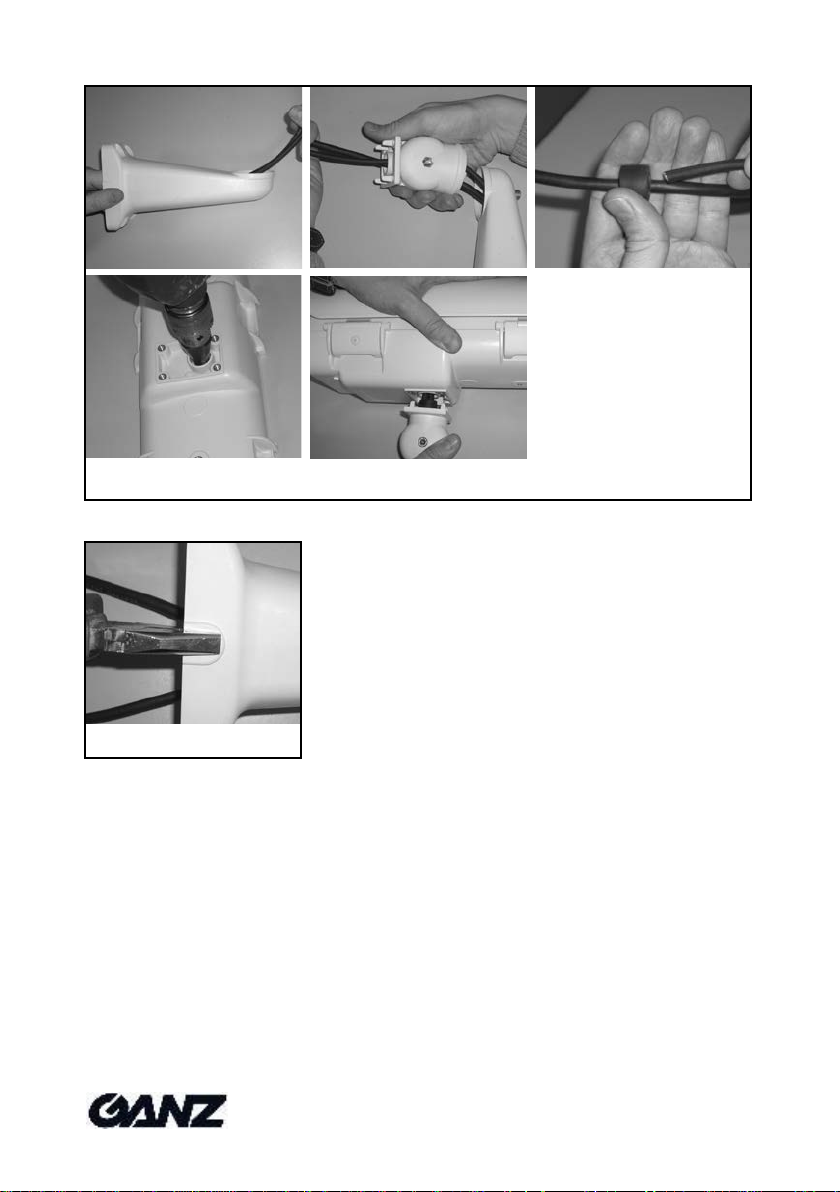
Versteckter Kabelschutzanschluss
Auch ein einfacher versteckter Kabelschutzanschluss kann mit vier
schnellen Schritten vorgenommen werden (siehe Abb. 8):
1. Öffnen Sie in der Mitte des Gehäuses das vorgestanzte Loch für die
versteckte Verkabelung mit einem Schraubendreher, den Sie von außen
am Gehäuseansetzenmüssen.
2. Befestigen Sie den Wandarm sorgfältig an der Wand, nachdem Sie die
Kabel durchgeführt haben.
3. Führen Sie die Kabel durch den Gelenkkopf und befestigen Sie ihn auf
der Halterung.
4. Führen Sie die Kabel durch konische Gummis und beachten Sie, dass
ab Werk nur zwei Löcher geöffnet sind und Sie ein drittes Loch öffnen
müssen, wenn weitere Kabel erforderlich sind.
5. Befestigen Sie das Gehäuse nur mit den mitgelieferten Schrauben auf
den Gelenkkopf.
6. Das Gummi wird automatisch an das Gehäuse gepresst, wobei die
Schutzklasse IP66 eingehalten wird.
ZUSAMMENBAU DES GEHÄUSES
Gehäuse zusammenbauen
Wenn dies der letzte Schritt vor dem Zusammenbau des Gehäuses ist, legen
Sie einen Antikondensationsbeutel (ohne Kunststoffschutz) in das Gehäuse,
bevor Sie fortfahren.
Schließen Sie das Oberteil des Gehäuses und befestigen Sie es mit den
beiden Klappverschlüssen. Drehen Sie bitte die beiden Sicherungsschrauben
um 90°, so dass sie auf das Verschluss-Symbol zeigen und passen Sie dabei
auf, dass keineKabel aus dem Gehäuse herausragen.
Prüfen Sie, dass sich alle Kabel korrekt im Gehäuse befinden, bevor Sie es
vorsichtig schließen.
Einstellen des Sonnenschutzdachs
Das Sonnenschutzdach kann in verschiedene Positionen bewegt
werden, ohne es zu lösen. Beachten Sie, dass sich zwei weitere
vorgestanzte Öffnungen im Inneren des Sonnenschutzes befinden,
die Sie aufbohren können, um eine weitere Auslenkung des
Sonnenschutzdachs zu erreichen (siehe Abb. 8).
Befestigung des Sonnenschutzdachs
Positionieren des Sonnenschutzdachs an den Haltepunkten.
Schrauben Sie es mit den Befestigungsschrauben fest.
ANMERKUNGEN: Wechseln Sie bei jedem Öffnen des Gehäuses
den Antikondensationsbeutel, um ein Kondensieren von
Feuchtigkeit zu verhindern.
BEFESTIGUNG DES KAMERAGEHÄUSES
Die leichten und eher schmalen Gehäuse der Serie GH-F sind für
Außenanwendungen mit CCTV-Kameras mit Objektiv geeignet. Trotzdem
können gerade bei Außenanwendungen widrige Umgebungsbedingungen
wie starker Wind, viel Schnee und Eis bei einer geeigneten tragenden
Verbindung auftreten.
Dies erfordert vom Installateur ein Maximum an Sorgfalt und Vorsicht bei der
sicheren Befestigung desKameragehäuses.
Es wird z.B. vorgeschlagen, eine Kamera in einem Gehäuse der Serie GH-F
mit dem zugehörigen Gelenkkopf und einem Wandarm mit 4 Stahl-
Unterlegscheiben mit einem Außendurchmesser von 12 mm und M6-
Schraubenmit 10 mm-Kopf zu befestigen.
Nehmen Sie als Bohrschablone eine 1:1-Fotokopie der letzten Seite dieses
Handbuchs, auf der sich die Positionen der Löcher für die Halterung und die
Kabeldurchführungen befinden.
ANMERKUNGEN
•Die GH-F-Gehäuse verfügen über zwei vordere Gewindelöcher für die
einfache und komfortable Installation von Zubehör (externe IR-Strahler)
und einer weiteren Lochvorstanzung, die für eine zusätzliche versteckte
Verkabelung oder für die Installation eines Luftfilters benutzt werden kann
(siehe Abb. 9).
•Falls eine seitliche Verkabelung an der Halterung notwendig ist, können
Sie diese wie in Abb. 10 gezeigt vornehmen.
•Benutzen Sie nur außen taugliches, neopren Kabel, damit der IP66
Schutzgrad garantiert werden kann: Video RG59Ø6,1 mm, Netzkabel
Ø7 mm (3x1 mmq)
•Befestigen Sie das Spannungskabel korrektund trennen Sie diese von
den Niederspannungskabel.
•Wenn benötigt/benutzt, muß das Erdungskabel länger sein als der
Neutralleiter und die Phase.
•Dieses Gehäuse muß nicht feuerfest sein, das installierte Equipment
muß der Norm EN 60950-1entsprechen.
•Bitte reinigen Sie die Glassfläche nur mit Wasser; Benutzen sie, zur
Reinigung keinechemischenProdukte,.
Technische Daten
Verbrauch:
GH-F230: < 40 mA
GH-F24: < 350 mA
GH-F12: < 700 mA
Maximale Innere Verbrauch: 20W (-20°C to +50°C)
IP-Klasse: IP 66 (hidden or external cabling)
Umgebungstemperatur: -20°C to +55°C (17W Maximale
Innere Verbrauch)
Speichertemperatur: -30°C ~ +55°C, RH 85% nicht
kondensierend
Vandale Widerstand: IK10 entsprechend EN50102
Feuerselbst löschen aus: V2 entsprechend UL94

\
10
Rev.18/04/2013
AVERTISSEMENTS DE SÉCURITÉ IMPORTANTS
Ce symbole indique des tensions dangereuses
contenues dans l’appareil pouvant entraîner des
électrocutions.
Ce symbole signalise des instructions importantes
contenues dans le manuel qui doivent être
observées pour éviter les dommages au niveau du
produit et des dangers pour le personnel
d’entretien et de service.
Veuillez lire attentivement et intégrer toutes les informations et instructions de
ce manuel avant d’installer et de manipuler ce produit.
Veuillez respecter les avertissements suivants :
1. Les travaux d’installation et de service ne doivent être effectués que par
un personnel qualifié selon les prescriptions locales.
2. N’utilisez que les pièces ou les composants CBC originaux indiqués
dans ce manuel. Des câbles mal choisis peuvent avoir une influence sur
la classe de protection IP66.
3. L’installation doit être conforme à toutes les prescriptions de sécurité
locales.
4. Utilisez un commutateur thermomagnétique commutant tous les pôles
avec un écart des contacts de 3 mm minimum. Installez le commutateur
uniquement à un endroit où il puisse être manipulé par un personnel
technique qualifié.
5. Contrôlez après tout entretien ou réparation/remplacement de pièces
qu’aucune pièce non protégée ne se trouve en contact avec la tension
de secteur ou l’installation électrique.
6. Le type d’installation et les matériaux doivent être sûrs et doivent être en
mesure de supporter jusque 4x le poids de la caméra, de l’objectif, du
caisson et de la fixation.
7. Conservez ce manuel après l’avoir lu dans pour toute utilisation ultérieure
lors de travaux de service et d’entretien par ex.
DESCRIPTION DU PRODUIT
Les caissons de la série GH-F sont étanches et hermétiques et
conviennent parfaitement à protéger une caméra CCTVDCvec
objectif pour une application en intérieur ou en extérieur.
Les caissons de la série GH-F sont également disponibles en
versions avec un précâblage dissimulé et protégé afin de permettre
une installation simple et rapide telle que décrite comme suit :
Modèle Tension à l’entrée
GH-FWC12 : 12 VDC
GH-FWC24 : 24 V ~
GH-FWC230 : 230 V ~
Les caissons GH sont également disponibles sans précâblage
dissimulé et protégé. Les modèles suivants sont disponibles :
Modèle Tension à l’entrée
GH-F12 : 12 VDC
GH-F24 : 24 V ~
GH-F230 : 230 V ~
GH-FW12 : 12 VDC
GH-FW24 : 24 V ~
GH-FW230 : 230 V ~
GH-FG12 : 12 VDC
GH-FGW12 : 12 VDC
GH-FI : -
Accessoires disponibles :
GH-FWM : Rotule et support mural
GH-CM2 : Fixation de montage au plafond
GH-SM : Ecarteur/adaptateur de montage au mur pour un cheminement de
câblage latéral
GH-PT : Adaptateur de rail P/T
GH-PAR : Adaptateur de montage sur mât
GH-PS 230/24 : Transformateur intégré 230 V~ / 24 V~
GH-PS 230/12 : Alimentation en tension intégrée 230 V~/ 12 VDC
GH-PS230/12H: Alimentationentensionintégrée230 V CA/ 12VDC
GH-PS 24/12: Alimentation en tension intégrée 24 V ~ / 12 VDC
GH-B24 : Ventilateur 24 V ~
GH-B12: Ventilateur 12 VDC , utilisez uniquement des blocs d’alimentation
stabilisés, pour ne pas raccourcir la durée de vie du ventilateur
GH-VTA : Système d’alarme anti-sabotage par câble coaxial
GH-TK1 : Contact anti-sabotage
GH-VSA : Système anti-choc par câble coaxial
INSTALLATION ET COMMANDE
Ouverture du caisson
ATTENTION ! Les caissons GH-F230, GH-FW230
et GH-FWC230 nécessitent une tension de réseau
de 230 V ~. Pour des raisons de sécurité, ces
modèles doivent être fermés par le biais de vis en
plastique appropriées, même pour une utilisation
en intérieur. Cela est nécessaire pour éviter toute
électrocution lors de l’ouverture sans outils de la
partie avant du caisson et pour respecter les
prescriptions de sécurité.
Pour ouvrir le caisson, considérer tout d’abord les quatre étriers de
fermeture qui sont sécurisés avec quatre vis en plastique.
Les étriers de fermeture permettent de soulever la partie
supérieure du caisson des deux côtés ou de la retirer
complètement ; pour retirer la partie supérieure du caisson,
déverrouiller et ouvrir tous les étriers de fermeture. (voir fig. 1)
AVERTISSEMENT : Le côté inférieur du caisson
contient la commutation pour l’alimentation en
courant et les bornes de raccordement au niveau
desquelles passe la tension. Couper le courant
avant d’ouvrir le caisson.
Pour des raisons de sécurité, il est impératif de travailler avec des
outils isolés au niveau de la partie inférieure du caisson comportant
la commutation de l’alimentation en courant.
Montage de la caméra équipée d’un objectif dans le caisson
Monter l’objectif sur la caméra en suivant les instructions
contenues dans les manuels correspondants.
Selon l’objectif utilisé, la caméra ou l’objectif doit être fixé sur le rail
de caméra même du caisson. (voir fig. 2)
Nous recommandons de monter le bloc caméra/objectif le plus près
possible de la vitre avant (de manière à ce qu’il se trouve à hauteur
du rebord avant du rail de caméra). Dans le cas d’un objectif à
zoom, il est nécessaire de prendre en compte les déplacements de
l’objectif.
Utiliser le cas échéant les écarteurs contenus dans la livraison pour
une orientation optimale par rapport à la vitre avant. Veiller à ce
que les écarteurs à inserts en caoutchouc entrent en contact avec
le trépied de la caméra pour réduire d’éventuelles vibrations de la
caméra.
Alimentation en tension de la caméra
Raccorder les brins du câble d’alimentation de tension aux bornes
« OUTPUT » qui se trouvent sur la platine de raccordement dans la
partie inférieure du caisson. Raccorder le bloc d’alimentation aux
bornes « INPUT ». Veiller à ce que les chauffages de caissons
soient uniquement raccordés aux blocs d’alimentation conformes
mentionnés au début du manuel (voir fig. 3).
Avertissement : pour éviter tout danger provenant
du courant électrique, toujours comparer la tension
de sortie du bloc d’alimentation avec la tension
nécessaire de la caméra ; utilisez en cas de
divergences des platines d’alimentation en tension
optionnelles appropriées pour alimenter la caméra
avec la tension correcte.
Pour les modèles de 12 VDC Pin 1 est positif
(+12 V) et Pin 2 est négatif (0 V).
Installation de la platine de réseau
Veiller à ce que les chauffages de caissons soient uniquement
raccordés aux blocs d’alimentation conformes mentionnés au début
du manuel ; ne pas utiliser le raccord GH-PS JP3 pour le
chauffage.
Tous les caissons extérieurs de type GH-F sont équipés d’une
platine de raccordement ; raccorder la caméra et les accessoires à
cette platine uniquement.
Suivre les instructions suivantes :
1. Ouvrir le caisson comme décrit plus haut.
2. Raccorder toutes les conduites d’alimentation en tension aux
raccords correspondants « JP3 » de la platine du bloc
d’alimentation.
3. Raccorder le câble de tension de réseau aux raccords
correspondants « INPUT » de la platine de raccordement.
4. Raccorder les bornes « OUTPUT » de la platine de
raccordement avec les bornes « JP1 » de la platine du bloc
d’alimentation.
5. Fixer la platine de réseau sur des écarteurs (voir fig. 4).
En ce qui concerne la version précâblée du caisson GH-F, un
câble d’alimentation de tension à trois brins doit être amené à
travers le vissage central PG11 ou avec un caoutchouc approprié
pour câblage dissimulé (voir raccordement à câblage dissimulé)
dans le caisson : raccorder les brins du câble d’alimentation en
tension aux raccordements correspondants comme suit :
Désignation Couleur du brin Raccord
Réseau IN Bleu/Brun INPUT
Sortie chauffage Blanc HEATER
Sortie caméra OUTPUT
Monter en supplément un œillet sur le conducteur de protection et
le fixer avec la vis M4 fournie avec la livraison sur la platine de
raccordement à l’endroit marqué par le symbole de mise à la terre.
Pour les modèles de 12 VDC Pin 1 est positif
(+12 V) et Pin 2 est négatif (0 V).
FRANÇAIS

\
11
Rev.18/04/2013
Installation du ventilateur
Veiller à ce que les chauffages de caissons soient uniquement
raccordés aux blocs d’alimentation conformes mentionnés au début
du manuel.
Tous les caissons extérieurs de type GH-F sont équipés d’une
platine de raccordement. Si vous souhaitez raccorder un ventilateur
de type GH-B12, il vous faudra remplacer la platine présente par
celle livrée avec le ventilateur et mettre à disposition une source de
tension stable (12 VDC ±5%).
Suivre les instructions suivantes :
1. Ouvrir le caisson comme décrit plus haut.
2. Raccorder les bornes « JP1 » du ventilateur avec les bornes
« AUX » de la platine de raccordement.
3. Raccorder les brins du câble de la caméra aux raccords
« OUTPUT » de la platine de raccordement.
4. Raccorder le câble de tension de réseau aux raccordements
correspondants « INPUT » de la platine de raccordement.
5. Raccorder les brins du câble de raccordement du chauffage
aux bornes « HEATER » de la platine du bloc d’alimentation.
6. Fixer la platine du ventilateur sur les écarteurs dans la partie
inférieure du caisson.
En ce qui concerne la version précâblée du caisson GH-F, un
câble d’alimentation de tension à trois brins doit être amené à
travers le vissage central PG11 ou avec un caoutchouc approprié
pour câblage dissimulé (voir raccordement à câblage dissimulé)
dans le caisson : raccorder les brins du câble d’alimentation en
tension aux raccordements correspondants comme suit :
Désignation Couleur du brin Raccord
Réseau IN Bleu/Brun INPUT
Sortie chauffage Blanc HEATER
Sortie caméra OUTPUT
Sortie ventilateur AUX
Monter en supplément un œillet sur le conducteur de protection et
le fixer avec la vis M4 fournie avec la livraison sur la platine
standard de distribution à l’endroit marqué par le symbole de mise
à la terre.
Pour les modèles de 12 VDC Pin 1 est positif
(+12 V) et Pin 2 est négatif (0 V).
Installation du ZVA-TW100T/GH(uniquement pour les versions 230 V ~)
Veiller à ce que les chauffages de caissons soient uniquement
raccordés aux blocs d’alimentation conformes mentionnés au début
du manuel.
Suivre les instructions suivantes :
1. Ouvrir le caisson comme décrit plus haut.
2. Raccorder les bornes «AUX » de la platine de distribution de
l’alimentation avec les bornes « 230V~» du ZVA-TW100T/GH.
3. Raccorder parallèlement les brins du câble de la caméra aux
raccordements « OUTPUT » de la platine de distribution de
l’alimentation.
4. Etablir tous les autres raccordements conformément au manuel
d’utilisationduZVA-TW100T/GH.
5. Raccorder le câble de tension de réseau aux raccordements
correspondants «INPUT » de la platine de raccordement.
6. Fixer la platine sur les écarteurs dans la partie inférieure du caisson.
En ce qui concerne la version précâblée du caisson GH-F, un
câble d’alimentation de tension à trois brins doit être amené à
travers le vissage central PG11 ou avec un caoutchouc approprié
pour câblage dissimulé (voir raccordement à câblage dissimulé)
dans le caisson: raccorder les brins du câble d’alimentation en
tension aux raccordements correspondants comme suit :
Désignation Couleur du brin Raccord
Réseau IN Bleu/Brun INPUT
Sortie chauffage Blanc HEATER
Sortie caméra OUTPUT
ZVA-TW100T/GH AUX
Monter en supplément un œillet sur le conducteur de protection et
le fixer avec la vis M4 fournie avec la livraison sur la platine
standard de distribution à l’endroit marqué par le symbole de mise
à la terre.
Installation du GH-VTA
Cet appareil ne nécessite pas d’alimentation supplémentaire. Fixer le contact
de sabotage et le GH-VTA-T dans les fentes correspondantes de la partie
inférieure du caisson (voir fig. 5).
Raccordements externes
Si la version précâblée du caisson GH-F n’est pas utilisée, un câble de type
RG-59/U doit être amené à travers l’un des vissages latéraux PG9, serti, puis
raccordé à la caméra. Contrôler l’étanchéité des vissages.
Si un câblage supplémentaire vers la caméra est nécessaire (par ex. zoom
motorisé, détecteurs de sabotage, interface sérielle de la caméra), amener un
câble à plusieurs brins à travers l’un des vissages latéraux PG9 dans le
caisson.
Veiller à appliquer un tournevis sur l’extérieur du caisson pour l’ouverture du
trou pré-perforé pour le vissage (voir fig. 6).
Raccordement dissimulé de la protection de câble
Même un raccordement de protection de câble dissimulé simple peut être
entrepris en quatre étapes rapides :
1. Ouvrir au milieu du caisson le trou pré-perforé prévu pour le
câblage dissimulé avec un tournevis qu'il faudra appliquer sur
l'extérieur du caisson (voir fig. 7).
2. Fixer soigneusement la fixation murale au mur après avoir fait
passer les câbles.
3. Amener les câbles à travers la rotule et la fixer sur le support.
4. Amener les câbles à travers les caoutchoucs coniques. Noter
que seuls deux trous sont ouverts lors de la livraison, il faudra
donc ouvrir un troisième trou si des câbles supplémentaires
sont nécessaires.
5. Fixer le caisson sur la rotule uniquement avec les vis fournies
(voir fig. 9).
6. Le caoutchouc est pressé automatiquement contre le caisson ;
la classe de protection IP66 est maintenue.
MONTAGE DU CAISSON
Monter le caisson
Si cette étape est la dernière avant le montage du caisson, placer
un sachet anti-condensation (sans plastique) dans le caisson avant
de continuer.
Fermer la partie supérieure du caisson et le fixer avec les deux
étriers de fermeture. Tourner les deux vis de fixation de 90°, de
manière à ce qu'elles pointent vers le symbole de verrouillage et
veiller à ce qu’aucun câble ne sorte du caisson.
Contrôler que tous les câbles sont placés correctement dans le
caisson avant de le refermer soigneusement.
Réglage du pare-soleil
Le pare-soleil peut être déplacé dans plusieurs positions sans qu’il
soit nécessaire de le détacher. Noter que deux autres ouvertures
préperforées se trouvent à l’intérieur du pare-soleil que vous
pouvez perforer pour atteindre un déplacement supplémentaire du
pare-soleil (voir fig. 8).
Fixation du pare-soleil
Positionner le pare-soleil aux points de fixation.
Le visser avec les vis de fixation.
REMARQUES : Remplacer le sac anti-condensation lors de
chaque ouverture du caisson pour éviter une condensation
de l’humidité.
FIXATION DU CAISSON
Les caissons légers et assez étroits de la série GH-F conviennent à
des applications en extérieur avec des caméras CCTV à objectif.
Néanmoins, une utilisation en extérieur peut résulter en des
environnements de travail difficiles comme par exemple du vent
fort, beaucoup de neige et de la glace pour un raccord de support
approprié.
Cela nécessite de la part du monteur un maximum de précautions
et d’attention pour une fixation sûre du caisson de caméra.
Nous vous recommandons par ex. de fixer une caméra dans un
caisson de la série GH-F avec la rotule correspondante et une
fixation murale avec 4 rondelles en acier d’un diamètre externe de
12 mm et des vis M6 à tête de 10 mm.
Utiliser en tant que gabarit de forage une photocopie 1:1 de la
dernière page de ce manuel sur laquelle se trouvent les positions
des trous pour la fixation et le passage des câbles.
REMARQUES
•Les caissons GH-F disposent de deux trous de filetage à l’avant pour
une installation simple et confortable d’accessoires (projeteurs IR
externes) et d’un pré-perforage supplémentaire pour un câblage
dissimulé supplémentaire qui peut également être utilisé pour l’installation
d’un filtre à air.
•Au cas où un câblage latéral soit nécessaire au niveau de la fixation,
suivre les instructions fig. 10.
•N'utiliser que du câble extérieur en Neoprene afin de garantir le degré de
protection IP66 : Câble vidéo RG59, diamètre 7mm (3x1 mmq)
•Fixer avec précaution les câbles de courants forts, et bien les séparer
des câbles courants faibles.
•Lorsque nécessaire, couper le câble Terre plus long que la Phase et le
Neutre.
•Ce caisson ne doit pas être considéré comme ETANCHE AU FEU ; tous
les équipements installés doivent être conforme à la norme EN 60950-1.
•ATTENTION DE NE PAS NETTOYER LA VITRE DU CAISSON AVEC
UN PRODUIT CHIMIQUE; VEUILLEZ N'UTILISER QUE DE L'EAU
Spécifications techniques
Consommation:
GH-F230: < 40 mA
GH-F24: < 350 mA
GH-F12: < 700 mA
Charge interne maximum: 20W (-20°C ~50°C)
Taux IP: IP 66
Température de fonctionnement: -20°C to +55°C (17W Charge interne maximum)
Température de stockage: -30°C to +55°C, RH 85% ne condensantpas
Résistance de vandale: IK10 selon EN50102
Feu-individu s'éteignent: V2 feu-individu s'éteignent selon UL94

\
12
Rev.18/04/2013
WAŻNE OSTRZEŻENIA I UWAGI
Ten symbol oznacza obecność niebezpiecznego
napięcia wewnątrz urządzenia, mogącego być
przyczyną porażenia.
Ten symbol oznacza ważne wskazówki oraz
instrukcje konieczne do spełnienia w celu
uniknięcia uszkodzenia lub zniszczenia produktu,
czy też jakichkolwiek niebezpieczeństw, na które
narażony jest instalator.
Przed rozpoczęciem instalowania i użytkowania wyrobu prosimy o uważne
zapoznanie się ze wszystkimi wskazania i poleceniami zawartymi w niniejszej
instrukcji.
Prosimy o zapoznanie się z następującymi ostrzeżeniami i stosowanie się do
nich:
1. Instalacja i serwisowanie mogą być wykonywane wyłącznie przez
wykwalifikowany personel i zgodnie z lokalnymi przepisami.
2. Stosować wyłącznie części lub podzespoły wskazane w niniejszej
instrukcji i pochodzące od CBC. Niewłaściwy dobór kabli może wpłynąć
na obniżenie klasy IP66.
3. Instalacja musi być zgodna ze wszystkimi lokalnymi normami
dotyczącymi bezpieczeństwa.
4. Urządzenie instalować wyłącznie w miejscach dostępnych dla
wykwalifikowanego personelu technicznego.
5. Po zakończeniu konserwacji lub naprawy/wymiany części sprawdzić,
czy żadna z wymienionych części nie dotyka obwodu zasilającego lub
liniivideo.
6. Sposób mocowania i materiały zastosowane przy montażu muszą być
bezpieczne i powinny wytrzymać przynajmniej 4-krotność łącznego
ciężaru kamery/obiektywu i obudowy.
7. Po przeczytaniu instrukcji należy zachować ją na przyszłość i korzystać z
niej podczas prac serwisowych i konserwacyjnych
Opis wyrobu
Obudowa z serii GH-F jest pyłoszczelną i wodoszczelna. Została
zaprojektowana do ochrony kamery i obiektywu CCTV w zastosowaniach na
zewnątrz i wewnątrz budynków. Seria obudów GH-F obejmuje wersje z
wprowadzonym i ukrytym okablowaniem wewnątrz uchwytu, zapewniając
łatwą i szybką instalację.
Obudowy w tej wersji zostały przedstawione poniżej:
Model Zasilanie
GH-FWC12: 12 VDC
GH-FWC24: 24 V~
GH-FWC230: 230 V~
Obudowy GH są także dostępne w wersji bez ukrytych przewodów.
Dostępne są następujące modele:
Model Zasilanie
GH-F12: 12 VDC
GH-F24: 24 V~
GH-F230: 230 V~
GH-FW12: 12 VDC
GH-FW24: 24 V~
GH-FW230: 230 V~
GH-FG12: 12 VDC
GH-FGW12: 12 VDC
GH-FI: -
Dostępne akcesoria:
GH-FWM: uchwyt naścienny z regulowanym przegubem
GH-CM2: uchwyt do montażu na suficie
GH-SM: podkładka dystansowa / adapter do montażu na ścianie z
bocznym wyprowadzeniem kabli z uchwytu
GH-PT: adapter do montażu na głowicy P/T
GH-PAR: adapter do montażu na słupie
GH-PS 230/24: transformator wewnętrzny 230 V~ / 24 V~
GH-PS 230/12: zasilacz wewnętrzny 230 V~ / 12 VDC
GH-PS 230/12H: zasilacz wewnętrzny 230 V~ / 12 VDC
GH-PS 24/12: zasilacz wewnętrzny 24 V~ / 12 VDC
GH-B24: wentylator 24V~
GH-B12: wentylator 12VDC , stosować tylko zasilanie regulowane i
stabilizowane, aby nie zaburzać parametru MTBF wentylatora
GH-VTA: czujnik sabotażowy z transmisją alarmu poprzez kabel
koncentryczny
GH-TK1: zatyczka/zworka
GH-VSA: system stabilizacyjny przeciwwstrząsowy, połączenie
poprzez kabel koncentryczny
Instalacja i użytkowanie
Otwarcie obudowy
OSTRZEŻENIE! Obudowy GH-F230, GH-FW230 i GH-
FWC230 wymagają zasilania prądem zmiennym 230 V.
Dla bezpieczeństwa model ten musi być zamknięty za
pomocą specjalnych śrub w poliwęglanu, nawet w
przypadku stosowania w pomieszczeniach. Jest to
wymagane w celu uniknięcia przypadkowego otwarcia przedniej części
korpusu bez zastosowania jakichkolwiek narzędzi.
Aby otworzyć korpus obudowy, najpierw należy odkręcić 4 śruby z
poliwęglanu, mocujące trzpienie obrotowe.
Górną część obudowy można uchylić w jedną z wybranych stron lub
całkowicie zdjąć, korzystając ze specjalnych trzpieni obrotowych. Aby
całkowicie zdjąć górną część obudowy, należy odblokować i otworzyć
wszystkie trzpienie. (patrz Rys. 1).
OSTRZEŻENIE! Tył korpusu obudowy zawiera
obwody zasilające i złącze listwy zaciskowej,
będące pod napięciem. Przed otwarciem obudowy
należy wyłączyć zasilanie.
Przepisy dotyczące bezpieczeństwa
wymagają, aby korpus, w którym znajdują się obwody
zasilające, był otwierany jedynie za pomocą spec. narzędzi.
Montaż kamery i obiektywu w obudowie
Połączyć kamerę i obiektyw zgodnie ze z instrukcją.
Zależnie od rodzaju zastosowanego obiektywu, do płyty obudowy należy
zamocować kamerę lub sam obiektyw (patrz Rys. 2).
Radzimy zamontować zespół kamery i obiektywu jak najbliżej przedniego
okienka, z uwzględnieniem ruchu obiektywu w przypadku stosowania
obiektywów typu motor-zoom.
W celu jak najlepszego ustawienia kamery i obiektywu w osi przedniego
okienka należy posłużyć się podkładkami dystansowymi, jeśli będzie to
wymagane. Prosimy zwrócić uwagę, że przy podstawie kamery należy
umieścić podkładkę dystansową z gumową wkładką, tak aby zmniejszyć
możliwe wibracje kamery.
Zasilanie kamery
Podłączyć przewody zasilające kamery do końcówek wyjściowych
(OUTPUT) płytki umieszczonej w tylnej części obudowy (patrz Rys.
3). Za pomocą końcówek wejściowych (INPUT) podłączyć zasilanie
z linii zasilającej. Prosimy zwrócić uwagę, że grzałkę obudowy
należy podłączać jedynie do właściwych zacisków, wskazanych
wcześniej w niniejszej instrukcji.
OSTRZEŻENIE! Dla uniknięcia niebezpieczeństw
związanych z porażeniem prądem elektrycznym
prosimy zwrócić uwagę na zgodność parametrów
zasilania i parametrów wymaganych przez
kamerę; w przypadku niezgodności należy
zastosować opcjonalny zasilacz Ganz, który dostarczy właściwe
napięcie do kamery. W przypadku modeli zasilanych napięciem 12
VDC należy użyć pinów: nr 1 jako (+12 V), zaś pin nr 2 jako (0 V).
Instalacja płyty zasilającej
Prosimy zwrócić uwagę, że grzałkę obudowy należy podłączać
jedynie do właściwych zacisków, wskazanych wcześniej w
niniejszej instrukcji; nie używać złącza JP3 GH-PS do podłączania
grzałki.
Wszystkie obudowy GH-F przeznaczone do zastosowań
zewnętrznych są wyposażone w płytkę zasilania; płytkę tę należy
zawsze wykorzystywać do podłączania kamer i akcesoriów.
Wykonać następujące kroki:
1. Otworzyć obudowę tak, jak opisano powyżej.
2. Podłączyć przewody zasilające kamery do odpowiednich
końcówek JP3 płytki zasilającej.
3. Podłączyć przewody zasilające linii zasilającej do właściwych
końcówek wejściowych (INPUT) płyty rozdzielczej.
4. Podłączyć końcówki wyjściowe (OUTPUT) płytki rozdzielczej
do końcówki JP1 płytki zasilającej.
5. Zamocować płytę zasilającą na podkładkach dystansowych
(patrz Rys. 4).
Jeżeli stosowana jest nieokablowana wstępnie wersja obudowy
GH-F, zasilanie należy doprowadzić za pomocą kabla 3-żyłowego
poprowadzonego przez centralną dławicę PG11 obudowy lub
poprzez odpowiednią gumę służącą do ukrytego prowadzenia kabli
(patrz ukryte zabezpieczone połączenie kablowe); przewody
zasilające z linii należy podłączyć do właściwych zacisków w
następujący sposób:
Znaczenie Kolor przewodu Listwa zaciskowa
Wej. zasilania niebiesko/brązowy wejście (INPUT)
Wyj. na grzałkę biały grzałka (HEATER)
Wyj. na kamerę wyjście (OUTPUT)
Ponadto, należy połączyć przewód uziemienia z końcówką
pierścieniową i zamocować do punktu oznaczonego symbolem
uziemienia za pomocą śruby M4 dostarczanej w zestawie.
W przypadku modeli zasilanych napięciem
12VDC należy użyć pinu nr 1 jako (+12 V), zaś
pinu nr 2 jako (0 V).
Instalacja wentylatora
Prosimy zwrócić uwagę, że grzałkę obudowy należy podłączać jedynie do
właściwych zacisków zasilania, wskazanych wcześniej w niniejszej instrukcji.
Wszystkie obudowy GH-F przeznaczone do zastosowań zewnętrznych są
wyposażone w płytkę rozdzielczą; w przypadku instalacji wentylatora GH-
POLSKI

\
13
Rev.18/04/2013
B12, należy zamienić tę płytkę na płytkę dostarczaną z wentylatorem i
podłączyć stabilizowane napięcie zasilające 12 VDC +/-5%.
Wykonać następujące kroki:
1. Otworzyć obudowę tak, jak opisano powyżej.
2. Podłączyć końcówkę JP1 wentylatora do końcówek dodatkowych (AUX)
płytki rozdzielczej.
3. Podłączyć przewody zasilające kamery do końcówek wyjściowych
(OUTPUT) płytki rozdzielczej.
4. Podłączyć przewody zasilające linii zasilającego do właściwych
końcówek wejściowych (INPUT) płytki rozdzielczej.
5. Podłączyć końcówki grzałki (HEATER) płytki rozdzielczej do przewodów
zasilających grzałkę.
6. Zamocować płytkę wentylatora na podkładkach dystansowych
umieszczonych w górnej części obudowy.
W przypadku nieokablowanej wstępnie wersji obudowy GH-F, zasilanie
należy doprowadzić za pomocą kabla 3-żyłowego poprowadzonego przez
centralną dławicę PG11 obudowy lub poprzez odpowiednią gumę służącą do
ukrytego prowadzenia kabli (patrz ukryte zabezpieczone połączenie
kablowe); przewody zasilające z linii zasilającej należy podłączyć do
właściwych zacisków w następujący sposób:
Znaczenie Kolor przewodu Opis na płytce
Wej. zasilania niebieskio/brązowy wejście (INPUT)
Wyj. na grzałkę biały grzejnik (HEATER)
Wyj. na kamerę wyjście (OUTPUT)
Wyj. na wentylator dodatkowe (AUX)
Ponadto, należy połączyć przewód uziemienia z końcówką
pierścieniową i zamocować do punktu oznaczonego symbolem
uziemienia za pomocą śruby M4 dostarczanej w komplecie.
W przypadku modeli zasilanych napięciem 12 VDC
należy użyć pinu nr 1 jako (+12 V), zaś pinu nr 2
jako (0 V).
Instalacja ZVA-TW100T/GH (tylko wersje 230V~)
Prosimy zwrócić uwagę, że grzałkę obudowy należy podłączać
jedynie do właściwych zacisków zasilania, wskazanych wcześniej
w niniejszej instrukcji.
Wykonać następujące kroki:
1. Otworzyć obudowę tak, jak opisano powyżej.
2. Podłączyć końcówki wyjściowe (AUX) płytki rozdzielczej do
końcówek 230V~ ZVA-TW100T/GH.
3. Podłączyć przewody zasilające kamery do końcówek
wyjściowych (OUTPUT) płytki zasilającej (równolegle).
4. Wykonać wszystkie pozostałe podłączenia zgodnie ze
wskazaniami zawartymi w instrukcji dla ZVA-TW100T/GH.
5. Podłączyć przewody zasilające linii zasilającej do
odpowiednich końcówek wejściowych (INPUT) płytki.
6. Zamocować płytę na podkładkach dystansowych
umieszczonych w dolnej części obudowy.
W przypadku nieokablowanej wstępnie wersji obudowy GH-F,
zasilanie należy doprowadzić za pomocą kabla 3-żyłowego
poprowadzonego przez centralną dławicę PG11 obudowy lub
poprzez odpowiednią gumę służącą do ukrytego prowadzenia kabli
(patrz ukryte zabezpieczone połączenie kablowe); przewody
zasilające linii zasilającej należy podłączyć do właściwych zacisków
w następujący sposób:
Znaczenie Kolor przewodu Opis na płytce
Wej. zasilania niebiesko/brązowy wejście (INPUT)
Wyj. na grzałkę biały grzejnik (HEATER)
Wyj. na kamerę wyjście (OUTPUT)
Wyj. na wentylator dodatkowe (AUX)
Ponadto, należy połączyć przewód uziemienia z końcówką
pierścieniową i zamocować do punktu oznaczonego symbolem
uziemienia za pomocą śruby M4 dostarczanej w komplecie.
Instalacja GH-VTA
To urządzenie nie wymaga żadnego dodatkowego zasilania; należy
zamontować zworkę i GH-VTA-T w przeznaczonych na nie
miejscach w tylnej części obudowy (patrz Rys. 5).
Podłączenia zewnętrzne
W przypadku obudowy nieokablowanej wstępnie, konieczne
będzie przeprowadzenie kabla RG-59/U przez jedną z bocznych
dławic PG9, zaciśnięcie go i podłączenie do kamery. Sprawdzić
wodoszczelność dławicy.
W przypadku konieczności podłączenia dodatkowego okablowania
kamery (na przykład obiektywu motor-zoom, czujników sabotażu
manipulacji przez osoby nieuprawnione, portu szeregowego
kamery), przez jedną z dławic PG9 obudowy należy poprowadzić
kabel wielożyłowy.
Prosimy zwróci uwagę, że w celu otwarcia dławicy PG9 należy
użyć śrubokręta, naciskając nim od zewnętrznej strony obudowy
(patrz Rys. 6).
Ukrycie przewodów w uchwycie
W czterech szybkich krokach można wykonać także łatwo ukryte i
zabezpieczone połączenie kablowe:
1. Udrożnić kształtkę ukrytego okablowania znajdującą się na środku
obudowy za pomocą śrubokręta, naciskając nim od zewnątrz obudowy
do środka.
2. Poprawnie zamocować uchwyt na ścianie, po uprzednim wprowadzeniu
kabli.
3. Przeprowadzić kable wewnątrz regulowanego przegubu i zamocować
go do uchwytu.
4. Wprowadzić kable do gumowego stożka; należy zwrócić uwag e, że
otwarte są tylko dwa przeloty. Jeżeli mają zostać zamontowane
dodatkowe kable, konieczne jest otwarcie trzeciego przelotu.
5. Zamocować obudowę na regulowanym przegubie stosując wyłącznie
załączone śruby.
6. Guma zostanie automatycznie wciśnięta do korpusu obudowy,
zapewniając ochronę wg klasy IP66.
Montaż obudowy
Ponowny montaż obudowy
Jeżeli ma to być ostatnia operacja kończąca zamykanie korpusu
obudowy, przed przejściem do dalszych czynności włożyć do
obudowy woreczek ze środkiem osuszającym (bez foliowej torebki)
Zamknąć górę obudowy i zamocować ją za pomocą dwóch
otwartych trzpieni obrotowych. Obrócić dwie śruby zabezpieczające
o 90otak, aby ich ustawienie było zgodne z symbolem kłódki,
uważając, aby kable wychodziły z obudowy prawidłowo.
Przed zamknięciem obudowy upewnić się, że wszystkie kable w
obudowie są poprawnie ułożone, nie zamykać obudowy siłą.
Regulacja osłony przeciwsłonecznej
Po odkręceniu osłonę przeciwsłoneczną można przestawiać w
dowolnym kierunku. W wewnętrznej części osłony znajdują się
dwie dodatkowe kształtki, które można wywiercić dla uzyskania
dodatkowej manipulacji osłoną.
Montaż osłony przeciwsłonecznej
Po wypozycjonowaniu osłony przeciwsłonecznej na punktach
mocujących, włożyć śruby mocujące i dokręcić.
UWAGI: po każdym otwarciu obudowy, dla uniknięcia kondensacji
zamienić woreczek ze środkiem osuszającym na nowy.
Mocowanie kamery
Obudowy serii GH-F należą do grupy lekkich i małych obudów
CCTV do stosowania na zewnątrz pomieszczeń. Niemniej jednak,
zwłaszcza w przypadku zastosowań zewnętrznych, obudowy
narażone są, poza odpowiednim obciążeniem, także na działanie
surowych warunków pogodowych, takich jak silne wiatry, duże
opady śniegu i oblodzenie.
Wymaga to od instalatora maksymalnej uwagi i staranności przy
montażu kamery we właściwy i bezpieczny sposób.
Na przykład, przy mocowaniu kamery z użyciem obudowy serii GH-
F z wykorzystaniem jej własnej regulowalnej głowicy i uchwytu,
zalecamy zastosowanie podkładek stalowych o średnicy
zewnętrznej 12 mm i śruby M6 z łbem 10 mm.
Jako szablonu wiertarskiego należy użyć kopii 1:1 ostatniej strony
niniejszej instrukcji, na której znajduje się rysunek otworów.
UWAGI
•Obudowa GH-F posiada z przodu dwa gwintowane otwory na
śruby dla ułatwienia instalacji akcesoriów (np. lamp IR), oraz
dodatkową okrągłą kształtkę, która może być zastosowana dla
ukrytego poprowadzenia kabli lub instalacji filtru powietrza
(patrz Rys. 9).
•W przypadku konieczności zamontowania bocznego uchwytu
kablowego należy postępować tak, jak pokazano na Rys. 10.
•Stosować tylko kauczukowy kabel zewnętrzny w celu
zapewnienia szczelności obudowy IP66: Video RG59 Ø6,1
mm, Zasilanie: Ø7 mm (3x1mmq)
•Zabezpiecz odpowiednio kable wysokiego napięcia i odseparuj
od kabli niskonapięciowych
•Zaleca się przycięcie kabla uziemienia z mniejszym zapasem,
niż kabel fazy i neutralny
•Ta obudowa nie jest odporna na ogień. Wszystkie
zainstalowane urządzenia muszą być zgodne z normą EN
60950-1.
•NIE STOSOWAĆ ŻADNYCH DETERGENTÓW DO MYCIA
SZYBY FRONTOWEJ. UŻYWAĆ TYLKO WODY
Szczegóły techniczne
Pobór prądu:
GH-F230: < 40 mA
GH-F24: < 350 mA
GH-F12: < 700 mA
Maksymalny wewnętrzny ładunek: 20W (-20°C ~50°C)
Współczynnik IP: IP 66
Temperatura działania: -20°C to +55°C (Maksymalny
wewnętrzny ładunek 17W)
Temperatura przechowywania: -30°C to +55°C, RH 85% not condensing
Odporność na wandalizm: IK10 zgodnie z EN50102
Odporność na ogień: Klasa V2 zgodnie z UL94

\
14
Rev.18/04/2013
AVIOS Y RESGUARDOS IMPORTANTES
Este símbolo indica que voltajes peligrosos compone
riesgos de descargas eléctricas dentro de este producto.
Este simbolo indica que existen instrucciones importantes
en el manual que requieren seguimiento y procesos para
evitar mal tratamiento
de este producto y prevenir riesgos peligrosos al instalador
ooperador.
Antes de proceder con la instalación y operación de este producto, favor de
leer todas las instrucciones completamente y cuidadosamente el manual.
Favor de notar y observar las advertencias siguientes:
1. Instalación y mantenimiento tiene que ser realizado por
personal autorizado y calificado con conformidades del lay local.
2. Solo utilizen piezas y refacciones originales de CBC o los indicados en
este manual. Eligiendo cables equivocados puedo afectar la valuación
IP66
3. Instalación tiene que cumplir con las normas de seguridad locales
4. Utilize un secuenciados magnético-térmico con hueco de contacto
mínimo de 3mm. Instale este aparato solo donde técnicos calificado
tienen acceso ala unidad.
5. Después de reparar, reemplazar de refacciones o de conducir
mantenimiento, favor de revisar y asegurar que todo los cables estén
conectados y fijos a la fuente de circuito principal y que no existan cables
sueltoso expuestos.
6. Los métodos y el material de la instalación tiene que estar seguros y
debería que suportar mínimo 4 veces más el peso de la camara/lente,
soporte y carcasa combinado.
7. Favor de preservar el manual para referencias y necesidades de servicio
y mantenimiento en el futuro.
DESCRIPCION DE PRODUCTO
Esta carcasa serie GH-F son herméticos contra polvo y agua. Estas carcasas
están deseándoos para proteger la combinación de camara y lente de CCTV
para uso al interior y exterior.
Esta carcasa serie GH-F incluye cables ocultas preinstalados version
protegido permite operación y instalación fácil y rápido con indica lo la
información.
Modelo Alimentacion aceptado
GH-FWC12: 12 VDC
GH-FWC24: 24 V~
GH-FWC230: 230 V~
La carcasa GH tambien esta disponible sin protección cables
ocultas preinstalados. Los modelos disponibles son los siguientes:
Modelo Alimentacion aceptado
GH-F12: 12 VDC
GH-F24: 24 V~
GH-F230: 230 V~
GH-FW12: 12 VDC
GH-FW24: 24 V~
GH-FW230: 230 V~
GH-FG12: 12 VDC
GH-FGW12: 12 VDC
GH-FI: -
Accesorios Disponibles
GH-FWM: Cabezas y soporte para pared ajustables
GH-CM2: Soporte para techos
GH-SN: Adaptador y placa de montaje para cables contra la pared
GH-PT : P/T adaptador de montura
GH-PAR: Adaptador de montaje para postes
GH-PS 230/24: Transformador interno 230V~/24V~
GH-PS 230/12: Fuente de alimentacion interno 230V~/12 VDC
GH-PS 230/12H: Fuente de alimentacion interno 230V/12VDC
GH-PS 24/12: Fuente de alimentacion interno 24V~/12VDC
GH-B24: 24V~
GH-B12: 12VDC utilizen solo fuentes de alimentacion regulados
para no critcar MTBF alegre
GH-VTA: Sistema de alarma de falsificacion sbore cable coaxial
GH-TK1: Falsificacion
GH-VSA: Sistema de contra choque sobre cable coaxial
INSTALACION Y OPERACION
Abriendo la carcasa
ADVERTENCIA! El GH-F230, GH-FW230 y GH-
FWC230 requiere una fuente de alimentacion de
230Vca. Por razones de seguridad, este modelo tiene
que ser sellado con tornillos policarbonato (opositivos)
para aplicaciones internos. Esta peticion es necesario
para evitar cualquier traslado casual de partes frontal
sin el uso de cualquier herramienta que no conoce o
comprende las operaciones en progreso y las
contramedidas y las normas de seguridad necesarias.
Para realizar y abrir el armazon de la carcasa, la primera operacion son
relacionados con los cuatro tornillos de policarbonato asegurando los cuatro
ejes giratorios
La parte superiorde la carcasa puede ser giradopor amboslados
alternativamente o puede ser trasaldo completamente manipulando
los ejes giratorios especiales. Favor de aflojar y abrir todos los ejes giratorios
para poder quitar la parte superior de la carcasa completamente (vea FIG. 1)
ADVERTENCIA: La parte posterior del armazon de
la carcasa es desenado para aceptar multitude de
corrientes y mantiene un suministro de circuitos en
conexcion de alimentaciones de energia de altos
voltajes. Antes de abrir la carcasa, favor de apagar la
linea principal de la alimentacion. Por razones de
seguridad reglamentarios, la parte del armazon que
apoya las multitud de conexciones de circuitos tiene
que ser accesible atraves de herramienta.
Camara/lente ensamblaje en carcasa
Acoplamiento de la camara y lente, favor de obedeser las instrucciones
indicados en los manuales, respectivamente
Dependiendo el tipo de lente utilizado, el lente o la camara tiene que ser fijado
en la placa de la carcasa.
Sugerimos que monte la camara/lente asamblea lo mas cerca possible a la
area de la ventanilla frontal (que coincide con la placa de montura y la linea
de margen delantera) considerando la excursion del lente en caso que sea
un lente zoom.
Utilize los adaptadores (rondanas) propocionados para mejorar la vision por
la ventanilla (si es necesario). Favor de notar que los adaptadores
(rondanas) con encartes de hule tiene que ser instalados y asegurar que
esten en contacto con el tripode de la camara de manera para que redusca la
posibilidad de vibracion al camara.
Fuente de alimentacion de camara
Conecte los conductores de entrada de alimentacion de la camara al los
terminales de OUTPUT y al tablero suministro de alimentacion de la carcasa,
ubicado en la parte posterior (vea FIG.3). Utilize los terminales de la INPUT
para conectar la linea principal de la fuente de alimentacion. Favor de notar
que la calefaccion tiene que ser conectado a su propio fuente como se indico
anteriormente en el manual.
Advertencia: Para evitar peligos electricos, favor de
revisar los voltajes y fuentes de alimentacion y
requerimientos de las camaras constantemente. En
caso que exista una discrepancia, ultilize como opcion
el tablero de fuentes de alimentacion apropiados
marca Ganz para segurar que los voltages al las
camarasestencorrectos.
In caso de los modelos con 12VDC utilize la clavija
numero 1 como positivo (+12V) y clavija numero 2
como negativo (PR)
INSTALACCION DE TABLA PARA LA FUENTE DE
ALIMENTACION
Favor de notar que al calefaccion de la carcasa tiene que ser conectado
apropiadamente a su fuente correcta, como indicado anteriormente en el
manual. No utilize el conector GH-PS JP3 para alimentar la calefaccion.
Todas la carcasas GH-F para uso exterior ofrecen un tablero suministro para
la alimentacion. Siempre utilizen este tablero para conectar las camaras y las
accesorias. Sigan estospasos.
1. Abren la carcasa como se indica en el manual
2. Conecten los conductores de la fuente de alimentacion a los terminales
apropiados “JP3” del tablero suministro.
3. Conecten los conductores de la entrada a la fuente de alimentacion
principal a los terminales apropiados de la “INPUT” y al tablero
suministro
4. Conecten las terminales de la “OUTPUT” del tablero suministro a los
terminales fuente de alimentacion JP1.
5. Fijen la tablero de la fuente de alimentacion sobre las rondanas
(adaptadores) (vea FIG. 4). En caso de que no se compro la carcasa
modelo GH-F con cables preinstaldos, la linea de la fuente de
alimentacion tiene que ser proporcionado por un cable de 3 conductores
que corren atravez por la glandula interior central PG11 dentro de la
carcasa o por el hule apropiado proporcionado que oculta los cables
(vea la conexion de procteccion para cables ocultas). Los conductores
de la fuente de alimentacion principal tienen que ser conectados
apropiadamente a la tira de terminales
Relaccion Color de conductores Tira de terminales
Fuente Principal Entrada Azul/Café ENTRADA
Calefaccion Salida Blanco Calefaccion
Camara Salida Salida
Adicionalmente, riza el conductor de tierra al aro de la terminal y fijenlo al
punto indentificado por el simbolo de Tierra por el tornillo M4 proporcionado
como estandar en el tablero siministro.
En caso de los modelos 12VDC , utilizen la clavija numero
1 como positivo (+12V) y clavija numero 2 como negativo
(OV).
Instalacion alegre
Favor de notar que la calefaccion tiene que ser conectado solamente a la
fuente apropiado como se le indico anteriormente en el manual.
Todas las carcasas modelo GH-F vienen con tablero de alimentacion
suministro. Si necesitan instalar un GH-B12 alegre, van a necesitar que
ESPAÑOL

\
15
Rev.18/04/2013
sustituir este tablero con los que vienen en el alegre y tienen que proporcionar
un estabilizador de fuente de alimentacion
Sigan estos pasos:
1. Abren la carcasa como se indica en el manual
2. Conecten la terminal alegre “JP1” a la terminal AUX en fuente de
alimentacion suministro
3. Conecten los conductors de la alimentacion de la camara al las
terminales “OUTPUT” al tablero de la fuente de alimentacion suministro
4. Conecten los conductors del input de la fuente de alimentacion principal,
a los terminales apropiados del “INPUT” del tablero de la fuente
suministro.
5. Conecten los terminales del calefaccion en el tablero del fuente
suministro al los conductors de la calefaccion en la fuente de
alimentacion.
6. Fijen el tablero alegre sobre las rondanas (adaptadores) localizados en
la parte de arriba en la carcasa
En caso de que no se compro la carcasa modelo GH-F con cables
preinstaldos, la linea de la fuente de alimentacion tiene que ser proporcionado
por un cable de 3 conductores que corren atravez por la glandula interior
central PG11 dentro de la carcasa o por el hule apropiado proporcionado que
oculta los cables (vea la conexion de procteccion para cables ocultas). Los
conductores de la fuente de alimentacion principal tienen que ser conectados
apropiadamente a la tira de terminales
Relaccion Color de conductors Tira de terminales
Fuente Principal Azul/Café INPUT
Calefaccion Blanco Calefaccion
Camara Salida OUTPUT
Salida Alegre AUX
Adicionalmente, riza el conductor de tierra al aro de la terminal y
fijenlo al punto indentificado por el simbolo de Tierra por el tornillo
M4 proporcionado como estandar en el tablero siministro
In caso de los modelos 12VDC , utilizen la
clavija numero 1 como positive (+12) y clavija
numero 2 como negative (OV).
ZVA-TW100T/GH Instalcion (solamente versiones 230V~)
Favor de notar que la calefaccion tiene que ser conectado
solamente a la fuente apropiado como se le indico anteriormente
en el manual.
Sigan estos pasos:
1. Abren la carcasa como se indica en el manual.
2. Conecten los terminales del “AUX” del tablero de la fuente de
alimentacion a los terminales de ZVA-TW100T/GH “230V~”
3. Conecten los conductores de la fuente de la camara, a los terminales del
“OUTPUT” paralelo al tablero de la fuente de alimentacion suministro.
4. Completen todas las conexiones siguiendo las instrucciones en el
manual para el ZVA-TW100T/GH.
5. Conecten los conductors del input de la fuente de alimentacion principal,
a los terminales apropiados del “INPUT” del tablero de la fuente
suministro.
6. Fijen el tablero alegre sobre las rondanas (adaptadores) localizados en
la parte de arriba en la carcasa
En caso de que no se compro la carcasa modelo GH-F con cables
preinstaldos, la linea de la fuente de alimentacion tiene que ser
proporcionado por un cable de 3 conductores que corren atravez
por la glandula interior central PG11 dentro de la carcasa o por el
hule apropiado proporcionado que oculta los cables (vea la
conexion de procteccion para cables ocultas). Los conductores de
la fuente de alimentacion principal tienen que ser conectados
apropiadamente a la tira de terminales
Relaccion Color de conductores Tira de terminales
Fuente Principal Entrada Azul/Café ENTRADA
Calefaccion Blanco Calefaccion
Camara Salida OUTPUT
Salida Alegre AUX
Adicionalmente, riza el conductor de tierra al aro de la terminal y
fijenlo al punto indentificado por el simbolo de Tierra por el tornillo
M4 proporcionado como estandar en el tablero siministro
GH-VTA Insatalcion
Este aparato no necesita de una fuente de alimentacion adicional,
favor de ajustar y apisonar el GH-VTA en sus puertos apropiados
localizados en la parte posterior de la carcasa.
Conexiones Externos
En caso de que no se compro la carcasa con modelos GH-F, con
cables preinstalados, se va requerir que recorran un cable RG-
59/U atravez de un lados de las glandulas PG9, rizen y conecten a
la camara. Verifiquen que la glandula sean impermeables.
En caso que se necesite una conexion auxiliar para cable con
estacion para camaras (eje. Lentes zoom, camara con puertos de
serie, sensores de falsificacion) corran un conducto de multitud de
cables atravez por una de las glandula PG9 adentro de la carcasa
Nota, para abrir la figura PG se va requerir que forzar con un
desarmador de parte de afuera de la carcasa (vea FIG. 6)
Conexion de la procteccion de cables ocultas
Instalcion rapida para la proteccion de cables ocultas solamente
siguiendo estos pasos sencillos (vea FIG.8)
1. Forcen la figura de cable oculta en medio de la carcasa con un
desarmador de adentro de la base de la carcasa.
2. Monte fijamente el suporte a la pared despues de encartar los cables
3. Encarte los cables adentro del cabezal ajustable y fijelo al suporte
4. Encarte los cables dentro el molde de hule. Favor de notar
que solamente existen dos huecos abiertos por falta y
necesitan que abrir el tercero si en caso que requieren un
cable adicional
5. Monten la carcasa sobre el cabezal ajustable utilizando los
tornillospropocionados
6. El hule sera automaticamente presionado sobre el
armarzon de la carcasa garantizando proteccion IP66.
Asamblea Hermetico
Re-Asamblea de Carcasa
Si esto es el ultimo proceco para completar el armarzon de la
carcasa, encarte la bolsa desecado (sin la procteccion de plastico)
adentro de la carcasa.
Cierren la tapa superior de la carcasa y aseguren con los dos ejes
giratorios. Favor de girar los dos tornillos de seguridad a 90°
correspondiendo el simbolo de la chapa y confirmanda que no
existan cables expuestos afuera de la carcasa.
Favor de asegurar que todo los cables estan fijos adentro de la
base de la carcasa evintando la clausura completa y no forcando el
proceso.
Ajuste de Tapa de contrasol
La tapa de contrasol puede ser cambiado a diferentes posiciones
desatornillado los tornillos. Favor de notar que puede cambiar la
posicion de la tapa de contrasol localizando y perforar las dos
formas al interior de la tapa contrasol (vea FIG.8)
Montando la Tapa de contrasol
Alinea la tapa de contrasol sobre los dos puntos de posesion.
Encarte y fije los tornillos y sujetos.
NOTAS: cada vez que abran la carcasa, tranten de evitar cual
quier efecto de condensacion. Favor de cambiar la bolsa
desecado con una nueva.
Montando la Camara
La serie de carcasa modelo GH-F es un armazon pequeno/mediano, lijero
para aplicaciones de CCTV con camara/lentes. Sin embargo, la aplicación
sobre todo al aire libre puede afrontar la condición ambiental severa como
viento fuerte, nieve pesada e hielo además de un porte de carga
conveniente.
Este requiere al instalador la atención máxima y cuidadosa en la fijación de la
estación de cámara del modo apropiado y de seguridad.
Por ejemplo, para fijar una estación de cámara usando la carcasa serie GH-F
con su propia cabezal ajustable y soporte en una pared, le aconsejamos usar
(4) los sujetadores de acero con el diámetro externo de 12 mm y M6 se
escapan con la cabezal de 10 mm.
Utilizando una
fotocopia de la mascara de la ulitma pagina de este manual para perforar la
posicion de soporte y disposicion de los cables adentro de la base del la
carcasa. NOTAS
•La carcasa serie GH-F proporciona dos roscas de tornillo
frontales para la instalación de accesorios fácil y cómoda
(excepto. Las lámparas de IR) y una forma redonda
adicional que podría ser usadas para tener cables
ocultas adicional o instalación del filtro de aire (vea FIG 9).
•En caso que necesiten cables de soporte lateral, usted puede operar
como se indica (vea FIG 10).
•Utilizar solamente los cables al aire libre del neopreno para garantizar
tarifa de la protección IP66: Vídeo RG59 Ø6,1 mm, alimentación Ø7 mm
(3x1 mmq)
•Trabar con seguridad los cables de tensión y separarlos correctamente
por la baja tensión unas
•Cuando está utilizado/solicitado, cortar el cable de tierra más de largo
que poner en fase e hilo neutro
•Esta cubierta no se debe considerar un FIRE-ENCLOSURE; todos los
equiposinstaladosdeben ser obedientes aEN 60950-1.
•NO LIMPIAR POR FAVOR LA VENTANA FRONTAL CON NINGÚN
PRODUCTO QUÍMICO; UTILIZAR POR FAVOR SOLAMENTE EL
AGUA
ESPECIFICACIONES TÉCNICAS
Consumición:
GH-F230: < 40 mA
GH-F24: < 350 mA
GH-F12: < 700 mA
Carga interna máxima: 20W (-20°C to +50°C)
IP proteccion: IP 66
Temperatura de funcionamiento : -20°C to +55°C (17W Carga interna máxima)
Temperatura del almacenaje: -30°C to +55°C, RH 85% no
condensando
Resistencia del vándalo: IK10 según EN50102
Fuego-uno mismo extingue : V2 según UL94

\
16
Rev.18/04/2013
Technical specifications [mm]
Weight:
Housing: <1,04kg
Bracket/Adj. Head: <0,42kg
Sunshield: <0,34kg
Consumption:
GH-F230: < 40 mA
GH-F24: < 350 mA
GH-F12: < 700 mA
Maximum internal load: 20W (-20°C ~+50°C)
IPrate: IP 66 (hidden or external cabling)
Operating Temperature: -20°C to +55°C (17W max. internal load)
Storage Temperature: -30°C to +55°C, RH 85% not condensing
Vandal resistance: IK10 according to EN50102
Fire-self extinguish: V2 fire-self extinguish according to UL94
CERTIFICATE DECLARATION OF CONFORMITY
We, CBC (Europe) S.r.l.
Via E.Majorana,2
20834 – Nova Milanese (MB)
ITALY
Declare under our sole responsibility that the product range: “GANZ” branded CCTV products
PART.NO. PRODUCT
GH-F12: housing + sunshield + heater 12VDC
GH-F24: housing + sunshield + heater 24V~
GH-F230: housing + sunshield + heater 230V~
GH-FW12: housing + sunshield + heater 12VDC + GH-WFM
GH-FW24: housing + sunshield + heater 24V~ + GH-WFM
GH-FW230: housing + sunshield + heater 230V~ + GH-WFM
PART.NO. PRODUCT
GH-FWC12: cabled housing + sunshield + heater 12VDC + GH-WFM
GH-FWC24: cabled housing + sunshield + heater 24V~ + GH-WFM
GH-FWC230: cabled housing + sunshield+ heater 230V~ + GH-WFM
GH-FG12: housing with glass option+sunshield+heater12VDC on glass
GH-FGW12: housing with glass option +sunshield +heater 12VDC on glass
+ GH-WFM
GH-FI: indoor housing + GH-WFM
To which this declaration relates are in conformity with the following standards or other normative documents:
EN 60950-1:2006 + A11:2009
EN 60529(1991) + A1(2000)
EN 61000-6-3 (2001) + A11 (2004);
EN 50130-4 (1995) + A1 (1998) + A2 (2003).
EN 60950-1 (2001) + A11 (2004)
FCC Rules & Regulations, Title 47 (2005) - Part 15 paragraphs 107 and 109 Vittorio Veronelli
GENERAL MANAGER
04/01/2013

\
17
Rev.18/04/2013

\
18
Rev.18/04/2013

\
19
Rev.18/04/2013

\
20
Rev.18/04/2013
This manual suits for next models
12
Table of contents
Languages: