manuals.online logo
Brands
  1. Home
  2. •
  3. Brands
  4. •
  5. 3B SCIENTIFIC PHYSICS
  6. •
  7. Multimeter
  8. •
  9. 3B SCIENTIFIC PHYSICS AM51 User manual

3B SCIENTIFIC PHYSICS AM51 User manual

3B SCIENTIFIC®PHYSICS
1
Analogue Multimeter AM51 1003074
Instruction sheet
04/15 SD
1 Rotary switch to select
measurement range
2 Rotary knob to set full-scale
deflection for 0 Ω
3 Connection for voltage
measurement
4 Connection for current and
resistance measurement
5 Connection for ground
6 Adjustment screw for
mechanical zero-point
setting
7 Nub to latch the housing
shut
1. Safety instructions
•Before using the analogue multimeter, make
sure you read the operating instructions
carefully and that you comply with them
completely.
•The safety of the multimeter and the person
operating it can only be guaranteed if it is
used in accordance with the instructions. Do
not operate or handle this unit incorrectly or
inappropriately.
•The device may only be used by persons,
who are aware of the hazards of contact (for
voltages over 30 V rms) and can undertake
the appropriate safety precautions. This also
includes the appearance of unforeseen volt-
ages e.g. in defective units or charged ca-
pacitors.
This multimeter is not a toy and must not fall into
the hands of children.
•Do not place it, keep it or use it anywhere
within reach of children.
•When the multimeter is used by teenagers,
trainees etc., a suitable person should super-
vise to ensure the equipment is used safely.
•If measurements are made where there are
any risks of coming into contact with elec-
tricity, a second person is to be informed.
•Be particularly careful when measuring volt-
ages in excess of 33 V AC (RMS) or 70 V
DC.
•For voltages which are in excess of 33 V AC
or 70 V DC, only use safety measurement
leads conforming at least to CAT II.
•In the case of voltage and current measure-
ments the nominal voltage between the
phase and neutral conductor may not exceed
300 V according to CAT II (in circuits that are
directly connected to the mains) and CAT III
(in building wiring installations) 300 V.
•The analogue multimeter may not be used
for measurements in circuits with corona
discharge (high voltage).
•In measurements involving RF circuits spe-
cial care must be taken due to the existence
of dangerous hybrid voltages.
•The appropriate permissible measurement
range may not be exceeded. Always change
from a higher measurement range to a lower
measurement range.
•Before using the device, check the housing
and the measurement cables for any damage.
•The multimeter may only be used in a dry,
dust-free environment with no risk of explo-
sions occurring. Workplace, hands, shoes
and floor must be dry.
2
•Before opening the housing all measure-
ment leads are disconnected from the de-
vice.
•Do not dispose of the battery in the regular
household garbage. Follow the local regula-
tions.
1.1 Symbol legend
Hazard, read instruction sheet
VVoltage
ACurrent
Moving coil galvanometer
AC/DC quantities accuracy class 2,5
Use in horizontal position
DC quantities
AC quantities
CAT Measuring category as per IEC EN
61010-1
Double insulated casing
CE EU conformity mark
Earth symbol
┴Ground symbol
Battery symbol
2. Description
Handheld meter used to measure current, volt-
age and resistance as well as gain levels or
attenuation e.g. in chains of quadripoles.
Passive analog multimeter with a rotary switch
for selecting the measurement ranges and a
scale with mirrored background for parallaxfree
readings. The device is extremely robust in
terms of load capacity and is equipped with ex-
cellent overload protection due to its two anti-
parallel diodes as well as moving coil move-
ment, which is not sensitive to external electro-
magnetic fields. The safety connection sockets
offer protection against accidental touch contact.
The robust plastic housing and the spring-
connected bearing jewels of the movement
guarantee protection against damage caused by
mechanical stress.
3. Technical data
Measurement ranges:
Voltage measurement:
DC
Measurement range Internal resistance
100 mV 2 kΩ
1 V 20 kΩ
10 V 200 kΩ
30 V 600 kΩ
100 V 2 MΩ
300 V 6 MΩ
600 V 12 MΩ
AC
Measurement range Internal resistance
10 V 66.7 kΩ
30 V 200 kΩ
100 V 667 kΩ
300 V 2 MΩ
600 V 4 MΩ
Current measurement:
DC
Measurement range Voltage drop
50 µA 100 mV
1 mA 500 mV
10 mA 500 mV
100 mA 500 mV
1 A 590 mV
AC
Measurement range Voltage drop
3 mA 1.5 V
30 mA 1.6 V
300 mA 1.6 V
3 A 1.8 V
Widerstandsmessung:
Rotary
switch
Measurement range
and scale centre
Max. meas.
current
Ωx 1 1 Ω...35 kΩ...5 kΩ45 mA
Ωx 10 10 Ω...350 kΩ...50
kΩ
4.5 mA
Ωx 100 100 Ω...3.5 kΩ...500
kΩ
0.45 mA
Accuracy:: Class 2.5
Influencing variables and nominal operating
ranges:
Temperature 0 – 40° C: ± 1% / 10 K for DC
± 2.5% / 10 K for 100 mV/50 µA DC
± 1.5% / 10 K for AC
Frequency (30 Hz...1 kHz): ± 2.5%
3
Reference conditions:
Ambient temperature: + 23° C
Frequency: 50...60 Hz
Waveform: Sinusoidal
Environmental conditions:
Ambient temperature: 5°C...23°C…40°C
Storage temperature: -20…70°C
Relative humidity: <85% with no con-
densation
Shock tests: max. 147 m/s²
Electrical safety:
Safety stipulations: EN 61010-1
Overvoltage category: CAT III max. 300 V;
CAT II max. 600 V
Degree of pollution: 2
Protection class: II
Protection type: IP20
Overload protection: Fuse FF 3, 15 A /
600 V (IEC127 6.3
x 32 mm)
Breaking capacity:
1.5 kA
Recommended type:
SIBA: 7012540.3.15
Electromagnetic compatibility:
Jamming:: EN 500081-2
Interference immunity: EN 500082-2
Power supply:: 1 x 1.5 V Battery
IEC LR6
Connectors: 4-mm safety sock-
ets
Scale length: 85 mm
Pointer deflection: 0…100°
Operating alignment: horizontal
Dimensions:: 98x138x35 mm
Weight: approx. 0.25 kg
4. Operation
4.1 Readying for use
•Insert battery into the battery compartment.
To do this open the appropriate section of
the housing by pressing in the nub (7), e.g.
using a screwdriver. Then insert the battery
and connected it to the battery clip. Replace
the section of housing and snap it into place.
•Check the mechanical zero-point. The
measuring instrument may not be connected
to anything at this time. The needle must be
located in the zero-point position when the
multimeter is in a horizontal position. If nec-
essary make the corresponding adjustments
by means of the adjustment screw (6).
•Check the full scale deflection setting for 0 Ω.
To do this set the rotary switch (1) to “x 1
Ω”. Shortcircuit the connection sockets
“COM” (5) and “A, Ω” (4). Set the full scale
deflection by turning the knob (2).
•If full scale deflection cannot be set or the
needle no longer stays still, the battery must
be replaced.
4.2 General instructions
•When performing measurements always set
the rotary switch (1) to the highest meas-
urement range. Then turn to lower ranges
until the optimum needle deflection is ob-
tained.
•When the multimeter is not in use, discon-
nect all measurement leads from the meter,
reset the rotary switch (1) to the highest
range and, if necessary, remove the battery.
4.3 Voltage measurement
4.3.1 DC voltage up to 100 mV
•Set the rotary switch (1) to the measurement
range “50 μA, 100 mV”.
•Connect the multimeter and take a reading
from the V, A DC scale.
4.3.2 DC voltage up to 600 V
•Using the rotary switch (1) select the corre-
sponding measurement range “600,...,1 V
DC”.
•Connect the multimeter and take a reading
from the V, A DC scale.
4.3.3 AC voltage up to 600 V
•Using the rotary switch (1) select the corre-
sponding measurement range “600,...,10 V
AC”.
•Connect the multimeter and take a reading
from the V, A AC scale.
4
4.4 Current measurement
•When taking any current measurements
connect the multimeter in series to the load
in the circuit, which has the least potential
with respect to ground.
•Measurements conducted in the 3 A range
may not take longer than 1 min.
4.4.1 Direct current up to 1 A
•Using the rotary switch (1) select the corre-
sponding measurement range “1 A,...,50 μA
DC”.
•Connect the multimeter and take a reading
on the V, A, DC scale.
4.4.2 Alternating current up to 3 A
•Using the rotary switch (1) select the corre-
sponding measurement range “3 A,..., 3 mA
AC”.
•Connect the multimeter and take a reading
on the V, A, AC scale.
4.5 Measuring resistance
•Using the rotary switch (1) select the corre-
sponding measurement range “x 100 Ω,..., x
1 Ω”.
•Connect the multimeter and take a reading
on the Ωscale.
•When performing measurement on semi-
conductors use the following terminals: posi-
tive pole connected to “COM” and negative
pole connected “A A, Ω”.
•Resistance measurement is carried out us-
ing the DC voltage from the battery being
used. Since the battery is under extreme
loading during measurements in the “x 1 Ω”
range, the measurement should only be of a
brief duration.
•Only measure zero-voltage elements due to
the fact that external voltages falsify meas-
ured values.
•When resistances measurements are car-
ried out involving longer periods and switch-
over to other measurement ranges is com-
plete check for 0 Ωfull scale deflection and
adjust, if necessary.
4.6 Attenuation and gain measurement
•In communications engineering the gain or
attenuation of a signal is specified in deci-
bels as the logarithm of the ratio between
the measured voltage and a defined refer-
ence voltage. Positive values correspond to
a gain and negative values reflect attenua-
tion. The reference voltage of the multimeter
amounts to 0.775 V (= 1 mW at 600 Ω). With
this voltage there is a gain of 0 dB.
•Using the rotary switch (1) select the corre-
sponding measurement range “600,..., 10 V
AC”.
•Connect the multimeter and take a reading
on the dB scale.
•Since this scale is only valid for the 10 V
measurement range, in the other measure-
ment ranges a relative constant must be
added to the value obtained from the scale:
Measurement range Constants
30 V 10 db
100 V 20 db
300 V 30 db
600 V 36 db
5. Maintenance
5.1 Storage, cleaning
•Keep the equipment in a clean, dry and
dust-free place.
•Only use a paintbrush or soft towel to clean
the multimeter. If static electrical charging
occurs on the view window this can be
eliminated using a damp rag or an antistatic
agent.
5.2 Battery
•Test the battery from time to time. If it is
dead or it has started to decompose, it must
3B Scientific GmbH • Rudorffweg 8 • 21031 Hamburg • Germany • www.3bscientific.com
Subject to technical amendments
© Copyright 2015 3B Scientific GmbH
be removed from the device. The battery is
replaced in accordance with 4.1.
•If the multimeter remains idle over a long
period of time, the battery should be re-
moved from the unit.
•Do not dispose of the
battery in the regular
household garbage.
Follow the local regu-
lations (In Germany:
BattG; EU:
2006/66/EG).
5.3 Replacing the fuse
•The multimeter is equipped with a safety
fuse FF 3, 15 A / 600 V, breaking capacity
1.5 kA. To replace the fuse the device must
be opened as described in section 4.1. Re-
move the fuse and replace it with a fuse of
identical type. Then replace the section of
housing and snap it back into place se-
curely.
6. Disposal
•The packaging should be disposed of at
local recycling points.
•
Should you need to
dispose of the equip-
ment itself, never
throw it away in normal
domestic waste. Local
regulations for the dis-
posal of electrical
equipment will apply.
•Do not dispose of the battery in the regular
household garbage. Follow the local regula-
tions (In Germany: BattG; EU: 2006/66/EG).

Other 3B SCIENTIFIC PHYSICS Multimeter manuals

3B SCIENTIFIC PHYSICS U17450 User manual

3B SCIENTIFIC PHYSICS

3B SCIENTIFIC PHYSICS U17450 User manual

3B SCIENTIFIC PHYSICS Escola 30 User manual

3B SCIENTIFIC PHYSICS

3B SCIENTIFIC PHYSICS Escola 30 User manual

3B SCIENTIFIC PHYSICS U17451 User manual

3B SCIENTIFIC PHYSICS

3B SCIENTIFIC PHYSICS U17451 User manual

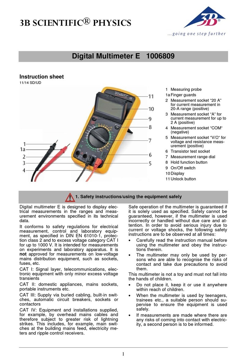
3B SCIENTIFIC PHYSICS E 1006809 User manual

3B SCIENTIFIC PHYSICS

3B SCIENTIFIC PHYSICS E 1006809 User manual

3B SCIENTIFIC PHYSICS 1017895 User manual

3B SCIENTIFIC PHYSICS

3B SCIENTIFIC PHYSICS 1017895 User manual

3B SCIENTIFIC PHYSICS E 1018832 User manual

3B SCIENTIFIC PHYSICS

3B SCIENTIFIC PHYSICS E 1018832 User manual

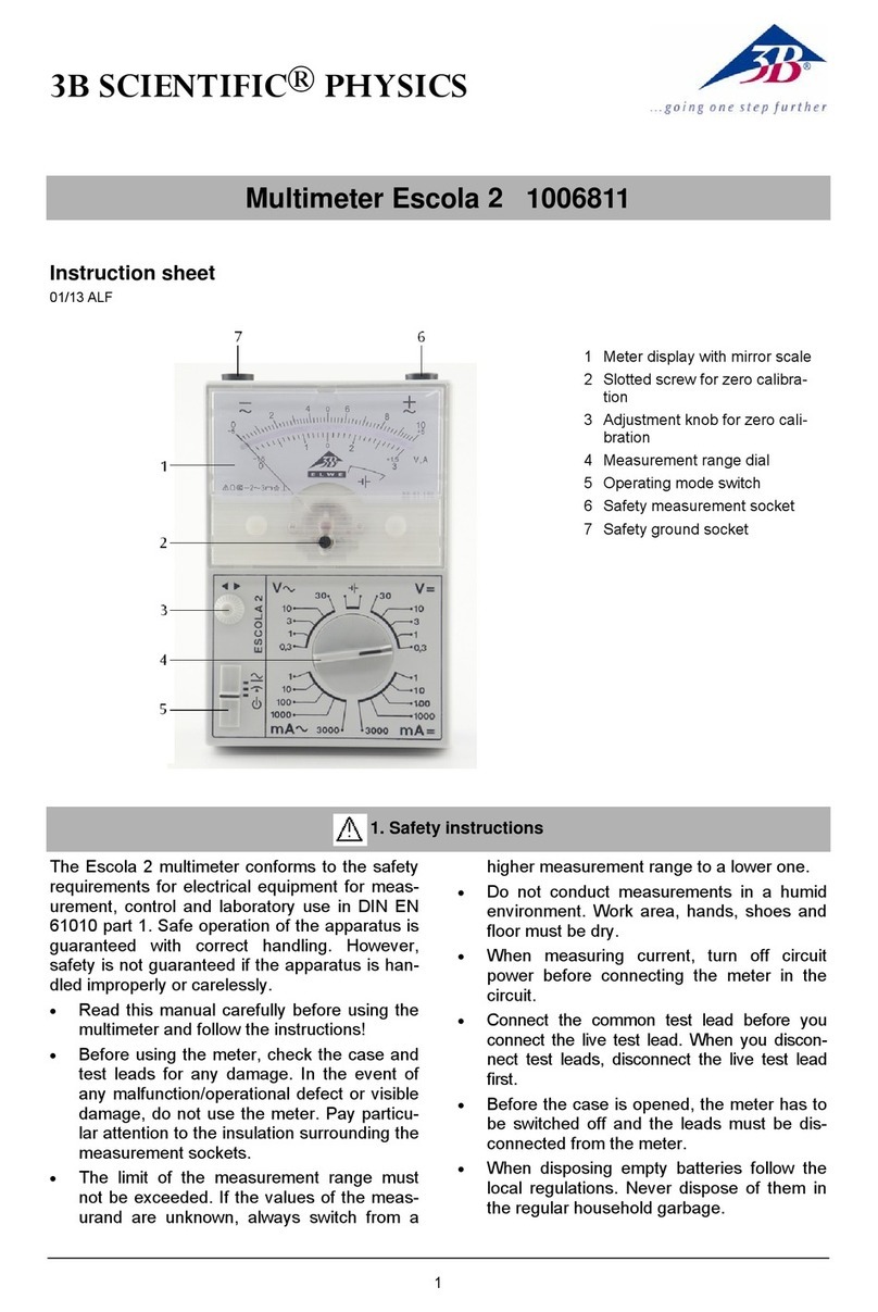
3B SCIENTIFIC PHYSICS Escola 2 1006811 User manual

3B SCIENTIFIC PHYSICS

3B SCIENTIFIC PHYSICS Escola 2 1006811 User manual

3B SCIENTIFIC PHYSICS Escola 10 User manual

3B SCIENTIFIC PHYSICS

3B SCIENTIFIC PHYSICS Escola 10 User manual

3B SCIENTIFIC PHYSICS Escola 30 User manual

3B SCIENTIFIC PHYSICS

3B SCIENTIFIC PHYSICS Escola 30 User manual

3B SCIENTIFIC PHYSICS Escola 10 1006810 User manual

3B SCIENTIFIC PHYSICS

3B SCIENTIFIC PHYSICS Escola 10 1006810 User manual

3B SCIENTIFIC PHYSICS Escola 10 User manual

3B SCIENTIFIC PHYSICS

3B SCIENTIFIC PHYSICS Escola 10 User manual

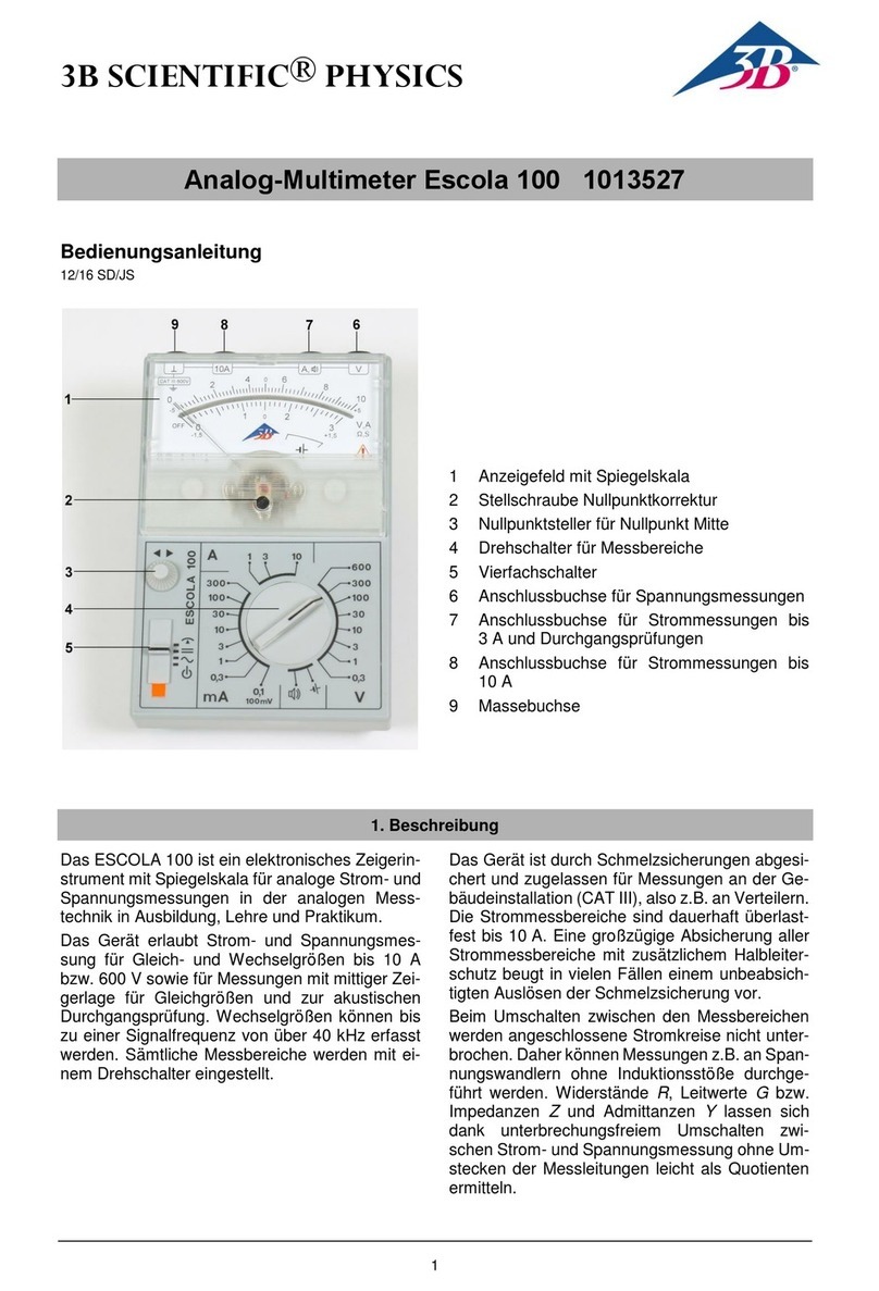
3B SCIENTIFIC PHYSICS 100 User manual

3B SCIENTIFIC PHYSICS

3B SCIENTIFIC PHYSICS 100 User manual

3B SCIENTIFIC PHYSICS Escola 2 User manual

3B SCIENTIFIC PHYSICS

3B SCIENTIFIC PHYSICS Escola 2 User manual

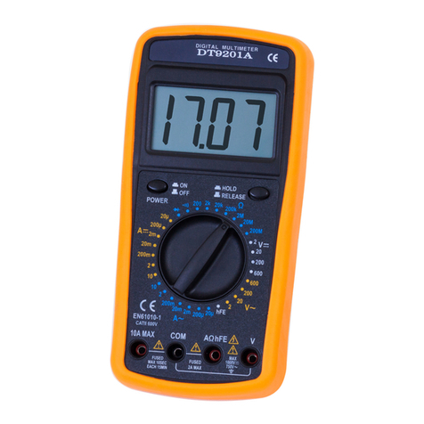
3B SCIENTIFIC PHYSICS DT9201A User manual

3B SCIENTIFIC PHYSICS

3B SCIENTIFIC PHYSICS DT9201A User manual

3B SCIENTIFIC PHYSICS E 1018832 User manual

3B SCIENTIFIC PHYSICS

3B SCIENTIFIC PHYSICS E 1018832 User manual

3B SCIENTIFIC PHYSICS 1018832 User manual
3B SCIENTIFIC PHYSICS

3B SCIENTIFIC PHYSICS 1018832 User manual

Popular Multimeter manuals by other brands

Projecta DT1000 quick start guide

Projecta

Projecta DT1000 quick start guide

PCE Instruments F09 user manual

PCE Instruments

PCE Instruments F09 user manual

SATA 03075 user manual

SATA

SATA 03075 user manual

Kusam-meco 306 user manual

Kusam-meco

Kusam-meco 306 user manual

Craftsman 82139 owner's manual

Craftsman

Craftsman 82139 owner's manual

histest DT830 Series Owner's operation manual

histest

histest DT830 Series Owner's operation manual

Tektronix KEITHLEY DAQ6510 Calibration manual

Tektronix

Tektronix KEITHLEY DAQ6510 Calibration manual

Extech Instruments 38390 user manual

Extech Instruments

Extech Instruments 38390 user manual

Extech Instruments 382100 user manual

Extech Instruments

Extech Instruments 382100 user manual

PCE Instruments PCE-AMM 5 user manual

PCE Instruments

PCE Instruments PCE-AMM 5 user manual

Amprobe 37XR-A user manual

Amprobe

Amprobe 37XR-A user manual

Signametrics SMX2040 Operator's manual

Signametrics

Signametrics SMX2040 Operator's manual

Fluke 8520A Operator's manual

Fluke

Fluke 8520A Operator's manual

RS PRO RS-338 instruction manual

RS PRO

RS PRO RS-338 instruction manual

KNOVA KN 8052 manual

KNOVA

KNOVA KN 8052 manual

LOVATO ELECTRIC DMG615 instruction manual

LOVATO ELECTRIC

LOVATO ELECTRIC DMG615 instruction manual

Amprobe 38XR-A user manual

Amprobe

Amprobe 38XR-A user manual

Fluke 187 user manual

Fluke

Fluke 187 user manual

manuals.online logo
manuals.online logoBrands
  • About & Mission
  • Contact us
  • Privacy Policy
  • Terms and Conditions

Copyright 2025 Manuals.Online. All Rights Reserved.